1997 SSANGYONG KORANDO warning
[x] Cancel search: warningPage 1593 of 2053
SSANGYONG MY2002
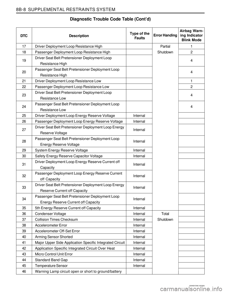
8B-8 SUPPLEMENTAL RESTRAINTS SYSTEM
Driver Deployment Loop Resistance High
Passenger Deployment Loop Resistance High
Driver Seat Belt Pretensioner Deployment Loop
Resistance High
Passenger Seat Belt Pretensioner Deployment Loop
Resistance High
Driver Deployment Loop Resistance Low
Passenger Deployment Loop Resistance Low
Driver Seat Belt Pretensioner Deployment Loop
Resistance Low
Passenger Seat Belt Pretensioner Deployment Loop
Resistance Low
Driver Deployment Loop Energy Reserve Voltage
Passenger Deployment Loop Energy Reserve Voltage
Driver Seat Belt Pretensioner Deployment Loop Energy
Reserve Voltage
Passenger Seat Belt Pretensioner Deployment Loop
Energy Reserve Voltage
System Energy Reserve Voltage
Safety Energy Reserve Capacitor Voltage
Driver Deployment Loop Energy Reserve Current off
Capacity
Passenger Deployment Loop Energy Reserve Current
off Capacity
Driver Seat Belt Pretensioner Deployment Loop Energy
Reserve Current off Capacity
Passenger Seat Belt Pretensioner Deployment Loop
Energy Reserve Current off Capacity
5th Energy Reserve Current off Capacity
Condenser Voltage
Collision Times Checksum
Accelerometer Error
Accelerometer Off-Set Error
Arming Sensor Shorted
Major Upper Side Application Specific Integrated Circuit
Application Specific Integrated Circuit Over Heat
Micro Control Unit Error
Standard Band Gap
Temperature Sensor
Warning Lamp circuit open or short to ground/battery 17
18
19
20
21
22
23
24
25
26
27
28
29
30
31
32
33
34
35
36
37
38
39
40
41
42
43
44
45
46
Diagnostic Trouble Code Table (Cont’d)
DTC DescriptionAirbag Warn-
ing Indicator
Blink Mode Error HandingType of the
Faults
Internal
Internal
Internal
Internal
Internal
Internal
Internal
Internal
Internal
Internal
Internal
Internal
Internal
Internal
Internal
Internal
Internal
Internal
Internal
Internal
Internal1
2
4
4
1
2
4
4
Partial
Shutdown
Total
Shutdown
Page 1596 of 2053
SUPPLEMENTAL RESTRAINTS SYSTEM 8B-11
SSANGYONG MY2002
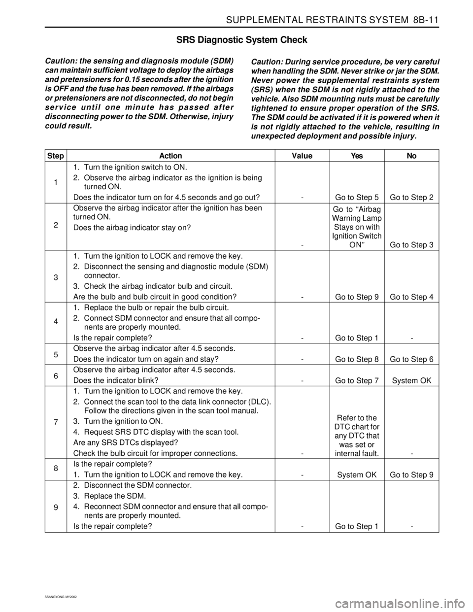
SRS Diagnostic System Check
Caution: the sensing and diagnosis module (SDM)
can maintain sufficient voltage to deploy the airbags
and pretensioners for 0.15 seconds after the ignition
is OFF and the fuse has been removed. If the airbags
or pretensioners are not disconnected, do not begin
service until one minute has passed after
disconnecting power to the SDM. Otherwise, injury
could result.Caution: During service procedure, be very careful
when handling the SDM. Never strike or jar the SDM.
Never power the supplemental restraints system
(SRS) when the SDM is not rigidly attached to the
vehicle. Also SDM mounting nuts must be carefully
tightened to ensure proper operation of the SRS.
The SDM could be activated if it is powered when it
is not rigidly attached to the vehicle, resulting in
unexpected deployment and possible injury.
Yes
Go to Step 5
Go to “Airbag
Warning Lamp
Stays on with
Ignition Switch
ON”
Go to Step 9
Go to Step 1
Go to Step 8
Go to Step 7
Refer to the
DTC chart for
any DTC that
was set or
internal fault.
System OK
Go to Step 1No
Go to Step 2
Go to Step 3
Go to Step 4
-
Go to Step 6
System OK
-
Go to Step 9
- Value
-
-
-
-
-
-
-
-
-
Step
1
2
3
4
5
6
7
8
9Action
1. Turn the ignition switch to ON.
2. Observe the airbag indicator as the ignition is being
turned ON.
Does the indicator turn on for 4.5 seconds and go out?
Observe the airbag indicator after the ignition has been
turned ON.
Does the airbag indicator stay on?
1. Turn the ignition to LOCK and remove the key.
2. Disconnect the sensing and diagnostic module (SDM)
connector.
3. Check the airbag indicator bulb and circuit.
Are the bulb and bulb circuit in good condition?
1. Replace the bulb or repair the bulb circuit.
2. Connect SDM connector and ensure that all compo-
nents are properly mounted.
Is the repair complete?
Observe the airbag indicator after 4.5 seconds.
Does the indicator turn on again and stay?
Observe the airbag indicator after 4.5 seconds.
Does the indicator blink?
1. Turn the ignition to LOCK and remove the key.
2. Connect the scan tool to the data link connector (DLC).
Follow the directions given in the scan tool manual.
3. Turn the ignition to ON.
4. Request SRS DTC display with the scan tool.
Are any SRS DTCs displayed?
Check the bulb circuit for improper connections.
Is the repair complete?
1. Turn the ignition to LOCK and remove the key.
2. Disconnect the SDM connector.
3. Replace the SDM.
4. Reconnect SDM connector and ensure that all compo-
nents are properly mounted.
Is the repair complete?
Page 1599 of 2053
SSANGYONG MY2002
8B-14 SUPPLEMENTAL RESTRAINTS SYSTEM
Yes
Go to Step 3
System OK
Go to “SDM
Integrity
Check”
Go to Step 6No
Go to Step 2
-
Go to Step 4
Go to Step 4 Value
-
-
9 v
9 - 16 vStep
1
2
3
4Action
Check the SDM connector to verify that it is properly
connected to the SDM.
Is the SDM connector properly connected?
Connect the SDM connector.
Is the repair complete?
1. Turn the ignition OFF.
2. Disconnect the SDM connector.
3. Turn the ignition ON.
4. Check the voltage at SDM connector terminal 5.
Is the ignition voltage greater than the specified value?
1. Turn the ignition ON.
2. Check the voltage supply to the airbag fuse F31.
Is the voltage within the specified value?
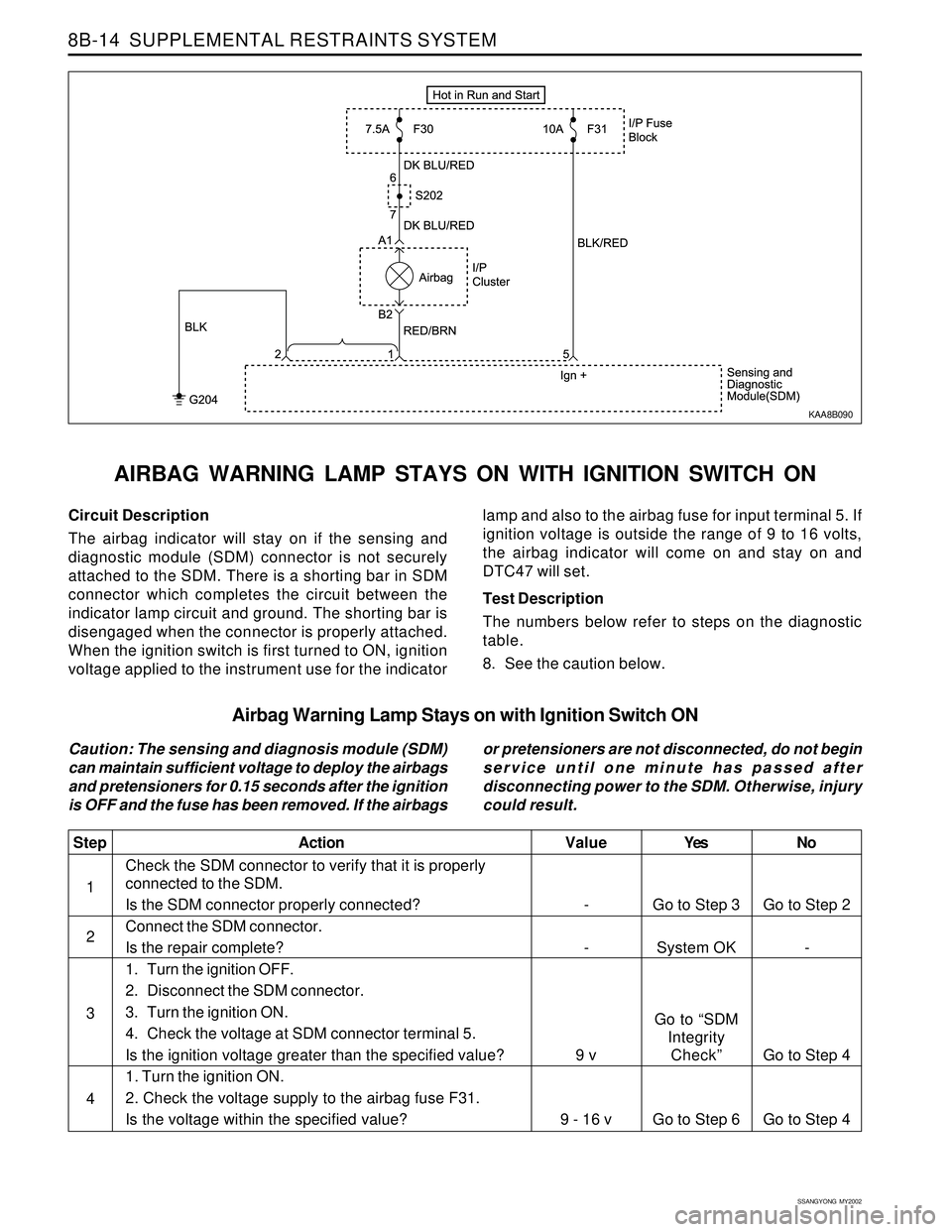
Circuit Description
The airbag indicator will stay on if the sensing and
diagnostic module (SDM) connector is not securely
attached to the SDM. There is a shorting bar in SDM
connector which completes the circuit between the
indicator lamp circuit and ground. The shorting bar is
disengaged when the connector is properly attached.
When the ignition switch is first turned to ON, ignition
voltage applied to the instrument use for the indicator
AIRBAG WARNING LAMP STAYS ON WITH IGNITION SWITCH ON
lamp and also to the airbag fuse for input terminal 5. If
ignition voltage is outside the range of 9 to 16 volts,
the airbag indicator will come on and stay on and
DTC47 will set.
Test Description
The numbers below refer to steps on the diagnostic
table.
8. See the caution below.
KAA8B090
Airbag Warning Lamp Stays on with Ignition Switch ON
Caution: The sensing and diagnosis module (SDM)
can maintain sufficient voltage to deploy the airbags
and pretensioners for 0.15 seconds after the ignition
is OFF and the fuse has been removed. If the airbagsor pretensioners are not disconnected, do not begin
service until one minute has passed after
disconnecting power to the SDM. Otherwise, injury
could result.
Page 1636 of 2053
SSANGYONG MY2002
8B-54 SUPPLEMENTAL RESTRAINTS SYSTEM
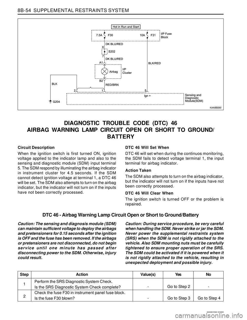
Circuit Description
When the ignition switch is first turned ON, ignition
voltage applied to the indicator lamp and also to the
sensing and diagnostic module (SDM) input terminal
5. The SDM respond by illuminating the airbag indicator
in instrument cluster for 4.5 seconds. If the SDM
cannot detect ignition voltage at terminal 1, a DTC 46
will be set. The SDM also attempts to turn on the airbag
indicator, but the indicator will not turn on if the inputs
have not been correctly processed.
DIAGNOSTIC TROUBLE CODE (DTC) 46
AIRBAG WARNING LAMP CIRCUIT OPEN OR SHORT TO GROUND/
BATTERY
DTC 46 Will Set When
DTC 46 will set when during the continuos monitoring,
the SDM fails to detect voltage terminal 1, the input
terminal for airbag indicator.
Action Taken
The SDM also attempts to turn on the airbag indicator,
but the indicator will not turn on if the inputs have not
been correctly processed.
DTC 46 Will Clear When
The ignition switch is turned OFF or the problem is
repaired.
KAA8B090
DTC 46 - Airbag Warning Lamp Circuit Open or Short to Ground/Battery
Caution: The sensing and diagnosis module (SDM)
can maintain sufficient voltage to deploy the airbags
and pretensioners for 0.15 seconds after the ignition
is OFF and the fuse has been removed. If the airbags
or pretensioners are not disconnected, do not begin
service until one minute has passed after
disconnecting power to the SDM. Otherwise, injury
could result.Caution: During service procedure, be very careful
when handling the SDM. Never strike or jar the SDM.
Never power the supplemental restraints system
(SRS) when the SDM is not rigidly attached to the
vehicle. Also SDM mounting nuts must be carefully
tightened to ensure proper operation of the SRS.
The SDM could be activated if it is powered when it
is not rigidly attached to the vehicle, resulting in
unexpected deployment and possible injury.
Perform the SRS Diagnostic System Check.
Is the SRS Diagnostic System Check complete?
Check the fuse F30 in instrument panel fuse block.
Is the fuse F30 blown?
StepAction Value(s) Yes No
1
- Go to Step 3 Go to Step 4 2
- Go to Step 2 -
Page 1649 of 2053
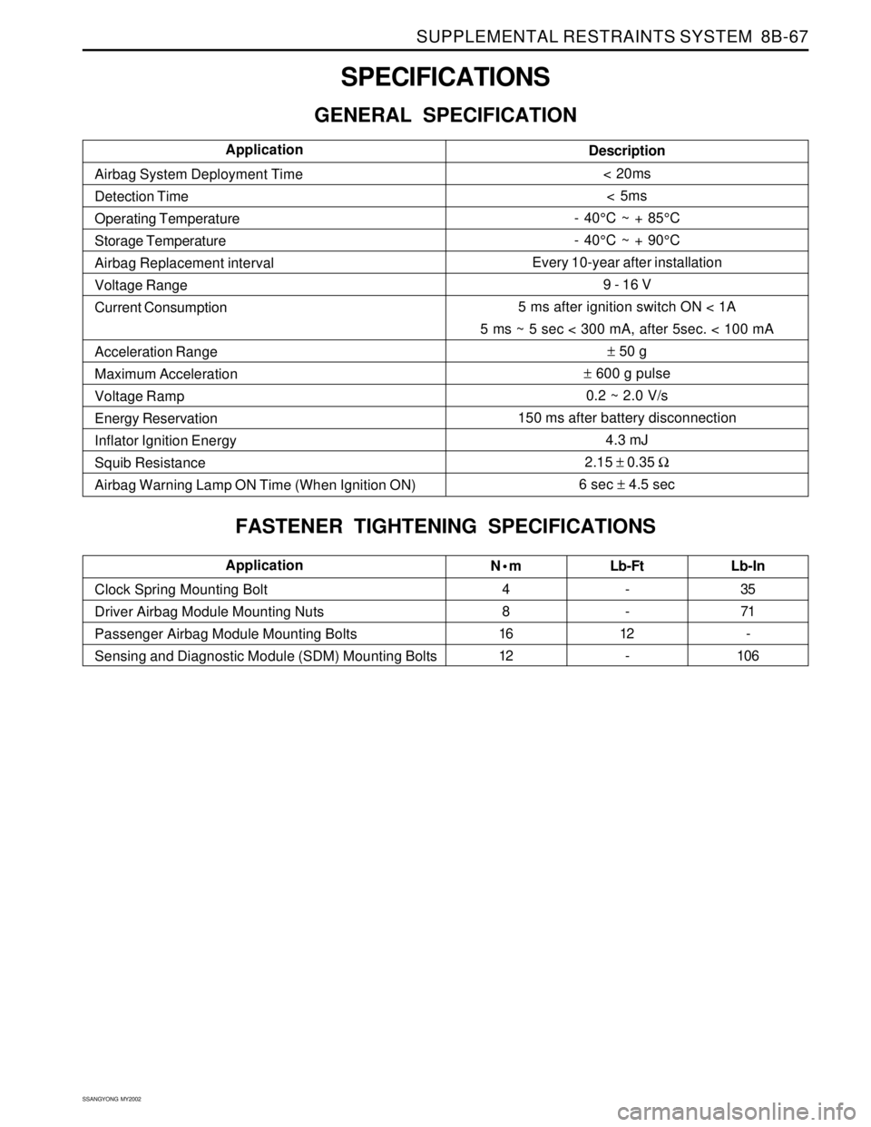
SUPPLEMENTAL RESTRAINTS SYSTEM 8B-67
SSANGYONG MY2002
SPECIFICATIONS
GENERAL SPECIFICATION
Nm
4
8
16
12Lb-Ft
-
-
12
- Clock Spring Mounting Bolt
Driver Airbag Module Mounting Nuts
Passenger Airbag Module Mounting Bolts
Sensing and Diagnostic Module (SDM) Mounting BoltsLb-In
35
71
-
106Application
Description
< 20ms
< 5ms
- 40°C ~ + 85°C
- 40°C ~ + 90°C
Every 10-year after installation
9 - 16 V
5 ms after ignition switch ON < 1A
5 ms ~ 5 sec < 300 mA, after 5sec. < 100 mA
± 50 g
± 600 g pulse
0.2 ~ 2.0 V/s
150 ms after battery disconnection
4.3 mJ
2.15 ± 0.35 Ω
6 sec ± 4.5 sec Airbag System Deployment Time
Detection Time
Operating Temperature
Storage Temperature
Airbag Replacement interval
Voltage Range
Current Consumption
Acceleration Range
Maximum Acceleration
Voltage Ramp
Energy Reservation
Inflator Ignition Energy
Squib Resistance
Airbag Warning Lamp ON Time (When Ignition ON)Application
FASTENER TIGHTENING SPECIFICATIONS
Page 1718 of 2053

SECTION 9E
INSTRUMENTATION, DRIVER INFORMATION
CAUTION: Disconnect the negative battery cable before removing or installing any electrical unit or when a
tool or equipment could easily come in contact with exposed electrical terminals. Disconnecting this cable
will help prevent personal injury and damage to the vehicle. The ignition must also be in LOCK unless
otherwise noted.
TABLE OF CONTENTS
Description and Operation.................................. 9E-2
Cigar Lighter....................................................... 9E-2
Ashtray.............................................................. 9E-2
Instrument Panel Vents....................................... 9E-2
Glove Box.......................................................... 9E-2
Digital Clock....................................................... 9E-2
Instrument Cluster.............................................. 9E-2
Speedometer and Tachometer............................ 9E-2
Trip Odometer.................................................... 9E-2
Fuel Gauge......................................................... 9E-2
Temperature Gauge............................................ 9E-2
Instrument Cluster Indicator Lamps..................... 9E-2
Chime Module.................................................... 9E-2
Components Locator ........................................... 9E-3
Instrumentation/Driver Information....................... 9E-3
Diagnostic Information and Procedure.............. 9E-5
Cigar Lighter....................................................... 9E-5
Disital Clock....................................................... 9E-5
Speedo Meter..................................................... 9E-6
Fuel Gauge......................................................... 9E-7
Temperature Gauge............................................ 9E-8
Instrument Cluster Indicator Lamps..................... 9E-9
Repair Instructions............................................. 9E-10
On-Vehice Service Unit Repair............................. 9E-10
Center Tray....................................................... 9E-10
Center Facia..................................................... 9E-10
Ashtray............................................................ 9E-10
Cigar Lighter..................................................... 9E-11Cup Holder....................................................... 9E-11
Instrument Panel Vent....................................... 9E-11
Glove Box........................................................ 9E-12
Chime Module.................................................. 9E-12
Hood Latch Release Handle.............................. 9E-12
Instrument Lower Cover.................................... 9E-13
Instrument Cluster Trim Panel........................... 9E-13
Instrument Cluster............................................ 9E-13
Speedometer/Odometer/Trip Odometer/
Tachometer................................................... 9E-14
Fuel Gauge....................................................... 9E-14
Temperature Gauge .......................................... 9E-15
Digital Clock..................................................... 9E-15
Instrument Cluster Indicator Lamps................... 9E-15
Instrument Panel............................................... 9E-16
Specifications.................................................... 9E-18
Bulb Usage Chart............................................. 9E-18
Schematic and Routing Diagram..................... 9E-19
Instrument Panel Illumination............................ 9E-19
Cluster (VSS, Meter & Gauge): Diesel.................9E-20
Cluster (VSS, Meter & Gauge): Gasoline............ 9E-21
Warning Lamp, TCS Indicator........................... 9E-22
Indicator........................................................... 9E-23
Warning Lamp.................................................. 9E-24
Digital Clock, Warning Cluster Illumination......... 9E-25
Selector Lever Position Lamp............................ 9E-26
Page 1726 of 2053
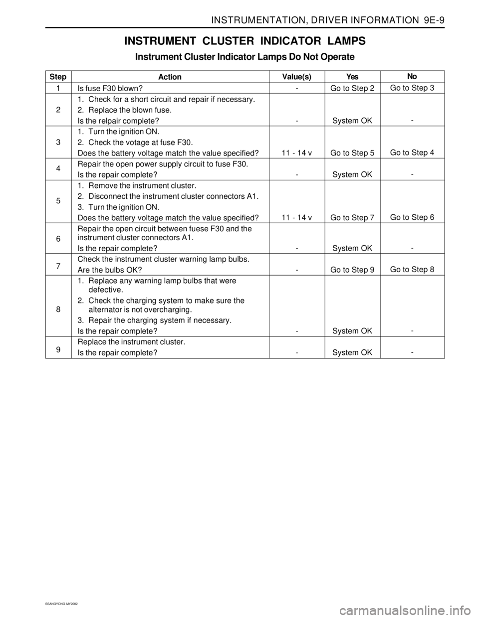
INSTRUMENTATION, DRIVER INFORMATION 9E-9
SSANGYONG MY2002
INSTRUMENT CLUSTER INDICATOR LAMPS
Instrument Cluster Indicator Lamps Do Not Operate
Step
1
2
3
4
5
6
7
8
9Action
Is fuse F30 blown?
1. Check for a short circuit and repair if necessary.
2. Replace the blown fuse.
Is the relpair complete?
1. Turn the ignition ON.
2. Check the votage at fuse F30.
Does the battery voltage match the value specified?
Repair the open power supply circuit to fuse F30.
Is the repair complete?
1. Remove the instrument cluster.
2. Disconnect the instrument cluster connectors A1.
3. Turn the ignition ON.
Does the battery voltage match the value specified?
Repair the open circuit between fuese F30 and the
instrument cluster connectors A1.
Is the repair complete?
Check the instrument cluster warning lamp bulbs.
Are the bulbs OK?
1. Replace any warning lamp bulbs that were
defective.
2. Check the charging system to make sure the
alternator is not overcharging.
3. Repair the charging system if necessary.
Is the repair complete?
Replace the instrument cluster.
Is the repair complete?Yes
Go to Step 2
System OK
Go to Step 5
System OK
Go to Step 7
System OK
Go to Step 9
System OK
System OKNo
Go to Step 3
-
Go to Step 4
-
Go to Step 6
-
Go to Step 8
-
- Value(s)
-
-
11 - 14 v
-
11 - 14 v
-
-
-
-
Page 1739 of 2053
SSANGYONG MY2002
9E-22 INSTRUMENTATION, DRIVER INFORMATION
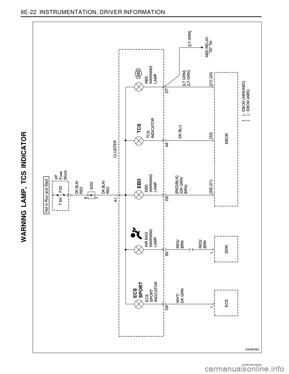
WARNING LAMP, TCS INDICATOR
KAA9E340