Page 1384 of 2053
SSANGYONG MY2002
5D1-14 TRANSFER CASE
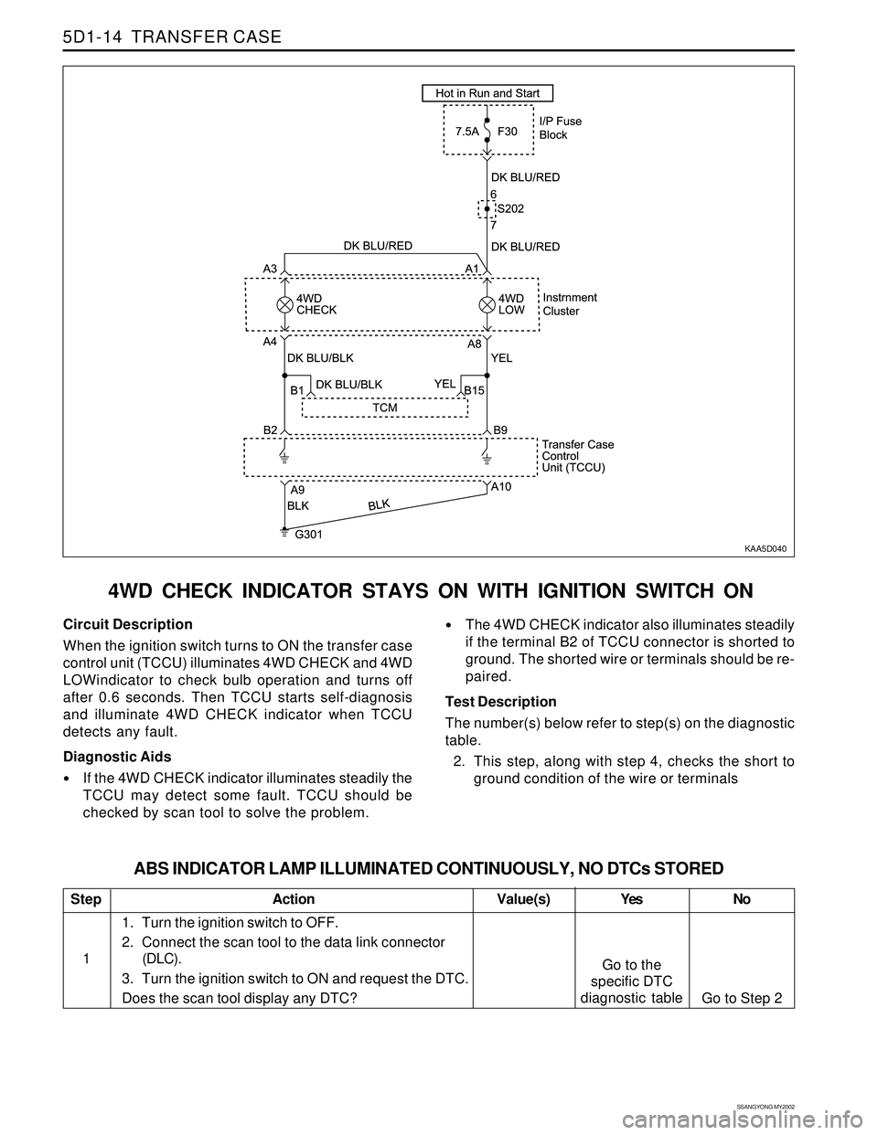
4WD CHECK INDICATOR STAYS ON WITH IGNITION SWITCH ON
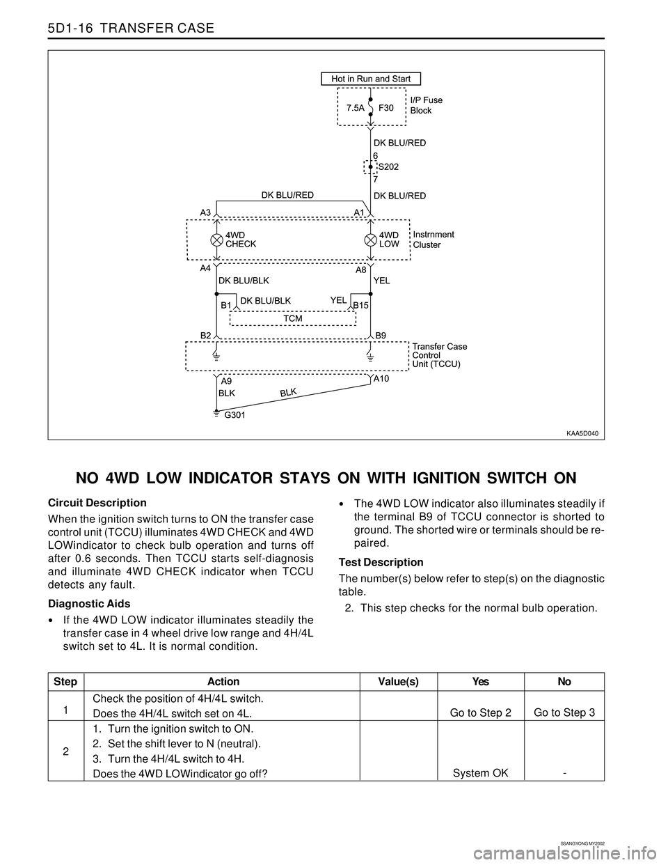
KAA5D040
Circuit Description
When the ignition switch turns to ON the transfer case
control unit (TCCU) illuminates 4WD CHECK and 4WD
LOWindicator to check bulb operation and turns off
after 0.6 seconds. Then TCCU starts self-diagnosis
and illuminate 4WD CHECK indicator when TCCU
detects any fault.
Diagnostic Aids
If the 4WD CHECK indicator illuminates steadily the
TCCU may detect some fault. TCCU should be
checked by scan tool to solve the problem.
The 4WD CHECK indicator also illuminates steadily
if the terminal B2 of TCCU connector is shorted to
ground. The shorted wire or terminals should be re-
paired.
Test Description
The number(s) below refer to step(s) on the diagnostic
table.
2. This step, along with step 4, checks the short to
ground condition of the wire or terminals
Step
1
ABS INDICATOR LAMP ILLUMINATED CONTINUOUSLY, NO DTCs STORED
Action Yes
Go to the
specific DTC
diagnostic tableNo
Go to Step 2 Value(s)
1. Turn the ignition switch to OFF.
2. Connect the scan tool to the data link connector
(DLC).
3. Turn the ignition switch to ON and request the DTC.
Does the scan tool display any DTC?
Page 1385 of 2053
TRANSFER CASE 5D1-15
SSANGYONG MY2002
Step
2
3
4
5Action
Yes
Go to Step 3
System OK
Go to Step 5
System OKNo
Go to Step 4
-
System OK
- Value(s)
1. Turn the ignition switch to OFF.
2. Disconnect the 18-pin connector from transfer case
control unit (TCCU).
3. Turn the ignition switch to ON and check the 4WD
CHECK bulb operation.
Does the 4WD CHECK indicator come on steadily?
Repair any short to ground circuit between terminal
B2 of TCCU connector and terminal A4 of cluster.
Is the repair complete?
1. Turn the ignition OFF.
2. Check the pin or terminals for damage or improper
connection.
3. Reconnect all the connectors.
4. Turn the ignition ON.
Does the 4WD CHECK indicator come on steadily?
Replace the TCCU.
Is the repair complete?
Page 1386 of 2053
SSANGYONG MY2002
5D1-16 TRANSFER CASE
KAA5D040
NO 4WD LOW INDICATOR STAYS ON WITH IGNITION SWITCH ON
Circuit Description
When the ignition switch turns to ON the transfer case
control unit (TCCU) illuminates 4WD CHECK and 4WD
LOWindicator to check bulb operation and turns off
after 0.6 seconds. Then TCCU starts self-diagnosis
and illuminate 4WD CHECK indicator when TCCU
detects any fault.
Diagnostic Aids
If the 4WD LOW indicator illuminates steadily the
transfer case in 4 wheel drive low range and 4H/4L
switch set to 4L. It is normal condition.
The 4WD LOW indicator also illuminates steadily if
the terminal B9 of TCCU connector is shorted to
ground. The shorted wire or terminals should be re-
paired.
Test Description
The number(s) below refer to step(s) on the diagnostic
table.
2. This step checks for the normal bulb operation.
Step
1
2
Action Yes
Go to Step 2
System OKNo
Go to Step 3
- Value(s)
Check the position of 4H/4L switch.
Does the 4H/4L switch set on 4L.
1. Turn the ignition switch to ON.
2. Set the shift lever to N (neutral).
3. Turn the 4H/4L switch to 4H.
Does the 4WD LOWindicator go off?
Page 1387 of 2053
TRANSFER CASE 5D1-17
SSANGYONG MY2002
Step
3
4
5
6
7ActionYes
Go to Step 4
System OK
Go to Step 6
System OK
System OKNo
Go to Step 5
-
System OK
Go to Step-7
- Value(s)
1. Turn the ignition switch to ON.
2. Set the shift lever to N (neutral).
3. Turn the 4H/4L switch to 4L.
Does the 4WD LOWindicator go off?
The wiring of 4H/4L switch is reversed. Repair the
wiring.
Is the repair complete?
1. Turn the ignition OFF.
2. Check the pin or terminals for damage or improper
connection.
3. Reconnect all the connectors.
4. Turn the ignition ON.
Does the 4WD LOW indicator come on steadily?
Repair any short to ground circuit between terminal B9
of TCCU connector and terminal A8 of cluster.
Is the repair complete?
Replace the TCCU.
Is the repair complete?
Page 1389 of 2053
TRANSFER CASE 5D1-67
SSANGYONG MY2002
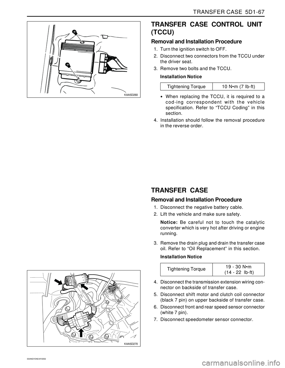
KAA5D260
KAA5D270
TRANSFER CASE CONTROL UNIT
(TCCU)
Removal and Installation Procedure
1. Turn the ignition switch to OFF.
2. Disconnect two connectors from the TCCU under
the driver seat.
3. Remove two bolts and the TCCU.
Installation Notice
Tightening Torque 10 Nm (7 lb-ft)
When replacing the TCCU, it is required to a
cod-ing correspondent with the vehicle
specification. Refer to “TCCU Coding” in this
section.
4. Installation should follow the removal procedure
in the reverse order.
TRANSFER CASE
Removal and Installation Procedure
1. Disconnect the negative battery cable.
2. Lift the vehicle and make sure safety.
Notice: Be careful not to touch the catalytic
converter which is very hot after driving or engine
running.
3. Remove the drain plug and drain the transfer case
oil. Refer to “Oil Replacement” in this section.
Installation Notice
4. Disconnect the transmission extension wiring con-
nector on backside of transfer case.
5. Disconnect shift motor and clutch coil connector
(black 7 pin) on upper backside of transfer case.
6. Disconnect front and rear speed sensor connector
(white 7 pin).
7. Disconnect speedometer sensor connector.
Tightening Torque19 - 30 Nm
(14 - 22 lb-ft)
Page 1401 of 2053
SECTION 5D2
TRANSFER CASE (PART TIME - 4408)
TABLE OF CONTENTS
General Infromation and Operation..................5D2-2
4WD Operation Overview...................................5D2-2
System Structure...............................................5D2-3
2H Mode (Rear Wheel Drive)..............................5D2-5
4H Mode (4WD Drive - High Speed)...................5D2-6
4H Mode (4WD Drive - Low Speed)....................5D2-7
System Description...........................................5D2-8
Specifications....................................................5D2-9
Diagnostic Infromation and Procedures..........5D2-10
General Diagnosis...........................................5D2-10
Self-Diagnosis Test..........................................5D2-11
Diagnostic Diagram .........................................5D2-15
Component Locator .........................................5D2-16
Cross Sectional View.......................................5D2-16Transfer Case Assembly..................................5D2-17
Disassembly and Assembly............................5D2-18
Maintenance and Repair.................................5D2-20
On-Vehicle Service.............................................5D2-20
Maintenance of Transfer Case Lubricant...........5D2-20
4H and 4L Indicator .........................................5D2-21
TCCU Inspection.............................................5D2-21
Transfer Case Assembly..................................5D2-22
TCCU..............................................................5D2-24
Unit Repair........................................................5D2-25
Disassembly Procedure...................................5D2-25
Assembly Procedure.......................................5D2-35
Page 1404 of 2053
SSANGYONG MY2002
5D2-4 TRANSFER CASE (PART TIME - 4408)
Power Flow
TCCU
Switch Transfer
2H, 4H
↔ 4L
Rear Propeller Shaft
Rear Wheel
Front Axle
Transfer
Locking Hub Solenoid
Locking Hub
OperationVacuum System Operation
Front Propeller Shaft
Front Wheel
Rear Axle
Page 1406 of 2053
SSANGYONG MY2002
5D2-6 TRANSFER CASE (PART TIME - 4408)
� y
������ ������
yyyyyy yyyyyy
� y
�� ��
yy yy
������ ������
������
������
yyyyyy yyyyyy
yyyyyy
yyyyyy
���� ����
����
yyyy yyyy
yyyy
��� ���
���
���
���
yyy yyy
yyy
yyy
yyy
����� �����
�����
yyyyy yyyyy
yyyyy
� y������ ������ ������
yyyyyy yyyyyy yyyyyy
�� ��
yy yy
���� yyyy�� ��
yy yy�� ��
yy yy� �
y y� ��
� y�� yy�� yy
��� ���
yyy yyy� y�� ��
yy yy�� yy�� yy�� yy� y���� ����
yyyy yyyy� y� y
� y
�� ��
yy yy
�� yy
� �
y y
� �
y y
�� yy
�� ��
yy yy
���� yyyy
���������� ����������
����������
yyyyyyyyyy yyyyyyyyyy
yyyyyyyyyy�� yy�� yy
� �
y y�� �� �
y y
� �
y y
��� yyy
� y
�� ��
yy yy
�� yy
�� yy� �
y y
���� ����
yyyy yyyy
� �
y y� �
y y� y�� yy
�� yy� �
y y�� ��
yy yy
� y
�� ��
yy yy
��� ��� ���
yyy yyy yyy
�
� �
y y
�� ��
yy yy
��� ��� ��� ���
yyy yyy yyy yyy�� ��
yy yy
������ yyyyyy
� y� y
�� yy�� yy
�� ��
yy yy�� yy
�� yy
������ ������
������
������
������
yyyyyy yyyyyy
yyyyyy
yyyyyy
yyyyyy
�� ��
yy yy
�� ��
yy yy
� �
y y� �
y y
� y
�� ��
yy yy� y� y
�� ��
��
yy yy
yy
�� yy
� �
y y� �
y y
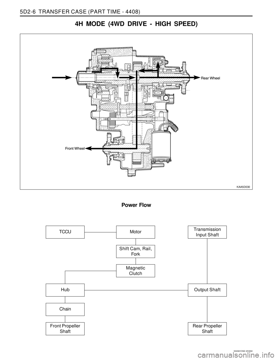
4H MODE (4WD DRIVE - HIGH SPEED)
KAA5D030
Power Flow
Hub
Chain
Motor
Output Shaft
Front Propeller
Shaft
Transmission
Input Shaft
Rear Propeller
Shaft
Shift Cam, Rail,
Fork
Magnetic
Clutch
TCCU