1997 SSANGYONG KORANDO Throttle body
[x] Cancel search: Throttle bodyPage 426 of 2053

1F2 -- 4 M161 ENGINE CONTROLS
D AEW OO M Y_2000
FASTENER TIGHTENING SPECIFICATIONS
ApplicationNSmLb-FtLb-In
Camshaft Position Sensor Retaining Bolts10--89
Canister Mounting Bolts6--53
Coolant Temperature Sensor3022--
Crankshaft Position Sensor Retaining Bolt10--89
Engine Control Module (ECM) Mounting Bracket Nuts10--89
Fuel Filter Mounting Bracket Bolt6--53
Fuel Filter Lines2821--
Fuel Pressure Test Connector2518--
Fuel Rail Assembly Bolts2518--
Fuel Return And Supply Lines2317--
Fuel Tank Retaining Nuts3828--
Knock Sensor Mounting Bolt2518--
Oxygen Sensor5541--
Pedal Position Censor Mounting Bolts And Nut6--53
Throttle Body Bolts12--106
Page 486 of 2053

1F2 -- 68 M161 ENGINE CONTROLS
D AEW OO M Y_2000
ACCELERATOR PEDAL MODULE
YAA1F620
The Acceleration Pedal Position (APP) sensor is mounted on the accelerator pedal assembly. The sensor is actually
two individual APP sensors and one housing. This sensor works with the Throttle Position (TP) sensor to provide input
to the Engine Control Module (ECM) regarding driver requested accelerator pedal and throttle angle at the throttle
body.
When the APP sensor is defected:
When the APP 1 or APP 2 sensor is defected condition, the engine is still running at idle condition but, the accelerator
pedal reaction is not response correctly and also, the engine rpmwill be reacted to 4,000 rpm slowly. If the APP 1
sensor is out of order, the APP 2 sensor will be conducted with signal as a default signal but, the throttle valve opening
is limited 60% and delayed opening speed.
When the TP sensor or servo motor is defected:
When the TP 1, 2 sensor or servo motor is defected condition, the throttle valvewill be closed to the spring capsule by
spring force, at this condition, the throttle valvewillopen 10°~20°and engine rpmwill be controlled by ECM will
opening (On/Off) time of injector. Theengine rpmwill be maintaining 900 rpm (at idle) to 1,800 according to theengine
load.
Page 519 of 2053

M161 ENGINE CONTROLS 1F2 -- 101
D AEW OO M Y_2000
YAA1F740
THROTTLE BODY (INTEGRATED
WITH THE ACTUATOR)
Removal and Installation Procedure
1. Disconnect the negative battery cable.
2. Disconnect the mass air flow sensor connector.
3. Disconnect the mass air flow sensor from the air fil-
ter housing.
4. Remove the intake air duct mounting bolts.
Installation Notice
Tightening Torque
9NSm (80 lb-in)
5. Remove the air inlet housing clamps.
6. Remove the inlet air housing.
YAA1F790
7. Disconnect the throttle body electrical connector.
8. Remove the throttle body bolts.
Installation Notice
Tightening Torque
12 NSm (106 lb-in)
9. Remove the vacuum hose.
KAA1D240
10. Remove the throttle body and discard the gasket.
Important:Use care in cleaning old gasket material.
Sharp tools may damage sealing surfaces.
11. Installation should follow the removal procedure in
the reverse order.
Page 522 of 2053

1F2 -- 104 M161 ENGINE CONTROLS
D AEW OO M Y_2000
KAB1F400
PURGE CONTROL VALVE
Removal and Installation Procedure
1. Disconnect the negative battery cable.
2. Disconnect the purge control valve connector.
3. Disconnect the throttle body-to-purge control valve
hose from the purge control valve.
4. Disconnect the canister-to-purge control valve hose
from the purge control valve.
5. Remove the purge control valve.
6. Installation should follow the removal provedure in
the reverse order.
KAB1F410
CANISTER
Removal and Installation Procedure
Caution: Canister and vacuum hoses contain fuel
vapors. Do not smoke in the area or permit an open
flame.
1. Disconnect the fuel tank-to-canister hose form the
canister.
2. Disconnect the canister-to-purge control valve hose
form the canister.
KAB1F400
3. Remove the canister mounting bolts.
Installation Notice
Tightening Torque
6NSm (53 lb-in)
4. Remove the canister.
5. Installation should follow the removal procedure in
the reverse order.
YAA1F810
CAMSHAFT POSITION SENSOR
Removal and Installation Procedure
1. Disconnect the negative battery cable.
2. Disconnect the electrical connector from the cam-
shaft position sensor.
3. Remove the camshaft position sensor retaining bolt.
Installation Notice
Tightening Torque
10 NSm (89 Ib-in)
Page 1097 of 2053

AUTOMATIC TRANSMISSION 5A-3
SSANGYONG MY2002
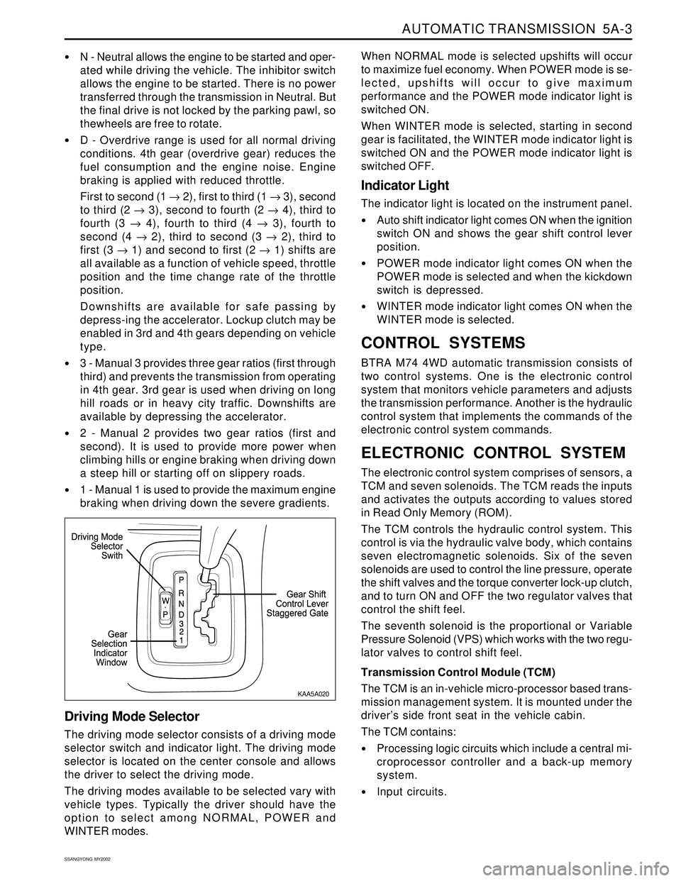
N - Neutral allows the engine to be started and oper-
ated while driving the vehicle. The inhibitor switch
allows the engine to be started. There is no power
transferred through the transmission in Neutral. But
the final drive is not locked by the parking pawl, so
thewheels are free to rotate.
D - Overdrive range is used for all normal driving
conditions. 4th gear (overdrive gear) reduces the
fuel consumption and the engine noise. Engine
braking is applied with reduced throttle.
First to second (1 → 2), first to third (1 → 3), second
to third (2 → 3), second to fourth (2 → 4), third to
fourth (3 → 4), fourth to third (4 → 3), fourth to
second (4 → 2), third to second (3 → 2), third to
first (3 → 1) and second to first (2 → 1) shifts are
all available as a function of vehicle speed, throttle
position and the time change rate of the throttle
position.
Downshifts are available for safe passing by
depress-ing the accelerator. Lockup clutch may be
enabled in 3rd and 4th gears depending on vehicle
type.
3 - Manual 3 provides three gear ratios (first through
third) and prevents the transmission from operating
in 4th gear. 3rd gear is used when driving on long
hill roads or in heavy city traffic. Downshifts are
available by depressing the accelerator.
2 - Manual 2 provides two gear ratios (first and
second). It is used to provide more power when
climbing hills or engine braking when driving down
a steep hill or starting off on slippery roads.
1 - Manual 1 is used to provide the maximum engine
braking when driving down the severe gradients.When NORMAL mode is selected upshifts will occur
to maximize fuel economy. When POWER mode is se-
lected, upshifts will occur to give maximum
performance and the POWER mode indicator light is
switched ON.
When WINTER mode is selected, starting in second
gear is facilitated, the WINTER mode indicator light is
switched ON and the POWER mode indicator light is
switched OFF.
Indicator Light
The indicator light is located on the instrument panel.
Auto shift indicator light comes ON when the ignition
switch ON and shows the gear shift control lever
position.
POWER mode indicator light comes ON when the
POWER mode is selected and when the kickdown
switch is depressed.
WINTER mode indicator light comes ON when the
WINTER mode is selected.
CONTROL SYSTEMS
BTRA M74 4WD automatic transmission consists of
two control systems. One is the electronic control
system that monitors vehicle parameters and adjusts
the transmission performance. Another is the hydraulic
control system that implements the commands of the
electronic control system commands.
ELECTRONIC CONTROL SYSTEM
The electronic control system comprises of sensors, a
TCM and seven solenoids. The TCM reads the inputs
and activates the outputs according to values stored
in Read Only Memory (ROM).
The TCM controls the hydraulic control system. This
control is via the hydraulic valve body, which contains
seven electromagnetic solenoids. Six of the seven
solenoids are used to control the line pressure, operate
the shift valves and the torque converter lock-up clutch,
and to turn ON and OFF the two regulator valves that
control the shift feel.
The seventh solenoid is the proportional or Variable
Pressure Solenoid (VPS) which works with the two regu-
lator valves to control shift feel.
Transmission Control Module (TCM)
The TCM is an in-vehicle micro-processor based trans-
mission management system. It is mounted under the
driver’s side front seat in the vehicle cabin.
The TCM contains:
Processing logic circuits which include a central mi-
croprocessor controller and a back-up memory
system.
Input circuits.
Driving Mode Selector
The driving mode selector consists of a driving mode
selector switch and indicator light. The driving mode
selector is located on the center console and allows
the driver to select the driving mode.
The driving modes available to be selected vary with
vehicle types. Typically the driver should have the
option to select among NORMAL, POWER and
WINTER modes.
KAA5A020
Page 1107 of 2053

AUTOMATIC TRANSMISSION 5A-13
SSANGYONG MY2002
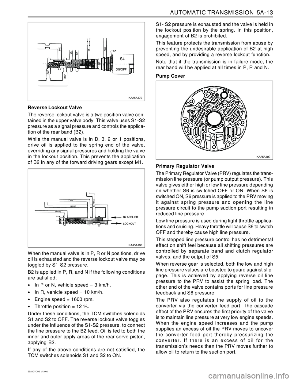
Reverse Lockout Valve
The reverse lockout valve is a two position valve con-
tained in the upper valve body. This valve uses S1-S2
pressure as a signal pressure and controls the applica-
tion of the rear band (B2).
While the manual valve is in D, 3, 2 or 1 positions,
drive oil is applied to the spring end of the valve,
overriding any signal pressures and holding the valve
in the lockout position. This prevents the application
of B2 in any of the forward driving gears except M1.S1- S2 pressure is exhausted and the valve is held in
the lockout position by the spring. In this position,
engagement of B2 is prohibited.
This feature protects the transmission from abuse by
preventing the undesirable application of B2 at high
speed, and by providing a reverse lockout function.
Note that if the transmission is in failure mode, the
rear band will be applied at all times in P, R and N.
Pump Cover
When the manual valve is in P, R or N positions, drive
oil is exhausted and the reverse lockout valve may be
toggled by S1-S2 pressure.
B2 is applied in P, R, and N if the following conditions
are satisfied;
In P or N, vehicle speed = 3 km/h.
In R, vehicle speed = 10 km/h.
Engine speed = 1600 rpm.
Throttle position = 12 %.
Under these conditions, the TCM switches solenoids
S1 and S2 to OFF. The reverse lockout valve toggles
under the influence of the S1-S2 pressure, to connect
the line pressure to the B2 feed. Oil is fed to both the
inner and outer apply areas of the rear servo piston,
applying B2.
If any of the above conditions are not satisfied, the
TCM switches solenoids S1 and S2 to ON.Primary Regulator Valve
The Primary Regulator Valve (PRV) regulates the trans-
mission line pressure (or pump output pressure). This
valve gives either high or low line pressure depending
on whether S6 is switched OFF or ON. When S6 is
switched ON, S6 pressure is applied to the PRV moving
it against spring pressure and opening the line
pressure circuit to the pump suction port resulting in
reduced line pressure.
Low line pressure is used during light throttle applica-
tions and cruising. Heavy throttle will cause S6 to switch
OFF and thereby cause high line pressure.
This stepped line pressure control has no detrimental
effect on shift feel because all shifting pressures are
controlled by separate band and clutch regulator
valves, and the output of S5.
When reverse gear is selected, both the low and high
line pressure values are boosted to guard against slip-
page. This is achieved by applying reverse oil line
pressure to the PRV to assist the spring load. The
other end of the valve contains ports for line pressure
feedback and S6 pressure.
The PRV also regulates the supply of oil to the
converter via the converter feed port. The cascade
effect of the PRV ensures the first priority of the valve
is to maintain line pressure at very low engine speeds.
When the engine speed increases and the pump
supplies an excess of oil the PRV moves to uncover
the converter feed port thereby pressurizing the
converter. If there is an excess of oil for the
transmission’s needs then the PRV moves further to
allow oil to return to the suction port.
KAA5A170
KAA5A180KAA5A190
Page 1255 of 2053

5A-160 AUTOMATIC TRANSMISSION
SSANGYONG MY2002
UNIT REPAIR
REBUILD WARNINGS
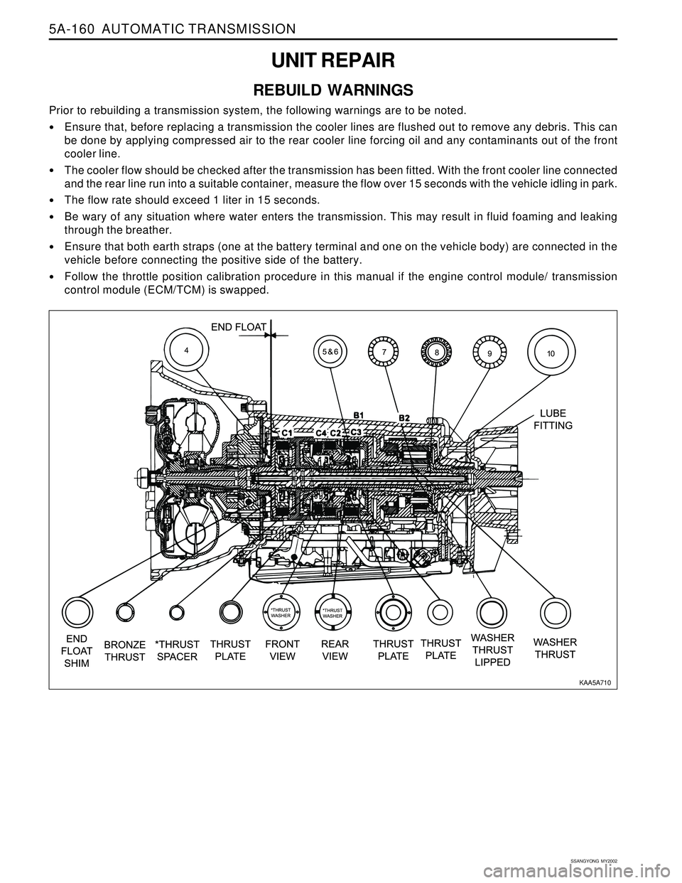
Prior to rebuilding a transmission system, the following warnings are to be noted.
Ensure that, before replacing a transmission the cooler lines are flushed out to remove any debris. This can
be done by applying compressed air to the rear cooler line forcing oil and any contaminants out of the front
cooler line.
The cooler flow should be checked after the transmission has been fitted. With the front cooler line connected
and the rear line run into a suitable container, measure the flow over 15 seconds with the vehicle idling in park.
The flow rate should exceed 1 liter in 15 seconds.
Be wary of any situation where water enters the transmission. This may result in fluid foaming and leaking
through the breather.
Ensure that both earth straps (one at the battery terminal and one on the vehicle body) are connected in the
vehicle before connecting the positive side of the battery.
Follow the throttle position calibration procedure in this manual if the engine control module/ transmission
control module (ECM/TCM) is swapped.
KAA5A710
Page 1671 of 2053

SSANGYONG MY2002
9A-20 BODY WIRING SYSTEM
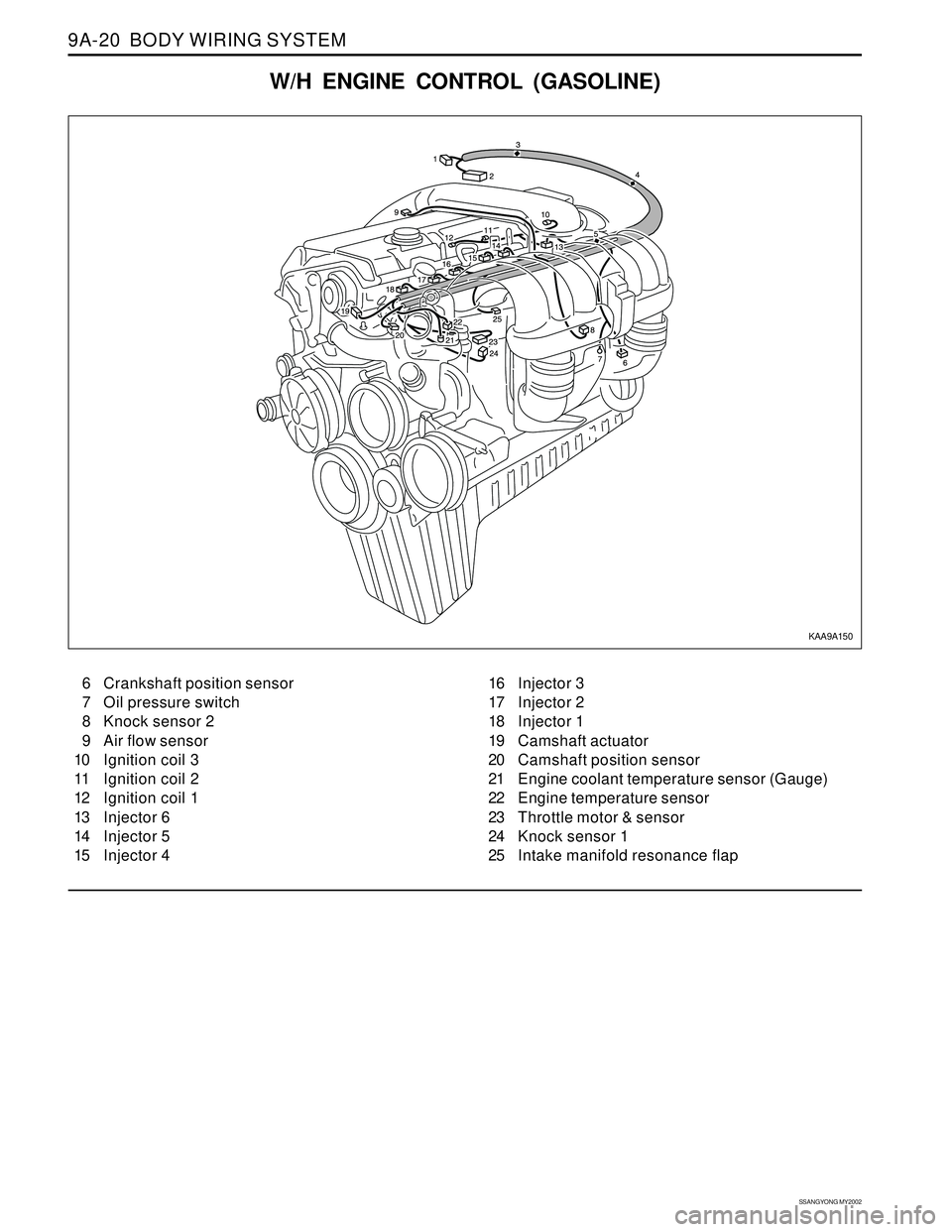
W/H ENGINE CONTROL (GASOLINE)
6 Crankshaft position sensor
7 Oil pressure switch
8 Knock sensor 2
9 Air flow sensor
10 Ignition coil 3
11 Ignition coil 2
12 Ignition coil 1
13 Injector 6
14 Injector 5
15 Injector 416 Injector 3
17 Injector 2
18 Injector 1
19 Camshaft actuator
20 Camshaft position sensor
21 Engine coolant temperature sensor (Gauge)
22 Engine temperature sensor
23 Throttle motor & sensor
24 Knock sensor 1
25 Intake manifold resonance flap
KAA9A150