Page 185 of 208
COOLING
Water pump
CLEANING
It is very important not to scratch the gasket faces
of all aluminium components.
Use the product Décapjoint to dissolve the part
of the gasket which remains attached.
Apply the product to the part to be cleaned, wait
approximately 10 minutes, then remove it using a
wooden spatula.
The wearing of gloves is recommended during
this operation.
REFITTING
Refitting is the reverse of removal.
Refit and tension the accessories belt. (see section
07 "Accessories belt tension").
Fill and bleed the cooling circuit (see section 19
"Filling and bleeding").
19F8Q Engine
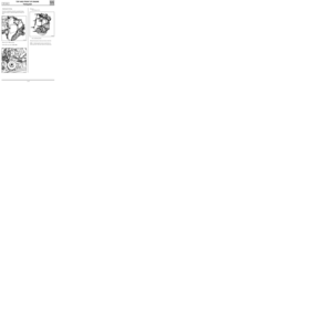
- the bolts mounting the water pump and extract
this from above.
13089S
19-11
Page 186 of 208

EXHAUST
General
19
ATTACHMENT OF THE PIPE UNDER THE BODY
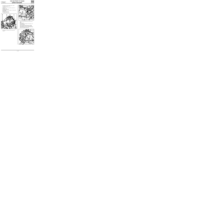
The attachment of the pipe under the body is by
the rubber mounting at (1).
This can generally be unhooked by hand by ta-
king the weight off the exhaust pipe.
However, in certain cases, it may be necessary to
slacken the bolts retaining the support ( 2) under
the body in order to more easily unhook the rub-
ber mountings. During operation, the catalytic converter reaches
high temperatures, and consequently, it is vital
not to park the vehicle in a place where combusti-
ble materials could come into contact with it, and,
as a result, ignite.
Under certain conditions, these materials could
ignite.
IMPORTANT:
- the seal, between the exhaust manifold gas-
ket face and the catalytic converter (inclu-
sive), must be in perfect condition,
_ it is imperative that every gasket removed be
REPLACED (especially at the catalytic converter
flange)
- during removal and refitting, the catalytic
converter must not undergo repeated mecha-
nical shocks, as it will be damaged.
CUTTING THE EXHAUST PIPE
The exhaust pipes are of the monoblock type.
There is no join from the beginning of the cataly-
tic converter or the expansion box, to the end of
the silencer.
It will therefore be necessary, when replacing one
of the components in After Sales, to cut the
exhaust pipe.
For this, it is absolutely essential to accurately :
- mark the area to be cut,
- use the cutting tool Mot. 1199-01,
- fit the after sales sleeve .
12847-1R
19-12
Page 187 of 208
EXHAUST
General
19
MARKING THE AREA TO BE CUT
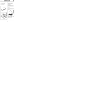
The area to be cut is defined by two punch marks
on the exhaust pipe.
99226-1R
Depending on engine, there are a maximum of
two cutting areas on the exhaust pipe, situated
between the catalytic converter and the
expansion box and between the expansion box
and the silencer.
The distance between the two markings is 90 mm.
To cut the tube, mark the central point (D) bet-
ween the two markings (P
1 and P2).
DI1901
90 mm
P
1P
2 D
IMPORTANT: to cut the exhaust pipe, it is essen-
tial to use tool Mot. 1199-01; this tool allows
2mm thick pipes to be cut.
19-13
Page 188 of 208

EXHAUST
General
19
FITTING THE AFTER SALES SLEEVE
95478R1
Once a collar has been used once, renew it.
The nut on the collar has a groove (A) to ensure it
is tightened to the correct torque. When the nut is
tightened and the groove disappears, it causes a
distinct clicking sound and the nut is then tighte-
ned to the correct torque (2.5 daN.m).
NOTE : there are two different diameters of
sleeve available:
-∅ 50 mm,
-∅ 45 mm .
IMPORTANT:
- check that there is no point of contact bet-
ween the exhaust pipe and the vehicle body,
- check for the presence and correct positioning
of all heat shields for the exhaust pipe,
- check that the two cutting marks are correctly
aligned.
99227S
To avoid any leaks in the exhaust pipe, the sleeve
must be correctly positioned over the two exhaust
pipe sections. The pipe must be against the stops
inside the sleeve.
Begin by positioning the sleeve over the used sec-
tion of the pipe, adjust the collar by tightening
gently.
Check the position of the pipe in relation to the
stops.
Fit the new section of the pipe.
Before fitting the sleeve on the pipe, apply a little
mastic to the inner ring on the sleeve to prevent
leaks.
(Exhaust mastic, Part Number. 77 01 421 161
SODICAM).
IMPORTANT : the bolt and nut used for tighte-
ning the sleeve must be aligned vertically to
avoid any risks of touching the underside of the
body.
19-14
Page 189 of 208
EXHAUST
Pipe assembly
19
DIAGRAM OF EXHAUST PIPES AND LOCATION OF CUTTING AREAS
1 Expansion box
2 Silencer
3 Catalytic converter
ZC Pipe cutting area
13124R
E7J Engine D7F Engine
13126R
19-15
Page 190 of 208
EXHAUST
Pipe assembly
19
DIAGRAM OF EXHAUST PIPES AND LOCATION OF CUTTING AREAS
13125R
1 Catalytic converter
2 Silencer
ZC Pipe cutting area F8Q Engine
19-16
Page 191 of 208
Mot. 1199-01 Exhaust pipe cutting tool
Mot. 1265
Mot. 1265-01
FUEL TANK
Fuel tank
19
IMPORTANT : during all the fuel tank removal
and refitting operations, refrain from smoking
and be sure not to handle incandescent objects in
the vicinity of the working area.
DRAINING THE FUEL TANK (Petrol version)
Remove the pump-sender unit assembly steel ac-
cess cover.
Remove the clip which shows if the assembly has
been pushed in (if fitted).
Disconnect the quick release union at (1), tool
Mot. 1265.
EQUIPMENT REQUIRED
INTAIRCO pneumatic siphoning pump, for
petrol or diesel tank draining system (see EQUIPMENT
catalogue).
SPECIAL TOOLING REQUIRED
97163R2
Attach to the outlet at (A), a pipe long enough to
be placed into a container outside the vehicle .
NOTE : Alternatively, an INTAIRCO pneumatic si-
phoning pump may be used (see
EQUIPMENT ca-
talogue). Sender unit- pump nut 7
TIGHTENING TORQUES (in daN.m)
Pliers for removing quick release
fuel unions
19-17
Page 192 of 208
FUEL TANK
Fuel tank
19
In the engine compartment, disconnect the fuel
pump relay at (K) , which is located in the engine
connection unit.
12839S
DRAINING THE FUEL TANK ( Diesel version)
Since Diesel versions are not fitted with an electri-
cal fuel pump, a manual pump must be used to
drain the tank.
For example, the
INTAIRCO pneumatic siphoning
pump is suitable for this operation (see
EQUIPMENT catalogue),
Shunt tracks 3 and 5 and let the fuel flow until it
runs out in intermittent jets.
Disconnect the shunt.
Reconnect the relay.
Disconnect the battery.Remove the pump-sender unit steel access cover.
Remove the clip which shows if the assembly has
been pushed in (if fitted).
Disconnect the quick release union at (1), tool
Mot. 1265.
99641S
97163R2
Connect the pneumatic pump rubber tube to the
outlet union at (A).
Drain the tank.
19-18