Page 9 of 208
ENGINE AND ENGINE PERIPHERALS
Engine - Gearbox
Left-hand side of the vehicle
Remove:
- the brake caliper mounting bolt, then fix it to
the shock absorber spring,
- the three driveshaft gaiter mounting bolts,
- the track rod end with the aid of tool
T.Av.476,
- the shock absorber base bolts.
Tilt the hub to disconnect the driveshaft from the
gearbox.
Right-hand side of the vehicle
Remove:
- the driveshaft roll pins with the punches
B.Vi.31-01,
- the brake caliper mounting bolt, then fix it to
the shock absorber spring,
- the track rod end with the aid of tool
T.Av.476,
- the shock absorber base bolts.
Tilt the hub to disconnect the driveshaft from the
gearbox.
Remove the earth strap mounting bolt (gearbox
side)
10D7F engine
10-5
Page 10 of 208
ENGINE AND ENGINE PERIPHERALS
Engine - Gearbox
- the heater hoses on the bulkhead side (with
plastic unions),
10
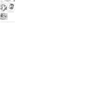
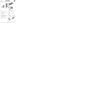
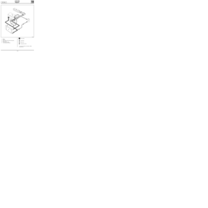
Disconnect the gear control at the position of the
gearbox output lever after releasing the gaiter.
93912R1
Slacken bolt (A) without removing it and remove
bolt (B) from the engine tie-bar.
92661R1
Disconnect:
- the accelerator cable,
- the canister pipe,
- the brake servo vacuum pipe,
- the hoses between the radiator and the
engine block, on the engine block side,
13085R
(with metal unions),
13084R
- the connectors of the oxygen sensor and fan,
- the fuel pipes. D7F engine
10-6
Page 11 of 208
ENGINE AND ENGINE PERIPHERALS
Engine - Gearbox
- the mounting bolts (2) of the rubber engine
mounting pad (1).
Note the position of the engine mounting pad(1)
in relation to the body.
10
99893S
12924R1
Remove:
- the gearbox side support,Remove the engine and transmission assembly
after taking the power assisted steering unit out
of the engine compartment and protecting the
radiator. Remove:
- the computer support plate.
- the power assisted steering pipe mountings
on the engine,
- the power assisted steering pump belt (see
section 07),
- the power assisted steering pulley,
- the power assisted steering bolts.
Release the power assisted steering unit.
Attach the load positioner to the engine lifting
rings.
12924R2
D7F engine
10-7
Page 12 of 208
ENGINE AND ENGINE PERIPHERALS
Engine - Gearbox
10
12924R3
Apply Rhodorseal 5661 to the driveshaft roll pin hole.
Press the brake pedal several times to bring the pistons into contact with the brake pads.
Refit the power assisted steering pump belt (see section 07).
Fill:
- the gearbox with oil,
- the engine with oil (if necessary),
- the cooling circuit and bleed it (see section 19).
REFITTING (special notes)
Refitting is the reverse of removal.
Tighten the suspended engine mounting bolts to the recommended torque.
NOTE : tighten the suspended engine mounting bolts on the body in the order recommended below:
-1⇒bolt A to a torque of 2.1 daNm.
-2⇒bolt B to a torque of 2.1 daNm.
-3⇒bolt C to a torque of 2.1 daNm. D7F engine
10-8
Page 13 of 208

ENGINE AND ENGINE PERIPHERALS
Engine and transmission assembly
10
REMOVAL
Put the vehicle on a 2 post lift.
Disconnect:
- the battery,
- the electrical connectors from the engine
connection unit and its environment.
13034S
Drain:
- the cooling circuit (disconnect the bottom
hose of the radiator),
- the gearbox oil if necessary,
- the engine oil if necessary.
Remove:
- the battery,
- the wheels,
- the air intake pipe,
- the upper radiator mountings,
- the expansion bottle and fix it to the engine,
- the power assisted steering fluid reservoir,
and secure it onto the engine. Shock absorber base bolts 18
Track rod end 3.7
Front sub-frame mounting bolt 6.2
Rear sub-frame mounting bolt 10.5
Driveshaft gaiter mounting bolt 2.5
Wheel bolt 9
Mounting nut for rubber engine mounting
pad on left suspended engine mounting 6.2
Mounting bolt for front right suspended
engine mounting on the engine 6.2
Mounting bolt for front right suspended
engine mounting on the body 6.2
Steering shaft yoke bolt 2.5
TIGHTENING TORQUES (in daN.m)
D7F engine
SPECIAL TOOLING REQUIRED
B. Vi. 31-01 Set of punches for roll pins
Mot. 1040-01 Dummy sub-frame for
removing and refitting engine
and transmission assembly
Mot. 1202 Hose clip pliers
Mot. 1311-06 Tool for removal of fuel pipe
Mot. 1379 Tool for retaining engine on
sub-frame
T. Av. 476 Ball joint extractor
T. Av. 1233-01 Tool for sub-frame and axle
assembly
10-9
Page 14 of 208

ENGINE AND ENGINE PERIPHERALS
Engine and transmission assembly
Disconnect:
- the accelerator cable,
- the canister pipe,
- the brake servo pipe,
- the heater hoses,
- the oxygen sensor connector,
- the fuel pipes.
Remove:
- the shock absorber base bolts,
- the steering shaft yoke bolt.
10
97390-1R
SPECIAL NOTES FOR VEHICLES FITTED WITH
DRIVER’S AIR BAG
WARNING
In order to avoid any risk of damage to the rotary
switch beneath the steering wheel, the following
instructions should be followed:
• Before disconnecting the steering column from
the rack, the steering wheel MUST be immobi-
lised with the wheels straight with the aid of a
"steering wheel lock" throughout the opera-
tion.
• If there is any doubt about the rotary switch
being properly centred, the steering wheel
must be removed in order to apply the centring
method described in the Technical Note cove-
ring the 2nd generation air bag.
REMINDER: this kind of work must only be carried
out by properly trained and qualified staff.
Remove:
- both the sub-frame reinforcements,
- the earth strap mounting bolt on the body
side,
- the exhaust downpipe nuts. D7F engine
10-10
Page 15 of 208
ENGINE AND ENGINE PERIPHERALS
Engine and transmission assembly
Insert a wooden block between the gearbox and
the sub-frame.
Diagram showing the holes drilled in tool Mot.
1040-01 (dimensions in mm).
10
Disconnect the gear control:
- at the position of the gearbox output lever af-
ter releasing the gaiter,
- at the level of the gear lever after removing
the central heat shield.
Pull the control lever (2) towards the rear of the
vehicle.
10621R
Fit tool Mot. 1379 onto the sub-frame and take
the weight off the right-hand engine mounting,
using the threaded rod (1).
10267R1
93912R2
Fix tool Mot. 1040-01 underneath the sub-frame,
having first fitted the shims Mot. 1379 onto this
tool.
92442-1R2
D7F engine
10-11
Page 16 of 208
ENGINE AND ENGINE PERIPHERALS
Engine and transmission assembly
10
Remove:
- the gearbox suspended mounting nut, then
tap it with a copper hammer to release the
suspended mounting stud,
- the suspended engine mounting bolts on the
engine.
Lower the lift until the tool touches the ground.
Remove the four mounting bolts of the sub-
frame.
Take out the engine and transmission assembly by
lifting the body.
98755R
D7F engine
10-12