Page 145 of 208
STARTING-CHARGING
Alternator
16
REMOVAL
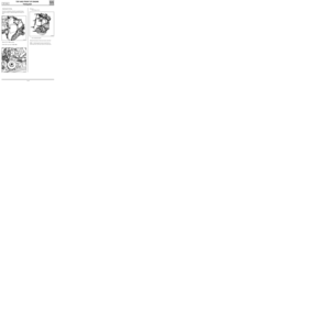
Place the vehicle on a two post lift.
Disconnect the battery as well as all electrical
connections leading the alternator.
Remove :
- the front right wheel arch,
- the alternator mountings as well as the belt,
- the support (A),
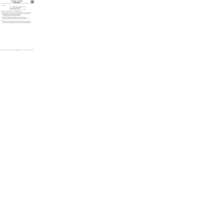
SPECIAL TOOLING REQUIRED
Mot. 1273 Tool for checking belt tension
13092R
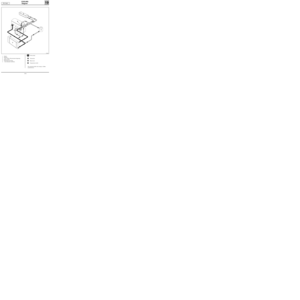
- the cross member mounting bolts and remove
it in order to remove the alternator.
13188S
REFITTING
Refitting is the reverse of removal.
See section 07 "Accessories belt tension" for the
tension values. F8Q Engine
16-6
Page 146 of 208
STARTING - CHARGING
Starter motor
16
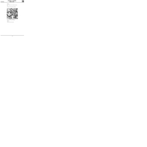
ENGINE STARTER MOTOR
D7FVALEO D7 E1
Bosch 0001116001
E7J
D6 RA 73
F8Q Bosch 0001108180
IDENTIFICATION
16-7
Page 147 of 208

STARTING - CHARGING
Starter motor
16
OPTIMA 5800 Diagnostic station
CHECKING THE STARTER MOTOR USING THE DIAGNOSTIC STATION
Checking of the starter motor is carried out using the OPTIMA 5800, by measuring the battery voltage and
the current absorbed in the engine starting phase. The following operation faults may be highlighted :
- a fault in the battery ( the voltage falls during the starting phase),
- locking of the starter motor (the current absorbed is too high),
- a fault in the engine starter gear (the current absorbed is too low).
In order to carry out the measurement, it is necessary to stop the vehicle from starting :
- for D7F and E7J engines : disconnect the engine speed sensor (located on the clutch housing ,
- for
F8Q engines : disconnect the pump electrical solenoid and isolate the terminal.
NOTE :
- an open circuit on the engine speed sensor or the ignition creates a fault memorised by the injection
computer, this fault must then be erased from the memory using the
XR25 (see "Injection" section),
- if the engine is fitted with an immobiliser, it is sufficient to lock the doors using the remote control.
FAULT FINDING
SPECIAL TOOLING REQUIRED
16-8
Page 148 of 208
STARTING - CHARGING
Starter motor
16
REMOVAL
Place the vehicle on a lift, and disconnect the bat-
tery.
Disconnect the starter electrical connections.
10076R
Remove the two starter mounting bolts.
REMOVAL
Refitting is the reverse of removal. D7F Engine
16-9
Page 149 of 208
STARTING - CHARGING
Starter motor
16
REMOVAL
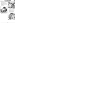
Place the vehicle on a two post lift.
Remove :
- the battery,
- the injection computer mounting, after ha-
ving disconnected the 55 track connector as
well as the impact switch connector,
13088S
- the mounting (1) for the power assisted stee-
ring pipe, along with the strut at (A),
13336-1R
- the front right hand wheel ,
- the driveshaft pin using punches B. Vi. 31-01,
- the upper shock absorber bolt and slacken the
lower bolt.
Tilt the hub and release the driveshaft assembly
from the gearbox.
Remove the starter connections , as well as the
mounting bolts and extract these from the bot-
tom of the vehicle.
REFITTING
Refitting is the reverse of removal.
Check for the presence of the centring dowel
which should be located at (B).
13087R
E7J Engine
16-10
Page 150 of 208
STARTING - CHARGING
Starter motor
16
REMOVAL
Place the vehicle on a two post lift.
Remove:
- the air filter inlet pipe,
- the battery,
- the computer support mounting bolts as well
as the connectors at (1), then move the
computer support/ diesel filter assembly to
one side.
13088R3
- the starter mounting bolts and the heat shield
(A),- the starter connections,
- the starter motor itself.
REFITTING
Refitting is the reverse of removal.
Check for the presence of the centring dowel,
which should be located at (B).
13087R1
F8Q Engine
16-11
Page 151 of 208

IGNITION
Semi-static ignition
17
PRESENTATION
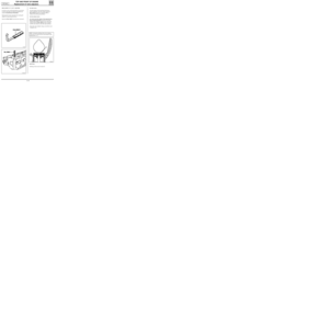
The system comprises:
- the injection computer (the ignition power
stage is integrated into the computer),
- two dual output coils, (for the
D7F engine,
these are moulded into one),
- four spark plugs,
- an anti-interference condenser (4).
DESCRIPTION - OPERATING PRINCIPLE
COMPUTER
The injection computer (120), depending on the
information received from various sensors, but
principally depending on the engine speed and
load, determines:
- the number of degrees of advance to be used
and consequently the ignition point,
- which cylinders are at TDC and consequently
the ignition coil to be operated.
The spark is created at the two cylinders at TDC by
cutting the earth to the coil concerned.
COILS (1)
There are two coils. They are of the dual output
type (they cannot be separated in the
D7F en-
gine ).
They are controlled separately by the computer.
They create two sparks simultaneously.
Both coils are connected to an anti-interference
condenser.
99931-1R2
D7F Engine
E7J Engine
13242R
Special features of the E7J engine
The coil at (2) has a black electrical connector. It
creates a spark simultaneously at cylinders 1 and
4. It is controlled by track 28 of the injection
computer.
The coil at (3) has a grey electrical connector . It
creates a spark simultaneously at cylinders 2 and
3. It is controlled by track 29 of the injection
computer.
17-1
Page 152 of 208
IGNITION
Semi-static ignition
17
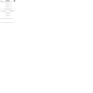
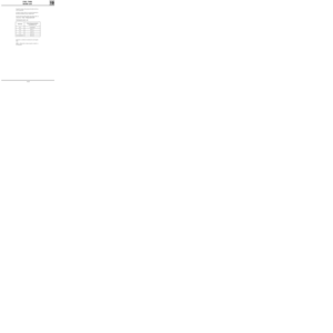
Test to be made
between tracksResistance
1 - 2 1.5 Ω
1 - 3 1 Ω
1 - 4 1 Ω
2 - 3 1 Ω
2 - 4 1 Ω
3 - 4 0.6 Ω
HT - HT8 kΩ
D7F Engine
Electrical connector
Track Allocation
1coil control for cylinders
1-4
2coil control for cylinders
3-2
3 +after ignition
4+anti-interference
condenser
Test to be made
between tracksResistance
1 - 2 0.5 Ω
1 - 3 1 Ω
2 - 3 1 Ω
HT - HT10 kΩ
Track Allocation
1+anti-interference
condenser
2 +after ignition
3coil control by
computer
D7F Engine
Electrical connector
17-2