Page 17 of 105
FRONT AXLE
Brake pads
31
REMOVAL
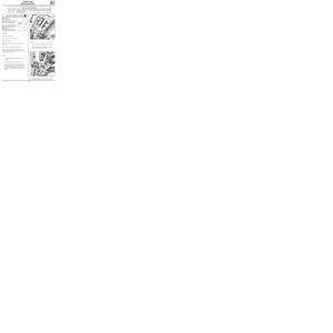
Disconnect the wear warning light wire (if fitted).
Push the piston back, sliding the caliper by hand.
Remove the lower brake caliper guide bolt.
SPECIAL TOOLING REQUIRED
Fre. 823 Tool for pushing piston back
Wheel bolts 9
Brake caliper guide bolt 4
12994R
REFITTING
Push back the caliper piston using tool Fre. 823.
Fit new brake pads.
The brake pad with the wear warning light wire
(if fitted) is fitted to the inside.
Refit the caliper into position and fit the lower
guide bolt.
Tighten the guide bolt to the recommended
torque 4 daN.m.
Reconnect the wear warning light wire (if fitted).
Press the brake pedal several times to bring the
piston into contact with the pads.
TIGHTENING TORQUES (in daN.m)
Pivot the caliper around the upper bolt.
Remove the brake pads.
Check:
- the condition and mounting of the piston dust
cover,
- the condition of the guide dust cover.
31-4
Page 18 of 105

FRONT AXLE
Front brake calipers
31
REPAIR
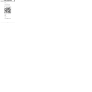
NOTE :
if there are any scratches in the caliper
bore, the complete caliper must be replaced.
To do this:
- remove the brake caliper,
- remove the rubber dust cover,
- remove the piston using compressed air,
inserting a wooden block between the caliper
and the piston to prevent damage to the
piston: any trace of damage to the piston skirt
will render it unusable
- remove the seal from the caliper groove using
a flexible rounded edge blade (eg feeler
gauge).
Clean the parts using methylated spirits.
Replace any faulty parts using original parts and
then refit the seal, piston and dust seal.
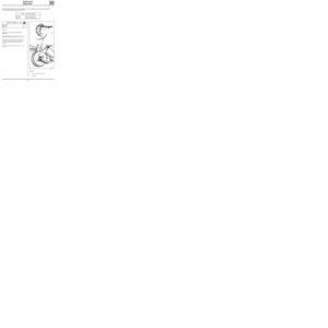
REMOVAL
In the passenger compartment, fit a pedal press
(limits the amount of brake fluid which will run
out).
Release the brake pipe at the wheel cylinder end.
Remove the brake pads (see previous page).
Remove the two mounting bolts for the caliper on
the stub axle carrier.
Completely release the brake pipe by turning the
caliper.
Check the condition of the pipe and replace it if
necessary.
REFITTING
Fit the pipe onto the caliper.
Remove the pedal press.
To check the correct operation of the caliper
cylinder, slacken the bleed screw and wait for
brake fluid to run out.
Retighten the bleed screw.
Refit the caliper on the stub axle carrier and
tighten the bolts to the recommended torque.
Refit the pads and the wheel cylinder (follow the
method described previously).
Wheel bolts 9
Brake caliper guide bolt 4
Brake caliper mounting bolt 10
TIGHTENING TORQUES (in daN.m)
31-5
Page 19 of 105
FRONT AXLE
Brake discs
31
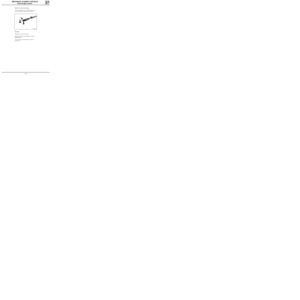
Brake discs cannot be reground. If they are too
heavily worn or are scratched they must be repla-
ced.
Wheel bolts 9
Brake caliper mounting bolt 10
REMOVAL
Remove:
- the two brake assembly mounting bolts
(attach the assembly to the spring),
- the two mounting bolts securing the disc to
the hub,
- the disc.
REFITTING
Refitting is the reverse of removal.
NOTE : when a brake disc is replaced, the pads
must also be renewed.
TIGHTENING TORQUES (in daN.m)
31-6
Page 20 of 105

FRONT AXLE
Stub axle carrier bearing
31
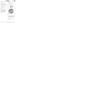
SPECIAL TOOLING REQUIRED
Rou. 15 -01 Shaft protector
Rou. 604 -01 Hub locking tool
T.Av.476 Ball joint extractor
T.Av. 1050-02 Tool for pushing driveshaft back
Driveshaft nut 28
Wheel bolts 9
Shock absorber base nut 18
Brake caliper mounting bolt 10
Track rod end nut 3.7
Key nut on stub axle carrier 5.5
83348G
REMOVAL
Disconnect the battery.
Remove:
- the wheel,
- the brake caliper and attach it to the spring so
the pipe is not damaged,
- the track rod end using tool
T.Av. 476,
- the driveshaft nut.
Push back the driveshaft using tool :
T. Av. 1050-02.
Remove:
- the brake disc,
- the lower ball joint nut and key,
- the two shock absorber base bolts,
- the hub / stub axle carrier / bearing assembly.
TIGHTENING TORQUES (in daN.m)Remove the hub on the press.
Remove the lower bush from the hub using an ex-
tractor with jaws and tool Rou. 15-01.
Remove the locking spring ring from the stub axle
carrier.
On the press remove the remainder of the bea-
ring, taking care to take the weight on the inner
bush using a tube of the same diameter.
31-7
Page 21 of 105
FRONT AXLE
Stub axle carrier bearing
31
79057S
REFITTING
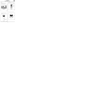
Fit the bearing on the press, into the stub axle car-
rier using a tube of external diameter
70 mm and bore 66 mm, taking the weight on the
external bush.
IMPORTANT: do not take the weight on the inter-
nal bush to avoid damaging the bearing as the
force required to push the bearing on is quite
considerable.
79058-1S
Fit a new locking spring ring.
Coat each sealing lip of the bearing with multi-
purpose grease.
Fit on the press, using a tube of external diameter
48 mm and internal diameter 42 mm, taking the
weight on the inner bearing bush.
85902S1
Refit the hub / stub axle carrier / bearing assembly
to the vehicle.
Refitting is then the reverse of removal. Observe the
correct tightening torques.
31-8
Page 22 of 105

Spring compressor
FRONT AXLE
Spring and shock absorber assembly
31
Shock absorber base mounting bolt 18
Rebound stop nut 6
Wheel bolts 9
REMOVAL
Put the vehicle on a four post lift.
Remove:
- the wheels,
- the shock absorber base mounting bolts.
NOTE : release the ABS sensor wiring if this is
fitted on the base of the shock absorber.
Remove the upper shock absorber nut in the
engine compartment.
Remove the shock absorber and spring assembly.
TIGHTENING TORQUES (in daN.m)
EQUIPMENT REQUIRED
Replacing a shock absorber
When replacing a shock absorber, fit it in a vice
and compress the spring using the spring
compressor tool.
Remove the spring retaining nut.
Remove the spring and the intermediate parts.
If necessary, replace the shock absorber pad and
the rotating stop.
When refitting, ensure all components are
replaced in the correct location and then
decompress the spring.
NOTE : apply grease between the ends of the
spring and its stops.
REFITTING
Refitting is then the reverse of removal. Observe
the correct tightening torques.
31-9
Page 23 of 105
FRONT AXLE
Anti-roll bar
REFITTING
Refit:
- the rubber mounting nuts using tool
Sus. 1414,
31
REMOVAL
Put the vehicle on a four post lift.
Remove:
- the two lower bolts from the exhaust
downpipe,
- the two sub-frame reinforcements (4 bolts),
12993-1R
Central bearing bolt 3
Rubber mounting nut 1.5
TIGHTENING TORQUES (in daN.m)
SPECIAL TOOLING REQUIRED
Sus. 1413 Central bearing compressor
Sus. 1414 Rubber mounting compressor
- the two rubber mounting nuts at the ends of
the anti-roll bar,
- the two bolts from the central bearings on the
bar.
Check the condition of the bearings and the
rubber mountings and replace them if necessary.
12992R
31-10
Page 24 of 105
FRONT AXLE
Anti-roll bar
31
- the central bearing bolts using tool
Sus. 1413.
12991R
- the two sub-frame reinforcements,
- the lower bolts on the exhaust downpipe.
Rubber bush locking position :
UNLADEN.
31-11