1997 RENAULT KANGOO Chassis Workshop Manual
-
 1
1 -
 2
2 -
 3
3 -
 4
4 -
 5
5 -
 6
6 -
 7
7 -
 8
8 -
 9
9 -
 10
10 -
 11
11 -
 12
12 -
 13
13 -
 14
14 -
 15
15 -
 16
16 -
 17
17 -
 18
18 -
 19
19 -
 20
20 -
 21
21 -
 22
22 -
 23
23 -
 24
24 -
 25
25 -
 26
26 -
 27
27 -
 28
28 -
 29
29 -
 30
30 -
 31
31 -
 32
32 -
 33
33 -
 34
34 -
 35
35 -
 36
36 -
 37
37 -
 38
38 -
 39
39 -
 40
40 -
 41
41 -
 42
42 -
 43
43 -
 44
44 -
 45
45 -
 46
46 -
 47
47 -
 48
48 -
 49
49 -
 50
50 -
 51
51 -
 52
52 -
 53
53 -
 54
54 -
 55
55 -
 56
56 -
 57
57 -
 58
58 -
 59
59 -
 60
60 -
 61
61 -
 62
62 -
 63
63 -
 64
64 -
 65
65 -
 66
66 -
 67
67 -
 68
68 -
 69
69 -
 70
70 -
 71
71 -
 72
72 -
 73
73 -
 74
74 -
 75
75 -
 76
76 -
 77
77 -
 78
78 -
 79
79 -
 80
80 -
 81
81 -
 82
82 -
 83
83 -
 84
84 -
 85
85 -
 86
86 -
 87
87 -
 88
88 -
 89
89 -
 90
90 -
 91
91 -
 92
92 -
 93
93 -
 94
94 -
 95
95 -
 96
96 -
 97
97 -
 98
98 -
 99
99 -
 100
100 -
 101
101 -
 102
102 -
 103
103 -
 104
104

30
4 BAR
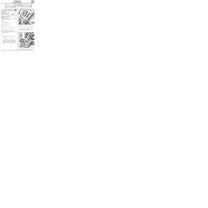
REAR AXLE
88507-2R2
30-5")

30
DIMENSIONSTIGHTENING TORQUES
Bleed screw
Hoses for front calipers
Hoses on rear suspension arm
Rear wheel cylinder supply
Master cylinder outlets
Compensator i")

Diameter of wheel cylinders
Diameter of discs
Thickness of discs
Minimum disc thickness
Pad thickness (including backing)
Minimum pad thickness (including backing)
Maximum disc ru")
 23
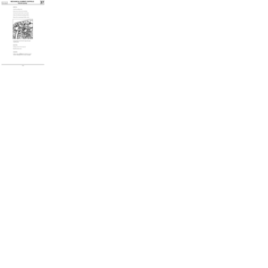
Rear anti-roll bar specifications
Rear suspension bar specifications
VEHICLE TYPEFC0X
KC0XFC0X
KC0X
DIAMETER")


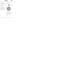
REMOVAL
Put the")

 ,
- the ball joint.
REFITTING
Note : ensure the plastic protective washer ( A ) is
present on the low")