1997 MERCEDES-BENZ ML500 maintenance
[x] Cancel search: maintenancePage 3474 of 4133

Fig. 186: Identifying External Torx Set (001 589 76 09 00)
MAINTENANCE
REPLACE DUST FILTER FOR HEATIN G/AIR CONDITIONING - AP83.00-P-8381GH
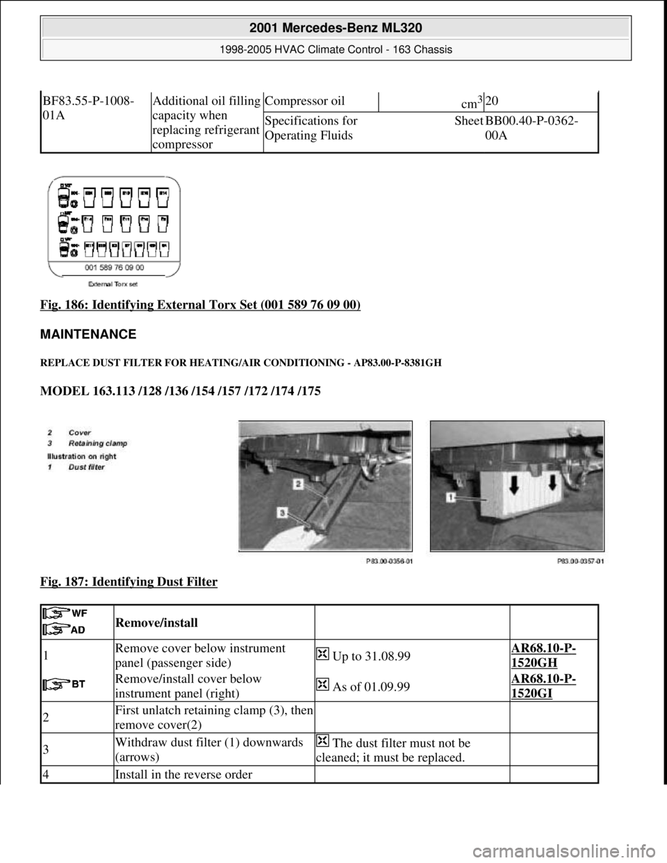
MODEL 163.113 /128 /136 /154 /157 /172 /174 /175
Fig. 187: Identifying Dust Filter
BF83.55-P-1008-
01AAdditional oil filling
capacity when
replacing refrigerant
compressorCompressor oilcm3 20
Specifications for
Operating FluidsSheetBB00.40-P-0362-
00A
Remove/install
1Remove cover below instrument
panel (passenger side) Up to 31.08.99AR68.10-P-
1520GH
Remove/install cover below
instrument panel (right) As of 01.09.99AR68.10-P-
1520GI
2First unlatch retaining clamp (3), then
remove cover(2)
3Withdraw dust filter (1) downwards
(arrows) The dust filter must not be
cleaned; it must be replaced.
4Install in the reverse order
2001 Mercedes-Benz ML320
1998-2005 HVAC Climate Control - 163 Chassis
me
Saturday, October 02, 2010 3:23:19 PMPage 230 © 2006 Mitchell Repair Information Company, LLC.
Page 3592 of 4133

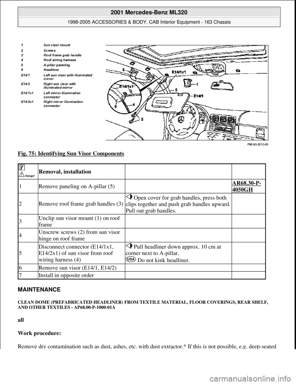
Fig. 75: Identifying Sun Visor Components
MAINTENANCE
CLEAN DOME (PREFABRICATED HEADLINER) FROM TEXTILE MATERIAL, FLOOR COVERINGS, REAR SHELF,
AND OTHER TEXTILES - AP68.00-P-1000-01A
all
Work procedure:
Remove dr
y contamination such as dust, ashes, etc. with dust extractor.* If this is not possible, e.g. deep-seated
Removal, installation
1Remove paneling on A-pillar (5) AR68.30-P-
4050GH
2Remove roof frame grab handles (3)
Open cover for grab handles, press both
clips together and push grab handles upward.
Pull out grab handles.
3Unclip sun visor mount (1) on roof
frame
4Unscrew screws (2) from sun visor
hinge on roof frame
5
Disconnect connector (E14/1x1,
E14/2x1) of sun visor from roof
wiring harness (4) Pull headliner down approx. 10 cm at
corner next to A-pillar.
Do not kink headliner.
6Remove sun visor (E14/1, E14/2)
7Install in opposite order
2001 Mercedes-Benz ML320
1998-2005 ACCESSORIES & BODY, CAB Interior Equipment - 163 Chassis
me
Saturday, October 02, 2010 3:35:22 PMPage 74 © 2006 Mitchell Repair Information Company, LLC.
Page 3835 of 4133

SI18.00-P-0010A
Service Information: oil sludge
26.3.01
ENGINE
111 in MODELS 124, 163, 170, 202, 203, 208, 210
ENGINE
112 in MODELS 129, 163, 170, 202, 203, 208, 210, 220
ENGINE
112, 113 in MODEL 463
ENGINE
113 in MODELS 129, 163, 202, 208, 210, 215, 220
ENGINE
137 in MODEL 215, 220
ENGINE
166 in MODEL 168
Oil sludging in gasoline engines with ASSYST maintenance
system
Recently we have determined that time and time again oil
sludging occurs in gasoline engines with an ASSYST maintenance
system.
Oil sludging can lead to the following complaints:
D
engine oil consumption
D
engine smoke (white/blue)
D
influencing of oil level indicator
D
clogged oil filter, engine oil thickened like jelly
D
Check engine lamp illuminated
D
oil sludge visible during assembly job, e.g. in oil filter, in cylinder
head covers, condensation sludging
(engine 166) etc.
-----------------------------------------------------------------------------------------
The following list of causes may lead individually or as a combination
to engine oil sludging:
D
Crankcase ventilation inoperable, function orifices, bores,
passages in cylinder head cover, cylinder head, crankcase etc.
are mechanically sealed. A nonfunctioning crankcase
ventilation boosts loads on the engine oil through organic
nitrates. The risk of oil sludging increases.
The mechanical condition of the engine is always to be
checked, i.e. all engine oil drain orifices on the cylinder head
and crankcase and all crankcase ventilation ducts must be free
of obstacles. Crankcase breather lines may not be kinked.
Check the ventilation bores in the cylinder head covers.
-----------------------------------------------------------------------------------------
D
The engine oil used does not comply with the specifications in
Sheet 229.1 or 229.3 of the Specifications for Service Products.
The additive process, e.g. dirt-carrying capability, neutralization
capability and oxidation resistance as well as the quality of the
base stock influence sludging time.
Use of engine oils with best possible resistance to formation of
sludge, i.e. use only tested and approved engine oils (from
Sheet 229.1 or 229.3). The best protection is afforded by the
engine oils on Sheet 229.3, which fulfill more stringent
specifications with regard to preventing sludge and deposits
(see Sheet 221.0, page 11). These oils have a distinctly better
anti-sludge characteristic than other engine oils.
D
Sludging after adding a fuel or engine oil special additive.
Do not use fuel or engine oil special additives. More information
hereto is available on Sheet 219.0 of the Specifications for
Service products. Reference to customer not to use special
additives.
D
Engine oil change not performed according to ASSYST
specifications. At driven distances
exceeding > approx. 3000 km, engine oil sludging may occur.
-----------------------------------------------------------------------------------------
Comply with engine oil and filter change as under ASSYST
specifications. Observe remaining distance.
D
Fuel grade lies outside standard (regionally contingent). If
contaminated, deficient fuel is used, then engine oil sludging
may occur even where approved engine oil is used.
Operation with fuel, e.g. as under DIN EN 228. Clarify refueling
behavior of customer. If engine operation regional, is
temporarily possible with deficient oil only, then the startup
distance has to be individually reduced, i.e. the oil change
temporarily performed at an interval of, e.g. 10,000 km.
D
Radiator antifreeze penetration into engine oil, e.g. through an
internal engine leak (cylinder head gasket, casting porosity).
The engine oil sludges within a short period. The crankcase
ventilation clogs up and stops functioning. Condensation
sludging clogs up the oil separator cells
(engine 166).
Rectify coolant leakage. Clean all sludged engine parts, in
particular the crankcase ventilation parts. If the occurrence
repeats, and casting porosity is suspected, e.g. replace
crankcase.
-----------------------------------------------------------------------------------------
Copyright DaimlerChrysler AG 20.05.2006 CD-Ausgabe G/10/04 . This WIS print-out will not be recorde
d by Modification services.
Page 1
Page 3836 of 4133

Measures for slightly sludged engine:
Oil and filter change. Purge engine, i.e. normal engine operation
in neutral, or while driving, using oil from Sheet 229.3, 228.3, or
228.5. Drain off scavenging oil after purging process (approx. 1
hour). Repeat purging process if necessary. Refill using engine oil
from Sheet 229.3, or 229.1. The first oil change after clearing the
sludge should be performed after approx. 10,000 km or beforehand;
when doing so use engine oil from Sheet 229.3.
Measures for severely sludged engine:
Engines with severe oil sludging and caking onto engine parts
and into bores have to be dismantled and mechanically cleaned.
Tough sludge residue must not enter the clean side of the oil circuit,
as otherwise, e.g. the piston oil spray and the hydraulic
compensation elements may have their functionality impaired. Refill
using engine oil from Sheet 229.3, or 229.1.
The first oil change after sludging should be performed after approx.
10,000 km; when doing so use engine oil from
Sheet 229.3.
Warranty/goodwill regulations
If in combination with engine oil sludging a warranty/goodwill claim is
submitted, then a regular documentation of maintenance must be
presented. The ASSYST printout is to be filed carefully for further
reference.
Oil sludging in combination with an exceeded oil change interval, or
because of special additives in the fuel/engine oil are costs to be
borne by the customer.
Copyright DaimlerChrysler AG 20.05.2006 CD-Ausgabe G/10/04 . This WIS print-out will not be recorde
d by Modification services.
Page 2
Page 3876 of 4133

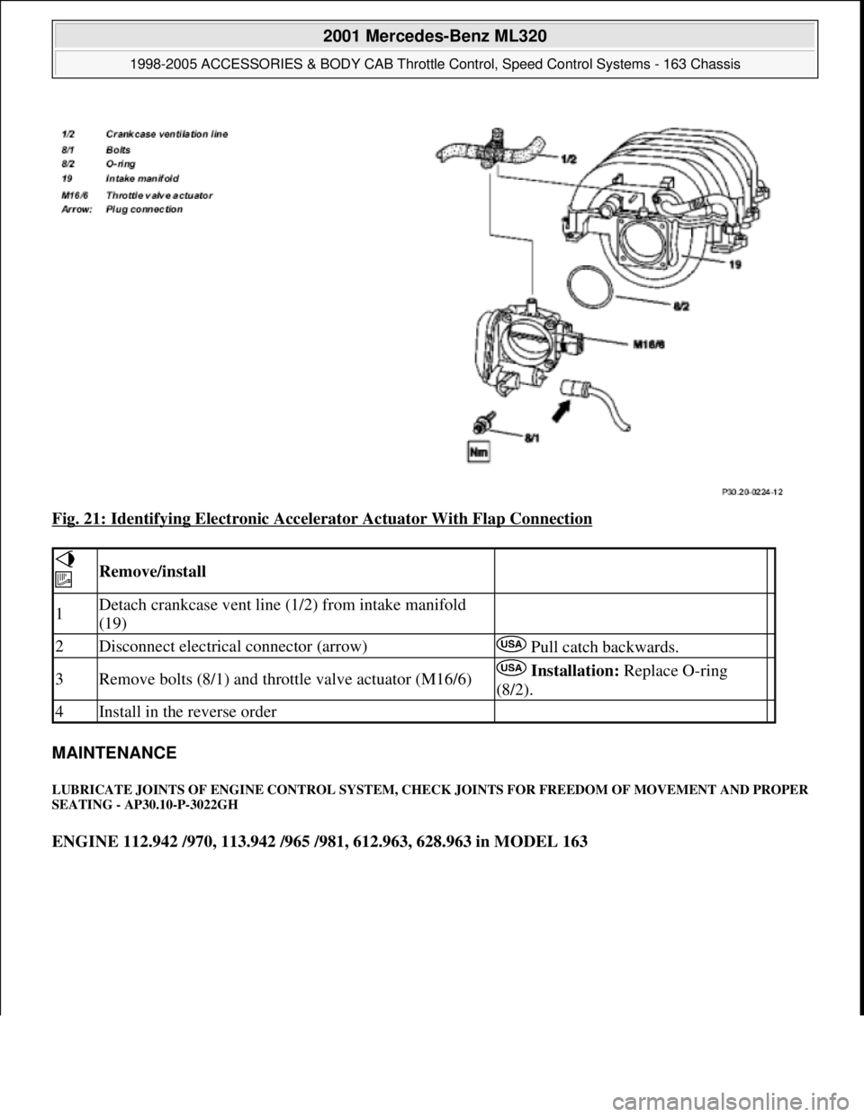
Fig. 21: Identifying Electronic Accelerator Actuator With Flap Connection
MAINTENANCE
LUBRICATE JOINTS OF ENGINE CONTROL SYSTEM, CHECK JOINTS FOR FREEDOM OF MOVEMENT AND PROPER
SEATING - AP30.10-P-3022GH
ENGINE 112.942 /970, 113.942 /965 /981, 612.963, 628.963 in MODEL 163
Remove/install
1Detach crankcase vent line (1/2) from intake manifold
(19)
2Disconnect electrical connector (arrow) Pull catch backwards.
3Remove bolts (8/1) and throttle valve actuator (M16/6) Installation: Replace O-ring
(8/2).
4Install in the reverse order
2001 Mercedes-Benz ML320
1998-2005 ACCESSORIES & BODY CAB Throttle Control, Speed Control Systems - 163 Chassis
me
Saturday, October 02, 2010 3:36:28 PMPage 36 © 2006 Mitchell Repair Information Company, LLC.
Page 3935 of 4133

Rear axle shock absorber
Wheel location
REMOVAL & INSTALLATION
INSTALLING PINCH NUT ON REAR STABILIZER BAR CONNECTING ROD BOLT - SM32.35-P-0001A
MODEL 163.154 #A as of 000001 up to 014254
Vehicles within the Effective Serial Number Range, must have the following work performed during next
scheduled maintenance or service. Install pinch nut to ensure proper tightening torque of rear stabilizer bar
mounting.
Damage code for warranty/goodwill claim: 32 920 07
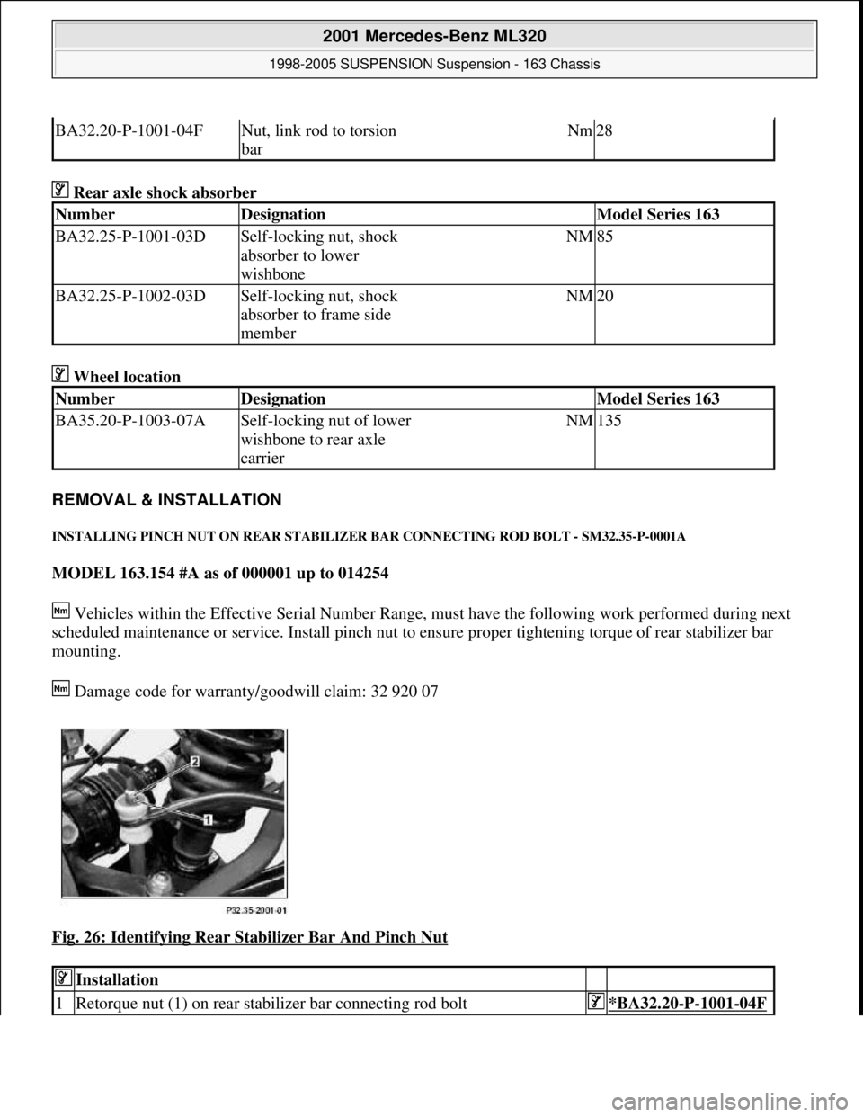
Fig. 26: Identifying Rear Stabilizer Bar And Pinch Nut
BA32.20-P-1001-04FNut, link rod to torsion
barNm28
NumberDesignationModel Series 163
BA32.25-P-1001-03DSelf-locking nut, shock
absorber to lower
wishboneNM85
BA32.25-P-1002-03DSelf-locking nut, shock
absorber to frame side
memberNM20
NumberDesignationModel Series 163
BA35.20-P-1003-07ASelf-locking nut of lower
wishbone to rear axle
carrierNM135
Installation
1Retorque nut (1) on rear stabilizer bar connecting rod bolt*BA32.20-P-1001-04F
2001 Mercedes-Benz ML320
1998-2005 SUSPENSION Suspension - 163 Chassis
me
Saturday, October 02, 2010 3:37:36 PMPage 27 © 2006 Mitchell Repair Information Company, LLC.
Page 3990 of 4133

8
Install spacer ring (2) and screw on union nut
(1) as far as the stop.
Counterhold valve body (3) using
installation tool for tire pressure monitor or pin
4
2 mm (4) in drill hole (arrow).
Installation tool for tire pressure monitor
*WH58.30-Z-1040-06A
9
Tighten union nut (1).
Secure valve body (2) using installation
tool for tire pressure monitor or pin
4
2 mm
(4), to prevent it from turning
After tightening, pull installation tool for
tire pressure monitor or pin
4
2 mm (4) out of
valve body (3). Danger of damage to tire.
Union nut to valve body
*BA40.15-P-1001-01A
Installation tool for tire pressure monitor
*WH58.30-Z-1040-06A
10
Press RPM wheel sensor gently into drop
center of rim and tighten bolt (5).
Internal torx bolt, wheel sensor to valve
body
*BA40.15-P-1002-01A
11
Note ID code (b) of new TPM wheel sensor.
It is advisable to record the code in the
owner's manual or maintenance booklet.
Initialization
12
Teach in new TPM wheel sensor in TPM
control unit using STAR DIAGNOSIS.
Diagnosis system STAR DIAGNOSIS
*WE58.40-Z-1013-06A
13
Activate the tire pressure monitoring system
Model 211
AR54.30-P-1000-02RAT
Model 230
AR54.30-P-1000-02RAR
Model 240
AR54.30-P-1000-02RAH
n
Tire pressure monitor (TPM), activation
Model 210
GF40.15-P-0001-02A
Model 215, 220 up to 30.9.00
GF40.15-P-0001-02B
Model 215, 220 as of 01.10.00 up to 31.05.01
GF40.15-P-0001-02C
Models 215, 220 as of 01.06.01 up to 31.08.02
GF40.15-P-0001-02D
Model 215, 220 as of 01.09.02
GF40.15-P-0001-02E
Tire pressure monitoring
Number
Designation
Model
210, 211,
215, 220,
230, 240
BA40.15-P-1001-01A
Union nut to valve body
Nm
4
BA40.15-P-1002-01A
Bolt, wheel sensor to valve body
Nm
4
Commercially available tools
(see Workshop Equipment Manual)
Number
Designation
Make (e. g.)
Order number
WH58.30-Z-1040-06A
Installation tool for tire pressure control
Alligator Ventilfabrik
GmbH
Postfach 1120
D-89526 Giengen
232540
Workshop equipment/MB testers
(see Workshop Equipment Manual)
WE58.40-Z-1013-06A
STAR DIAGNOSIS Compact diagnosis system for passenger cars, order number 6511 1801 00
Copyright DaimlerChrysler AG 06.07.2006 CD-Ausgabe G/10/04 . This WIS print-out will not be recorde
d by Modification services.
Page 2