1997 MERCEDES-BENZ ML500 maintenance
[x] Cancel search: maintenancePage 1116 of 4133
312 Technical termsEngine oil viscosity
Measurement for the inner friction (vis-
cosity) of the oil at different tempera-
tures. The higher the temperature an
oil can tolerate without becoming thin,
or the lower the temperature it can tol-
erate without becoming viscous, the
better the viscosity.
ESP
(E
lectronic S
tability Pr
ogram)
Improves vehicle handling and direc-
tional stability.
ETD
(E
mergency T
ensioning D
evice)
Device which deploys in certain frontal
and rear collisions exceeding the sys-
tem's threshold to tighten the seat
belts.
->SRSFSS
(F
lexible S
ervice S
ystem)
Service indicator in the speedometer
display that informs the driver when
the next vehicle maintenance service is
due.
Gear range
Number of gears which are available to
the automatic transmission for shifting.
The automatic gear shifting process
can be adapted to specific operating
conditions using the gear selector
lever.
GPS
(G
lobal P
ositioning S
ystem)
Satellite-based system for relaying
geographic location information to and
from vehicles equipped with special re-
ceivers. Employs CD or DVD digital
maps for navigation.GAWR
(G
ross A
xle W
eight R
ating)
The GAWR is the maximum permissible
axle weight. The gross vehicle weight
on each axle must never exceed the
GAWR for the front and rear axle indi-
cated on the certification label located
on the driver’s door pillar.
GVW
(G
ross V
ehicle W
eight)
The GVW comprises the weight of the
vehicle including fuel, tools, spare
wheel, installed accessories, passen-
gers and cargo. The GVW must never
exceed the GVWR, indicated on the
certification label located on the driv-
er’s door pillar.
Page 1133 of 4133

329 Index
Lighting 107
Automatic headlamp mode 108
Cargo compartment 114
Combination switch 110
Daytime running lamp mode 109
Door entry lamps 113
Front fog lamps 111
High beam flasher 110
High beams 110
Instrument cluster illumination 116
Interior 112
Locator lighting 110
Night security illumination 109
Limiting the gear range 121
Limp Home Mode 124
Line of fall 313
Loading 157
Cargo area cover blind* 161
Cargo floor plates 162
Cargo tie-down rings 158
Hooks 159
Instructions 157, 158
Partition net* 159
Roof rack 163Split rear bench seat 99
Trailer 208
Locator lighting 110
Lock button 313
Locking 88
Automatic while driving 93
Centrally from inside 94
Fuel filler flap 214
Global 89
Vehicle in an emergency 262
Locking knobs 32
Loss of keys 90
Loss of Service and Warranty Information
Booklet 291
Low beam headlamps
Replacing bulbs 266, 268
Switching on 48
Low engine oil level
Indicator lamp 253
LOW RANGE - 4-ETS 80
LOW RANGE - ABS 77LOW RANGE - ESP 81
LOW RANGE mode 125
Low washer system fluid level
Indicator lamp 253
Lowering
Vehicle 276
M
Main dimensions 298
Maintenance 12
Display messages 256
Manual operations
Fuel filler flap 263
Interior lighting control 113
Locking the vehicle 262
Sliding/pop-up roof* 265
Unlocking the driver’s door 261
Unlocking transmission selector
lever 264
Page 1358 of 4133
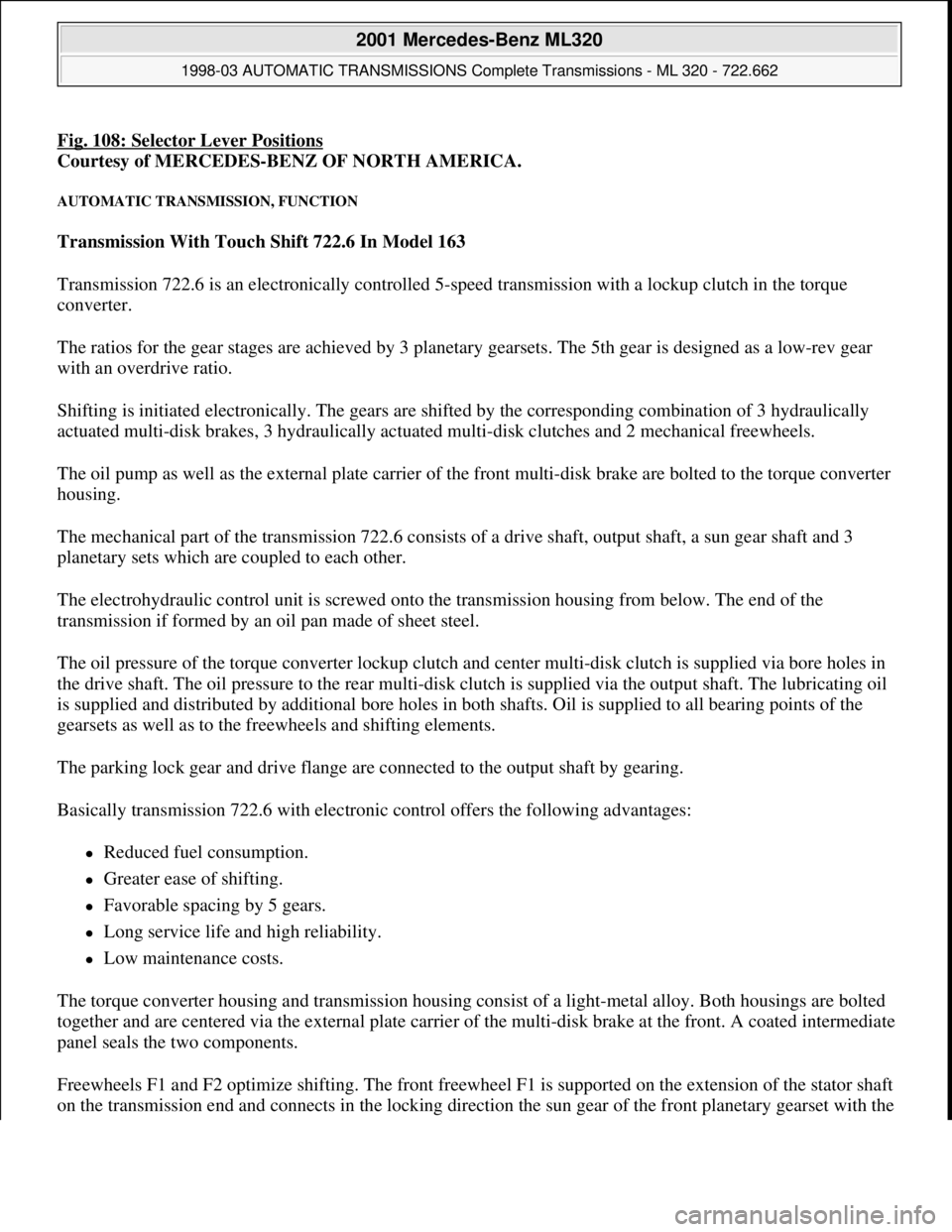
Fig. 108: Selector Lever Positions
Courtesy of MERCEDES-BENZ OF NORTH AMERICA.
AUTOMATIC TRANSMISSION, FUNCTION
Transmission With Touch Shift 722.6 In Model 163
Transmission 722.6 is an electronically controlled 5-speed transmission with a lockup clutch in the torque
converter.
The ratios for the gear stages are achieved by 3 planetary gearsets. The 5th gear is designed as a low-rev gear
with an overdrive ratio.
Shifting is initiated electronically. The gears are shifted by the corresponding combination of 3 hydraulically
actuated multi-disk brakes, 3 hydraulically actuated multi-disk clutches and 2 mechanical freewheels.
The oil pump as well as the external plate carrier of the front multi-disk brake are bolted to the torque converter
housing.
The mechanical part of the transmission 722.6 consists of a drive shaft, output shaft, a sun gear shaft and 3
planetary sets which are coupled to each other.
The electrohydraulic control unit is screwed onto the transmission housing from below. The end of the
transmission if formed by an oil pan made of sheet steel.
The oil pressure of the torque converter lockup clutch and center multi-disk clutch is supplied via bore holes in
the drive shaft. The oil pressure to the rear multi-disk clutch is supplied via the output shaft. The lubricating oil
is supplied and distributed by additional bore holes in both shafts. Oil is supplied to all bearing points of the
gearsets as well as to the freewheels and shifting elements.
The parking lock gear and drive flange are connected to the output shaft by gearing.
Basically transmission 722.6 with electronic control offers the following advantages:
Reduced fuel consumption.
Greater ease of shifting.
Favorable spacing by 5 gears.
Long service life and high reliability.
Low maintenance costs.
The torque converter housing and transmission housing consist of a light-metal alloy. Both housings are bolted
together and are centered via the external plate carrier of the multi-disk brake at the front. A coated intermediate
panel seals the two components.
Freewheels F1 and F2 optimize shifting. The front freewheel F1 is supported on the extension of the stator shaft
on the transmission end and connects in the lockin
g direction the sun gear of the front planetary gearset with the
2001 Mercedes-Benz ML320
1998-03 AUTOMATIC TRANSMISSIONS Complete Transmissions - ML 320 - 722.662
me
Saturday, October 02, 2010 3:15:28 PMPage 189 © 2006 Mitchell Repair Information Company, LLC.
Page 1817 of 4133
Front seats
Seat belts/emergency tensioning retractors
MAINTENANCE
CHECK SETTING OF HIGH BEAM - AP82.10-P-8260-02A
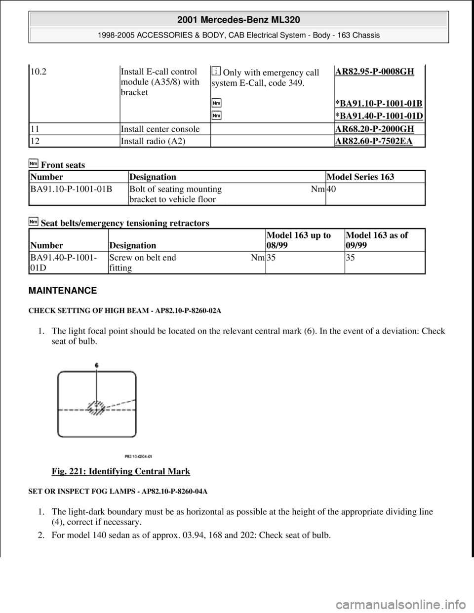
1. The light focal point should be located on the relevant central mark (6). In the event of a deviation: Check
seat of bulb.
Fig. 221: Identifying Central Mark
SET OR INSPECT FOG LAMPS - AP82.10-P-8260-04A
1. The light-dark boundary must be as horizontal as possible at the height of the appropriate dividing line
(4), correct if necessary.
2. For model 140 sedan as of approx. 03.94, 168 and 202: Check seat of bulb.
10.2Install E-call control
module (A35/8) with
bracket Only with emergency call
system E-Call, code 349.AR82.95-P-0008GH
*BA91.10-P-1001-01B
*BA91.40-P-1001-01D
11Install center console AR68.20-P-2000GH
12Install radio (A2) AR82.60-P-7502EA
NumberDesignationModel Series 163
BA91.10-P-1001-01BBolt of seating mounting
bracket to vehicle floorNm40
NumberDesignation
Model 163 up to
08/99Model 163 as of
09/99
BA91.40-P-1001-
01DScrew on belt end
fittingNm3535
2001 Mercedes-Benz ML320
1998-2005 ACCESSORIES & BODY, CAB Electrical System - Body - 163 Chassis
me
Saturday, October 02, 2010 3:30:10 PMPage 322 © 2006 Mitchell Repair Information Company, LLC.
Page 2061 of 4133
AP40.10-P-4051Z
Check tires for damage and cracks
MODEL
123, 124, 126, 129, 140, 163, 168, 170, 171, 201, 202, 203, 208, 209, 210, 211, 215, 220, 230, 240, 414
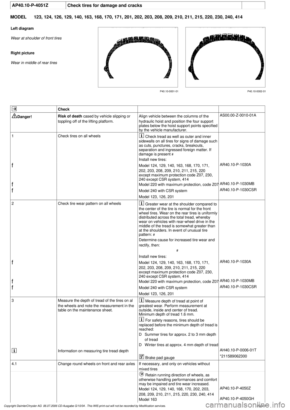
P40.10-0002-01
P40.10-0001-01
Left diagram
Wear at shoulder of front tires
Right picture
Wear in middle of rear tires
Check
Danger!
Risk of death
cased by vehicle slipping or
toppling off of the lifting platform.
Align vehicle between the columns of the
hydraulic hoist and position the four support
plates below the hoist support points specified
by the vehicle manufacturer.
AS00.00-Z-0010-01A
1
Check tires on all wheels
Check tread as well as outer and inner
sidewalls on all tires for signs of damage such
as cuts, punctures, cracks, breakouts,
separation and ingressed foreign matter. If
damage is present
#
Install new tires:
f
Model 124, 129, 140, 163, 168, 170, 171,
202, 203, 208, 209, 210, 211, 215, 220
except maximum protection code Z07, 230,
240 except CSR system, 414
AR40.10-P-1030A
f
Model 220 with maximum protection, code Z07
AR40.10-P-1030MB
f
Model 240 with CSR system
AR40.10-P-1030CSR
Model 123, 126, 201
2
Check tire wear pattern on all wheels
Greater wear at the shoulder compared to
the center of the tire is normal for the front
wheel tires. Wear on the rear tires is uniformly
distributed across the total tread, whereby
wear on vehicles with rear-wheel drive in the
middle of the tread is somewhat greater than
at the shoulders. In event of unusual tire
pattern:
#
Determine cause for increased tire wear and
rectify, then:
#
Install new tires:
f
Model 124, 129, 140, 163, 168, 170, 171,
202, 203, 208, 209, 210, 211, 215, 220
except maximum protection code Z07, 230,
240 except CSR system, 414
AR40.10-P-1030A
f
Model 220 with maximum protection, code Z07
AR40.10-P-1030MB
f
Model 240 with CSR system
AR40.10-P-1030CSR
Model 123, 126, 201
3
Measure the depth of tread of the tires on al
the wheels and note the measurement in the
table on the maintenance sheet.
Measure depth of tread at point of
greatest wear. Perform measurement at
outside, inside and center of tread.
Minimum depth of tread 1.6 mm.
For safety reasons, tires should be
replaced before the minimum depth of tread is
reached:
D
Summer tires for approx. 2 to 3 mm depth
of tread
D
Winter tires at approx. 4 mm depth of tread
Information on measuring tire tread depth
AH40.10-P-0006-01T
Brake pad gauge
*211589062300
4.1
Change round wheels on front and rear axles
If necessary, and only on vehicles without
mixed tires
Retain running direction of wheels, as
otherwise handling performances and comfort
may be impaired and tire wear increased.
Model 124, 129, 140, 168, 170, 202, 203,
208, 209, 210, 211, 215, 220, 230, 240, 414
AP40.10-P-4050Z
Model 163
AP40.10-P-4050GH
Copyright DaimlerChrysler AG 06.07.2006 CD-Ausgabe G/10/04 . This WIS print-out will not be recorde
d by Modification services.
Page 1
Page 2066 of 4133

GF54.30-P-2004A
Control buttons, location/task
24.10.96
MODEL
129, 140 as of 1.6.96,
163, 170
The instrument cluster has two control buttons which are on the left
or right next to the speedometer.
The
right control button
is used to adjust the time (refer to Owner's
Manual).
-----------------------------------------------------------------------------------------
The
left control button
is used
D
to regulate the instrument illumination
D
to activate the display illumination
D
to reset the trip odometer display
D
to operate the maintenance display (model 170 only bis 05.97)
D
to operate the Active Service System ASSYST (as of 06.97)
-----------------------------------------------------------------------------------------
n
Purpose/function of terminal 58d, instrument
display illumination
Engines 112, 113, 611 (engines with oil
sensor)
GF54.30-P-3008A
n
Electronic clock
GF54.30-P-3011A
n
Active Service System (ASSYST)
GF00.20-P-0003-01A
Operating instructions, resetting
Model 210 as of 01.03.97 with engines M111,
OM 602, OM 604, OM 605 and
OM 606
As of 06/97 models 129, 140, 170, 202 except
engines 112, 113, 611
(valid for engines with oil level switch)
GF00.20-P-0003-01B
Copyright DaimlerChrysler AG 05.06.2006 CD-Ausgabe G/10/04 . This WIS print-out will not be recorde
d by Modification services.
Page 1
Page 2228 of 4133
GF54.30-P-3011A
Electronic clock, location/function
24.10.96
MODEL
129, 140 as of 1.6.96,
163, 168, 170,
202 as of 1.8.96,
208 up to 31.7.99,
210 as of 1.6.96 up to 30.6.99
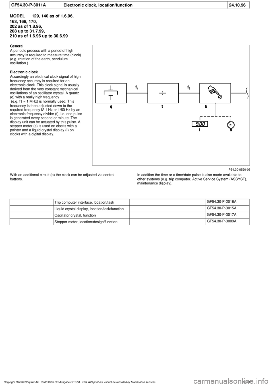
P54.30-0520-06
General
A periodic process with a period of high
accuracy is required to measure time (clock)
(e.g. rotation of the earth, pendulum
oscillation.)
Electronic clock
Accordingly an electrical clock signal of high
frequency accuracy is required for an
electronic clock. This clock signal is usually
derived from the very constant mechanical
oscillations of an oscillator crystal. A quartz
(q) with a really high frequency
(e.g. f
1
= 1 MHz) is normally used. This
frequency is then adjusted down to the
required frequency f
2
1 Hz or 1/60 Hz by an
electronic frequency divider (t), i.e. one pulse
is generated every second or minute. The
display unit can be actuated by this pulse. A
stepper motor (s) is used on clocks with a
pointer and a liquid crystal display (I) on
clocks with a digital display.
With an additional circuit (b) the clock can be adjusted via control
buttons.
In addition the time or a time/date pulse is also made available to
other systems (e.g. trip computer, Active Service System (ASSYST),
maintenance display).
Trip computer interface, location/task
GF54.30-P-2016A
Liquid crystal display, location/task/function
GF54.30-P-3015A
Oscillator crystal, function
GF54.30-P-3017A
Stepper motor, location/design/function
GF54.30-P-3009A
Copyright DaimlerChrysler AG 05.06.2006 CD-Ausgabe G/10/04 . This WIS print-out will not be recorde
d by Modification services.
Page 1
Page 2369 of 4133
3. Special directives
3.1 Installation of factory-new repl acement engine of identical type
a. If a factory-new engine is installed and an engine num ber is required (e.g. vehicle registered
outside of the Federal Republic of Germany), the number of the factory-new engine must be
ground off and the number of the originally instal led engine of identical type stamped in its
place.
b. If the factory-new engine is fitted with an e ngine type plate (older car engines) and it is
necessary to indicate an engine number in the ve hicle documents, in this case take the engine
type plate off the engine remove d and affix it at the same point on the engine of identical
type to be installed.
3.2 Installation of recondition ed engine of identical type
a. The reconditioned engine plate must not be re moved either from the reconditioned engine to
be installed, nor from the engine removed, if the latter was a reconditioned engine.
b. If the engine removed is fitt ed with an engine type plate (older car engines) and it is
necessary to indicate an engine number in the vehicle documents, the engine type plate then
has to be taken off the engine removed and a ffixed at the same point to the reconditioned
engine to be installed. This plate should be affixed in addition to the reconditioned engine
plate.
In the event that a vehicle owner has problems on the occasion of vehicle checks or when crossing
international frontiers be cause of the lack of an engine num ber, the workshop in question may in
certain circumstances be held liable.
After replacing an engine , the engine number has to be altere d in the vehicle maintenance booklet
and on the vehicle data cards as well as in the re pair customer file. These documents should clearly
show which engine is installed in the vehicl e in order to ensure smooth parts service.
In addition, the copy of the vehicle data card which is held at the Parts Department of the relevant
Branch or Importer shoul d also be altered.
3.3 Model designation id entification of crankcases and shortblocks
Crankcases and shortblocks available in the parts sector are not provided with an engine model designation
identification and also not with an engine number.
To make it possible to identify the engine on the occas ion of vehicle inspections (e.g. by an inspection authority
when a vehicle is taken out of service or at the Customs on the occasion of importation of vehicle), the
workshop carrying out the repairs has to stamp the engine model designation in the crankcase or the shortblock
in the space provided fo r the engine number.
Example:
Type Engine model designation
201.024 102.962
2001 Mercedes-Benz ML320
1998-2005 ENGINE Complete engine - 163 Chassis
me
Saturday, October 02, 2010 3:17:55 PMPage 13 © 2006 Mitchell Repair Information Company, LLC.