Page 2138 of 4133
GF54.21-P-4106GH
Extended activity module position/task
23.6.99
MODEL
163
P54.21-2057-11
N10/1
Extended activitiy module
The extended activity module in combination with the new drive
authorization system (DAS (N10/ 1- n1)) represents an extension of
the
A
ll-
A
ctivity
M
odule. In addition, the extended activity module acts
as a diagnosis gateway for the transfer case, the all-activity module
and as of 1.9.00 for the trip computer control module.
Extended activity module position
The extended activity module is located in the
interior of the vehicle on the left side behind
the instrument cluster.
Extended activity module task
GF54.21-P-4106-01GH
Copyright DaimlerChrysler AG 18.05.2006 CD-Ausgabe G/10/04 . This WIS print-out will not be recorde
d by Modification services.
Page 1
Page 2143 of 4133

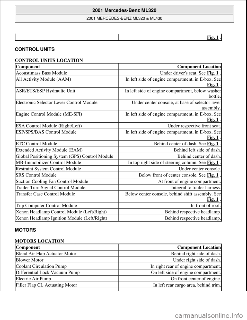
CONTROL UNITS
CONTROL UNITS LOCATION
MOTORS
MOTORS LOCATION
Fig. 1 .
ComponentComponent Location
Acoustimass Bass ModuleUnder driver's seat. See Fig. 1 .
All Activity Module (AAM)In left side of engine compartment, in E-box. See
Fig. 1
.
ASR/ETS/ESP Hydraulic UnitIn left side of engine compartment, below washer
bottle.
Electronic Selector Lever Control ModuleUnder center console, at base of selector lever
assembly.
Engine Control Module (ME-SFI)In left side of engine compartment, in E-box. See
Fig. 1
.
ESA Control Module (Right/Left)Under respective front seat.
ESP/SPS/BAS Control ModuleIn left side of engine compartment, in E-box. See
Fig. 1
.
ETC Control ModuleBehind center of dash. See Fig. 1 .
Extended Activity Module (EAM)Behind left side of dash.
Global Positioning System (GPS) Control ModuleBehind center of dash.
MB-Immobilizer Control ModuleIn top right side of steering column. See Fig. 1 .
Restraint System Control ModuleUnder center console.
SRS Control ModuleBelow front of center console. See Fig. 1 .
Suction Cooling Fan Control ModuleAt front of engine compartment.
Trailer Turn Signal Control ModuleIntegral to trailer harness.
Transfer Case Control ModuleBelow center console, behind shift assembly. See
Fig. 1
.
Trip Computer Control ModuleIn front of roof.
Xenon Headlamp Control Module (Left/Right)Behind respective headlamp.
Xenon Headlamp Ignition Module (Left/Right)Behind respective headlamp.
ComponentComponent Location
Blend Air Flap Actuator MotorBehind right side of dash.
Blower MotorUnder right side of dash.
Coolant Circulation PumpIn right rear of engine compartment.
Differential Lock Vacuum PumpOn left side of engine compartment.
Electric Air PumpOn front center of engine.
Filler Flap CL Actuating MotorIn left rear cargo area, behind trim.
2001 Mercedes-Benz ML320
2001 MERCEDES-BENZ ML320 & ML430
me
Saturday, October 02, 2010 3:21:17 PMPage 3 © 2006 Mitchell Repair Information Company, LLC.
Page 2228 of 4133

GF54.30-P-3011A
Electronic clock, location/function
24.10.96
MODEL
129, 140 as of 1.6.96,
163, 168, 170,
202 as of 1.8.96,
208 up to 31.7.99,
210 as of 1.6.96 up to 30.6.99
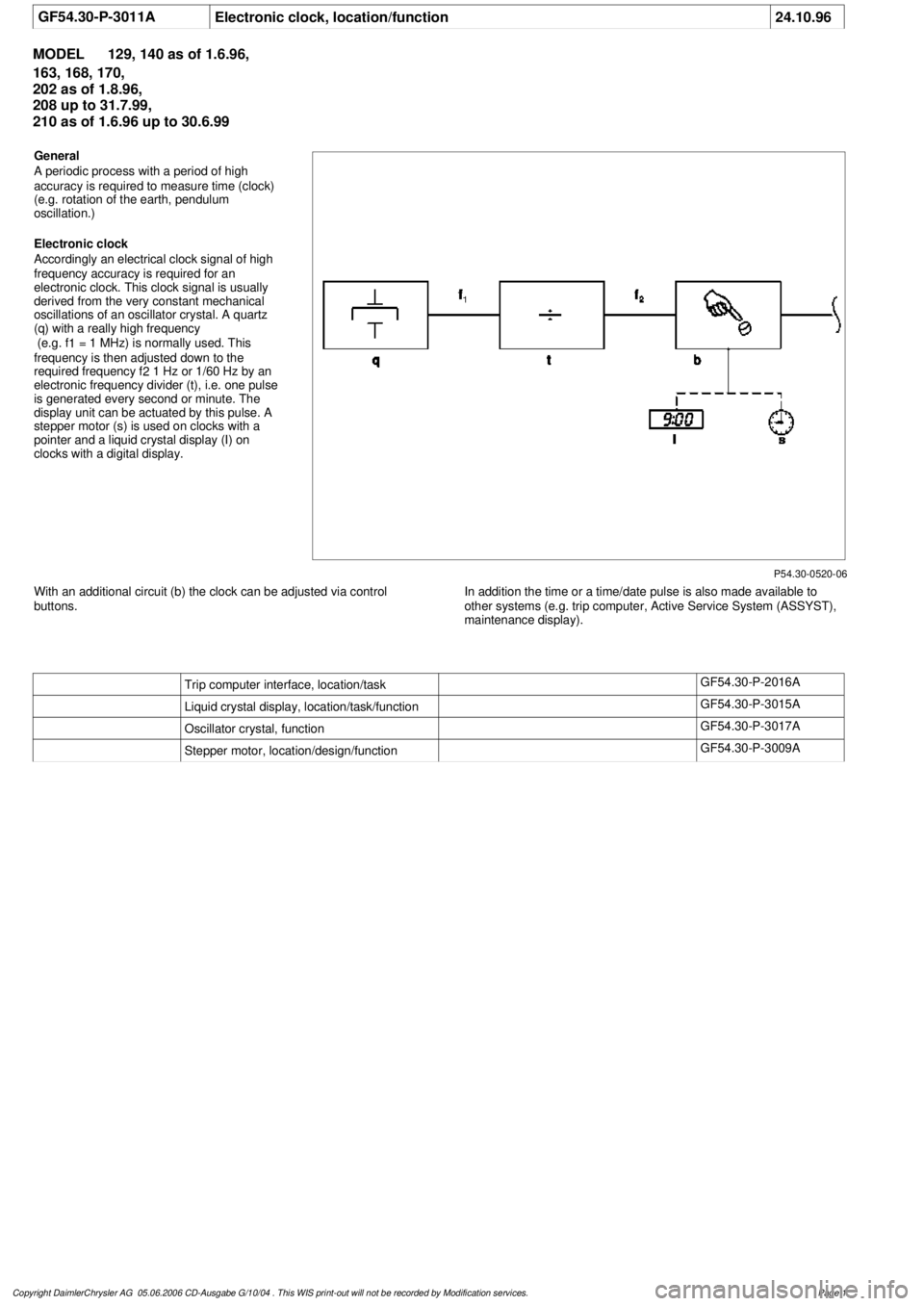
P54.30-0520-06
General
A periodic process with a period of high
accuracy is required to measure time (clock)
(e.g. rotation of the earth, pendulum
oscillation.)
Electronic clock
Accordingly an electrical clock signal of high
frequency accuracy is required for an
electronic clock. This clock signal is usually
derived from the very constant mechanical
oscillations of an oscillator crystal. A quartz
(q) with a really high frequency
(e.g. f
1
= 1 MHz) is normally used. This
frequency is then adjusted down to the
required frequency f
2
1 Hz or 1/60 Hz by an
electronic frequency divider (t), i.e. one pulse
is generated every second or minute. The
display unit can be actuated by this pulse. A
stepper motor (s) is used on clocks with a
pointer and a liquid crystal display (I) on
clocks with a digital display.
With an additional circuit (b) the clock can be adjusted via control
buttons.
In addition the time or a time/date pulse is also made available to
other systems (e.g. trip computer, Active Service System (ASSYST),
maintenance display).
Trip computer interface, location/task
GF54.30-P-2016A
Liquid crystal display, location/task/function
GF54.30-P-3015A
Oscillator crystal, function
GF54.30-P-3017A
Stepper motor, location/design/function
GF54.30-P-3009A
Copyright DaimlerChrysler AG 05.06.2006 CD-Ausgabe G/10/04 . This WIS print-out will not be recorde
d by Modification services.
Page 1
Page 3580 of 4133
Fig. 64: Identifying Caps And Door Sill Molding
PREPARE HEADLINER FOR INSTALLING HANDLES - AR68.30-P-4300-01GH
Models 163.113/136/154/172 up to 31.8.01
When aligning the template, ensure that the arrow is pointing in direction of travel and the correct template
is used for each side.
1. Align template at cutouts provided.
2. Mark cutouts for grab handles.
3. Cut out cutouts for
grab handles.
Remove/install
1Remove cover caps (1) Do not scratch door sill molding.
2Remove screws below caps
3Remove door sill molding (2) Installation: Ensure that sealing rubber is
positioned correctly.
4.1Disconnect connector from electronic
compass Only as of 01.09.00 and with code (245), trip
computer.
5Install in the reverse order
2001 Mercedes-Benz ML320
1998-2005 ACCESSORIES & BODY, CAB Interior Equipment - 163 Chassis
me
Saturday, October 02, 2010 3:35:22 PMPage 62 © 2006 Mitchell Repair Information Company, LLC.
Page 3736 of 4133

AR82.20-P-1100GH
Remove/install front overhead control panel
27.5.97
MODEL
163.113 /128 /136 /154 /157 /172 /174 /175
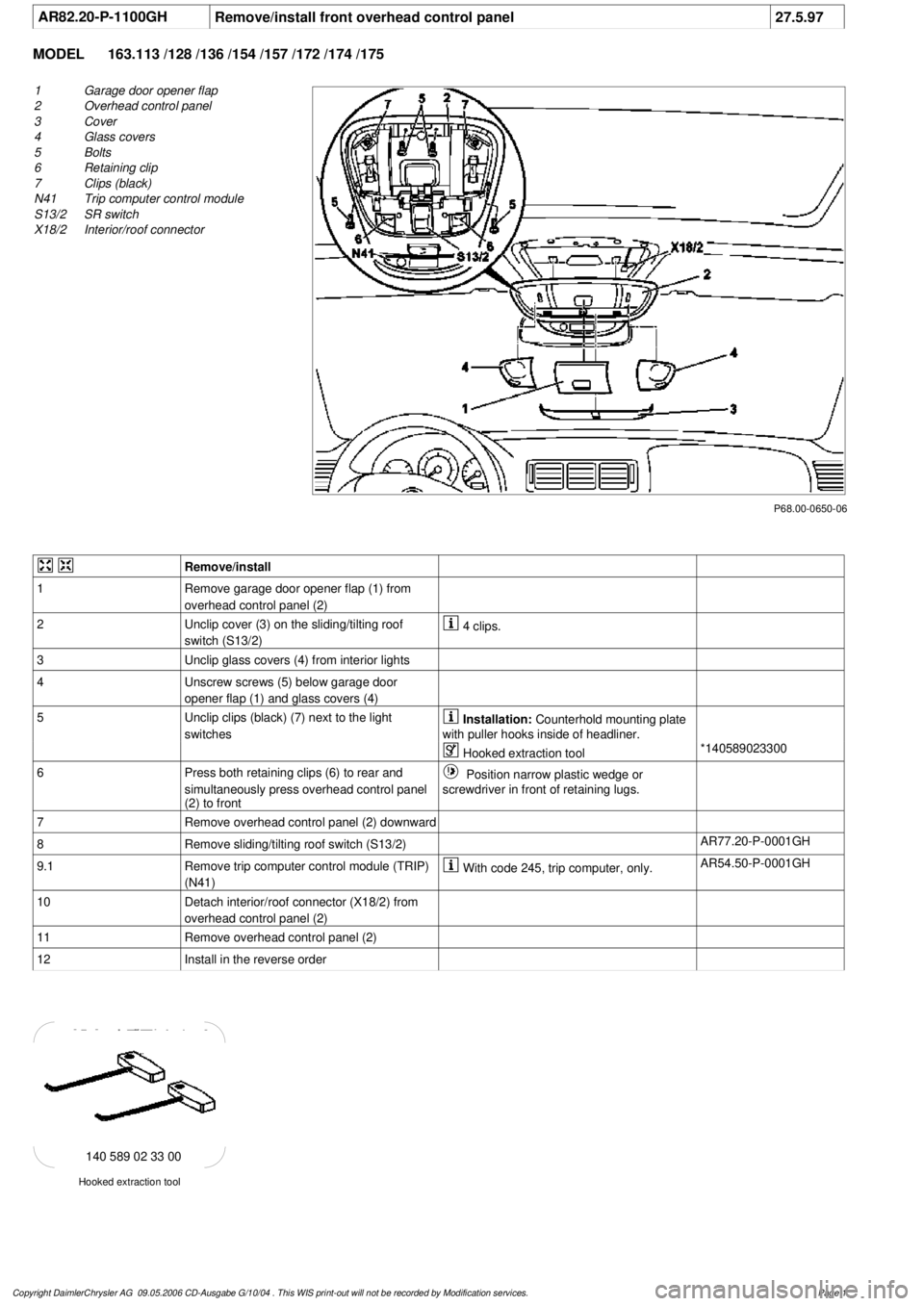
P68.00-0650-06
1
Garage door opener flap
2
Overhead control panel
3
Cover
4
Glass covers
5
Bolts
6
Retaining clip
7
Clips (black)
N41
Trip computer control module
S13/2
SR switch
X18/2
Interior/roof connector
Remove/install
1
Remove garage door opener flap (1) from
overhead control panel (2)
2
Unclip cover (3) on the sliding/tilting roof
switch (S13/2)
4 clips.
3
Unclip glass covers (4) from interior lights
4
Unscrew screws (5) below garage door
opener flap (1) and glass covers (4)
5
Unclip clips (black) (7) next to the light
switches
Installation:
Counterhold mounting plate
with puller hooks inside of headliner.
Hooked extraction tool
*140589023300
6
Press both retaining clips (6) to rear and
simultaneously press overhead control panel
(2) to front
Position narrow plastic wedge or
screwdriver in front of retaining lugs.
7
Remove overhead control panel (2) downward
8
Remove sliding/tilting roof switch (S13/2)
AR77.20-P-0001GH
9.1
Remove trip computer control module (TRIP)
(N41)
With code 245, trip computer, only.
AR54.50-P-0001GH
10
Detach interior/roof connector (X18/2) from
overhead control panel (2)
11
Remove overhead control panel (2)
12
Install in the reverse order
Hooked extraction tool
140 589 02 33 00
Copyright DaimlerChrysler AG 09.05.2006 CD-Ausgabe G/10/04 . This WIS print-out will not be recorde
d by Modification services.
Page 1
Page 3952 of 4133
GF54.50-P-4101GH
Electronic compass, location/purpose/design
24.3.00
MODEL
163 as of 1.9.00 with CODE (245) Trip computer
P54.50-2035-06
B26
Electronic compass
Electronic compass, location
The electronic compass (B26) can be found
below the cover for the trunk sill.
Electronic compass, purpose
GF54.50-P-4101-01GH
Electronic compass, design
The electronic compass (B26) is housed in a
plastic casing. The two measuring coils are
mounted perpendicular to one another on a
circuit board. The 4-pin connector is
connected to the electronic compass (B26)
via a piece of cable.
Copyright DaimlerChrysler AG 18.05.2006 CD-Ausgabe G/10/04 . This WIS print-out will not be recorde
d by Modification services.
Page 1
Page 3953 of 4133
GF54.50-P-4101-01GH
Electronic compass, purpose
n
The electronic compass (B26) determines the current route
of the
vehicle using the
earth's magnetic field
and passes the appropriate
data to the trip computer control module (N41) via a two-wire
interface (RS485).
The compass has a calibration mode to allow the route to be
determined as accurately as possible. In this mode the compass can
be adapted to the magnetic conditions around the vehicle.
Copyright DaimlerChrysler AG 18.05.2006 CD-Ausgabe G/10/04 . This WIS print-out will not be recorde
d by Modification services.
Page 1
Page 3954 of 4133
GF54.50-P-4100-02GH
Trip computer control module, design
n
The trip computer control module (TRIP, N41) consists of the
following components:
D
Electronics unit
D
LCD display
D
Reset button (left button, N41s1)
D
Mode button (right button, N41s2)
D
Inclination sensor (N41b1)
D
Glass breakage sensor (N41b2)
D
CAN interface
D
Alarm bus to all activity module (AAM, N10)
D
as of 1.9.00: Interface (RS 485) to electronic compass (B26)
Copyright DaimlerChrysler AG 18.05.2006 CD-Ausgabe G/10/04 . This WIS print-out will not be recorde
d by Modification services.
Page 1