1997 MERCEDES-BENZ ML500 ESP
[x] Cancel search: ESPPage 3834 of 4133

463
All
-----
1)
Recognition: existing "airbag Off" warning light in center
console.
2)
With HHT functions menu point 5 Coding Reboard child seat. If
only the passenger side airbag is de-activated, then program
menu point Vehicle equipment.
3)
Depending on model and version, unplug one or two
connectors at the passenger side airbag and insert the
corresponding replacement resistors.
4)
Without ACSR, with seat belt force limiter.
Immobilizing passenger side airbag certificate
Model 124, 126, 129, 140, 163 up to VIN
145263, 170, 202, 210
Have customer sign certificate after
immobilization
OF91.60-P-1000-01A
Cancel immobilization
D
To re-activate the passenger side airbag remove the ignition
resistor at the cable.
D
Fit together connector at passenger side airbag.
D
Fit together connector at passenger side ETR (on models fitted
with seat belt force limiter).
D
Use HHT or STAR Diagnosis tool (DAS) to re-program
passenger side airbag and passenger side ETR in the SRS
control module to "YES".
D
Remove sticker on passenger side airbag and render invalid in
Owner's Manual.
D
Complete re-activation on certificate after immobilization.
D
If re-activated, delete de-activation in vehicle documents.
Parts ordering notes
Part no.
Designation
Quantity
140 868 00 50
Ignition resistor (replacement resistor)
as required
140 817 15 20
Sticker (without seat belt force limiter)
2
210 817 20 20
Sticker (with seat belt force limiter)
2
Copyright DaimlerChrysler AG 14.06.2006 CD-Ausgabe G/10/04 . This WIS print-out will not be recorde
d by Modification services.
Page 2
Page 3842 of 4133

ENGINE 119.980 /981 /982 /985
ENGINE 137.970
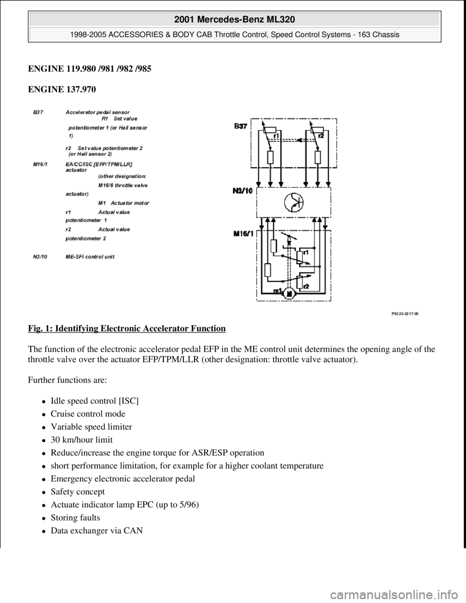
Fig. 1: Identifying Electronic Accelerator Function
The function of the electronic accelerator pedal EFP in the ME control unit determines the opening angle of the
throttle valve over the actuator EFP/TPM/LLR (other designation: throttle valve actuator).
Further functions are:
Idle speed control [ISC]
Cruise control mode
Variable speed limiter
30 km/hour limit
Reduce/increase the engine torque for ASR/ESP operation
short performance limitation, for example for a higher coolant temperature
Emergency electronic accelerator pedal
Safety concept
Actuate indicator lamp EPC (up to 5/96)
Storing faults
Data exchanger via CAN
2001 Mercedes-Benz ML320
1998-2005 ACCESSORIES & BODY CAB Throttle Control, Speed Control Systems - 163 Chassis
me
Saturday, October 02, 2010 3:36:27 PMPage 2 © 2006 Mitchell Repair Information Company, LLC.
Page 3844 of 4133

PEDAL VALUE SENSOR PO SITION - GF30.20-P-4011-01GH
Electronic power control indicator lamp,
location/task/design/functionEngine 119, 120 in Model 129, 140 up to
5/96GF30.20-P-
4012L
Electronic accelerator pe dal emergency running
mode functionEngine 104, 111, 112, 113, 119, 137GF30.20-P-
4026E
30 km/h limit, function
Model 129, 140 with Engine 104,
119.98, 120.98
except GF30.20-P-
4027F
Cruise control (CC) function
With cruise controlGF30.30-P-
0001F
Engine 104 (except HFM sequential
multiport fuel injection/ignition system),
119.98, 120.98
With cruise control
Engine 111, 112, 113, 137GF30.30-P-
0001FA
Variable speed limiter, functionAdditional cruise control function except
GF30.30-P-
3001A
Distronic (DTR), function
Model 220, 215 with code 219a up to
6/00GF30.30-P-
0002K
Model 203, 209, 211, 230 with code
219a
GF30.30-P-
0002KA
Model 215, 220 with code 219a as of
7/00
Pedal value sensor characteristic curve when
reversing function GF30.20-P-
4013E
ASR V control unit location/task/design/function
with code 471 a
Model 129, 140, 202 as of 6/94, 170,
208, 210GF42.40-P-
4500A
ESP control unit location/task/function
with code 472a
Model 129 with Engine 104, 119, 120
Model 140
Model 210 with engine 119
GF42.45-P-
4500A
with code 472a
Model 129 with engine 112, 113
Model 163 up to 8/02, 168, 215
Model 220 (except 220.08/18) Model
202, 208 with engine 112, 113
Model 210 with engine 111, 112, 113
GF42.45-P-
4500B
with code 472a
Model 170 with Engine 111, 112
Model 202, 208 with Engine 111
Model 203
GF42.45-P-
4500C
Model 211, 230GF42.45-P-
4500SL
2001 Mercedes-Benz ML320
1998-2005 ACCESSORIES & BODY CAB Throttle Control, Speed Control Systems - 163 Chassis
me
Saturday, October 02, 2010 3:36:27 PMPage 4 © 2006 Mitchell Repair Information Company, LLC.
Page 3866 of 4133

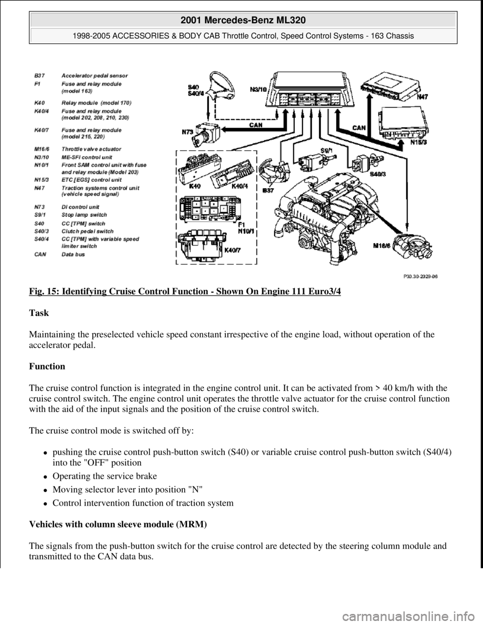
Fig. 15: Identifying Cruise Control Function - Shown On Engine 111 Euro3/4
Task
Maintaining the preselected vehicle speed constant irrespective of the engine load, without operation of the
accelerator pedal.
Function
The cruise control function is integrated in the engine control unit. It can be activated from > 40 km/h with the
cruise control switch. The engine control unit operates the throttle valve actuator for the cruise control function
with the aid of the input signals and the position of the cruise control switch.
The cruise control mode is switched off by:
pushing the cruise control push-button switch (S40) or variable cruise control push-button switch (S40/4)
into the "OFF" position
Operating the service brake
Moving selector lever into position "N"
Control intervention function of traction system
Vehicles with column sleeve module (MRM)
The signals from the push-button switch for the cruise control are detected by the steering column module and
transmitted to the CAN data bus.
2001 Mercedes-Benz ML320
1998-2005 ACCESSORIES & BODY CAB Throttle Control, Speed Control Systems - 163 Chassis
me
Saturday, October 02, 2010 3:36:27 PMPage 26 © 2006 Mitchell Repair Information Company, LLC.
Page 3907 of 4133

AR88.30-P-0200-01GH
Separate detachable body components
Danger!
Risk of poisoning
after inhaling vapors or
swallowing adhesive.
Risk of injury
from
adhesive coming into contact with skin and
eyes
Wear protective respiratory masks,
protective gloves and safety glasses.
Pour adhesive only into suitable and
appropriately marked containers.
AS00.00-Z-0016-01A
Long wedge
115 589 03 59 00
Commercially available tools
(see Workshop Equipment Manual)
Number
Designation
Make (e. g.)
Order number
WH58.30-Z-1010-10A
Cutting tool kit (compressed-air tool + blades)
Europe:
The Barn
Holly Tree Farm
Holmes Chapel Road
Lower Withington,
Cheshire, SK11 9DT
England
Tel.:
+44 1477 571700
Japan:
Osaka Chamber of
Commerce
2-8 Hommachibashi
Chuo-ku
Osaka, Japan, 540-
0029
Tel.:+81 6 6944 6445
USA:
SPX
Dealer Equipment
Services Tel.:
+1-888-458-4040
P88.30-2108-01
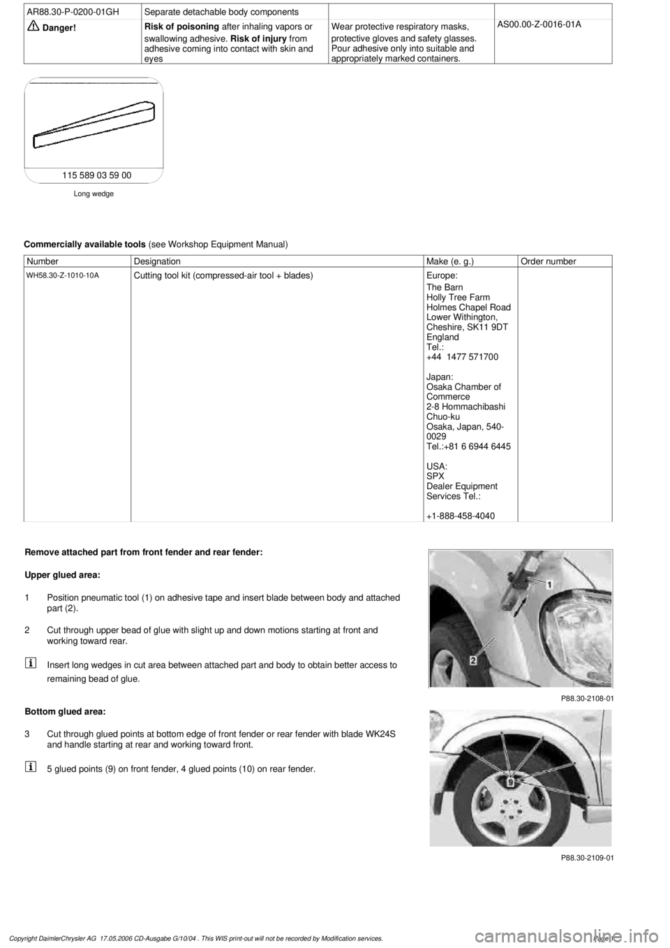
Remove attached part from front fender and rear fender:
Upper glued area:
1
Position pneumatic tool (1) on adhesive tape and insert blade between body and attached
part (2).
2
Cut through upper bead of glue with slight up and down motions starting at front and
working toward rear.
Insert long wedges in cut area between attached part and body to obtain better access to
remaining bead of glue.
P88.30-2109-01
Bottom glued area:
3
Cut through glued points at bottom edge of front fender or rear fender with blade WK24S
and handle starting at rear and working toward front.
5 glued points (9) on front fender, 4 glued points (10) on rear fender.
Copyright DaimlerChrysler AG 17.05.2006 CD-Ausgabe G/10/04 . This WIS print-out will not be recorde
d by Modification services.
Page 1
Page 3961 of 4133

AD54.30-P-5000-02A
Display instruments controlled via CAN
troubleshooting chart IC
The following display instruments or indicator lamps/ malfunction
indicator lamps receive their information from the traction system
control module (N47) via CAN data buses (an appropriate message
appears in the display on vehicles with multi-function display):
D
Total mileage recorder, trip odometer
D
Electronic speedometer
D
Low brake fluid level/parking brake indicator lamp (except model 163
parking brake indicator lamp only via CAN)
D
Brake pad wear indicator lamp
D
ABS MIL
D
ETS, ASR, ESP indicator lamp
D
ETS, ASR, ESP malfunction indicator lamp
Model 163 only:
The
"Low-Range"
indicator lamp receives its information from the
transfer case control module (N78) via CAN data buses.
The
"Fog lamps"
indicator lamp (only model 163 except
I
) receives
its information from the All-activity module (AAM, N10) via CAN data
buses.
Model 168 only:
The
" Gear indicator "
indicator lamp receives its information from the
gear recognition module (A61) or from automatic clutch control module
(N15/4) via CAN data buses.
The following display instruments or indicator lamps/
malfunction indicator lamps receive their information from the
injection system control module (N3) via CAN data buses (an
appropriate message appears in the display on vehicles with
multi-function display):
D
Tachometer
D
Low engine oil level lamp
D
Engine coolant temperature
D
Preglow indicator lamp (diesel only)
D
Vehicle speed warning
D
Vehicle speed limit warning
D
Severe leak warning (
I
only), the fuel reserve indicator lamp
(A1e4) flashes
D
Active Service System (ASSYST):
D
Oil condition
D
Oil level
D
Oil temperature
D
Mass volumetric efficiency (load moment)
D
Engine speed, engine coolant temperature
Copyright DaimlerChrysler AG 05.06.2006 CD-Ausgabe G/10/04 . This WIS print-out will not be recorde
d by Modification services.
Page 1
Page 3965 of 4133

2
Personal Communications Sector
600 North U.S. Highway 45
Libertyville, Illinois 60048
1-800-331-6456 (United States)
1-888-390-6456 (TTY/TDD United States)
1-800-461-4575 (Canada)
www.motorola.com (United States)
www.motorola.ca (Canada)
MOTOROLA, the Stylized M Logo and all other trademarks indicated as such herein are trademarks of Motorola, Inc. ® Reg. U.S. Pat. & Tm. Off. All
other product or service names are the property of their respective owners.
© 2001 Motorola, Inc. All rights reserved. Printed in the U.S.A.
SS S S
oo o o
ff f f
tt t t
ww w w
aa a a
rr r r
ee e e
CC C C
oo o o
pp p p
yy y y
rr r r
iii i
gg g g
hh h h
tt t t
NN N N
oo o o
tt t t
iii i
cc c c
ee e e
The Motorola products described in this manual may include copyrighted Motorola and third party software stored in semiconductor memories or
other media. Laws in the United States and other countries preserve for Motorola and third party software providers certain exclusive rights for
copyrighted software, such as the exclusive rights to distribute or reproduce the copyrighted software. Accordingly, any copyrighted software
contained in the Motorola products may not be modified, reverse-engineered, distributed, or reproduced in any manner to the extent allowed by
law. Furthermore, the purchase of the Motorola products shall not be deemed to grant either directly or by implication, estoppel, or otherwise,
any license under the copyrights, patents, or patent applications of Motorola or any third party software provider, except for the normal, non-
exclusive, royalty-free license to use that arises by operation of law in the sale of a product.
Manual number: 6809435A59-O
Page 3969 of 4133

6
Notes:
• Your phone plays a confirmation beep when docked. Wait for this beep before undocking.
• While in Vehicular Mode, the phone operates on the vehicle’s integrated cellular antenna.
CC C C
aa a a
uu u u
tt t t
iii i
oo o o
nn n n
::: :
Mercedes-Benz recommends keeping the phone docked in the cradle while operating the vehicle. If you
must use the handset for privacy operation, stop the vehicle prior to removing the phone from the cradle.
Installing the Special Battery Insert
The V60 cradle is supplied with a special insert to make it easier to align the phone with the cradle’s embedded connector
when you use certain batteries.
YY Y Y
oo o o
uu u u
ss s s
hh h h
oo o o
uu u u
lll l
dd d d
oo o o
nn n n
lll l
yy y y
iii i
nn n n
ss s s
tt t t
aa a a
lll l
lll l
tt t t
hh h h
iii i
ss s s
iii i
nn n n
ss s s
ee e e
rr r r
tt t t
iii i
ff f f
yy y y
oo o o
uu u u
aa a a
rr r r
ee e e
uu u u
ss s s
iii i
nn n n
gg g g
tt t t
hh h h
ee e e
ss s s
lll l
iii i
mm m m
oo o o
rr r r
hh h h
iii i
gg g g
hh h h
pp p p
ee e e
rr r r
ff f f
oo o o
rr r r
mm m m
aa a a
nn n n
cc c c
ee e e
bb b b
aa a a
tt t t
tt t t
ee e e
rr r r
yy y y
... .
The slim battery is supplied as a standard component in the CDMA V60 kit, while the high performance battery is standard
in the TDMA V60 kit. You should remove the insert when using the optional extra capacity battery.
To install the insert:
44 4 4
Pivot the cradle down to securely latch it.
NN N N
oo o o
tt t t
ee e e
::: :
The cradle should never be placed into the holder with the phone’s flip open.
CC C C
lll l
oo o o
ss s s
ee e e
tt t t
hh h h
ee e e
ff f f
lll l
iii i
pp p p
bb b b
ee e e
ff f f
oo o o
rr r r
ee e e
ss s s
ee e e
cc c c
uu u u
rr r r
iii i
nn n n
gg g g
tt t t
hh h h
ee e e
cc c c
rr r r
aa a a
dd d d
lll l
ee e e
iii i
nn n n
tt t t
hh h h
ee e e
hh h h
oo o o
lll l
dd d d
ee e e
rr r r
in order to prevent damage to the phone when the console cover is closed.
Step
11 1 1
Align the four tabs on the side of the insert with the corresponding slots in the cradle.
22 2 2
Gently push the insert into the slots until it snaps into place.
If you are using the slim battery, the side marked “FOR USE WITH SLIM BATTERY” should face up.
If you are using the high performance battery, the side marked “FOR USE WITH HIGH PERFORMANCE BATTERY” should face up.
33 3 3
If you plan to use the extra capacity battery with your phone, remove the insert by gently prying it out with a small
flat screwdriver, exercising care not to mar the side walls of the cradle.
Step