1997 MERCEDES-BENZ ML500 ESP
[x] Cancel search: ESPPage 3482 of 4133

GF54.30-P-3003A
Indicator/warning messages triggered via CAN data buses, function
24.10.96
MODEL
129, 140 as of 1.6.96,
163, 168, 170,
202 as of 1.8.96,
208 up to 31.7.99,
210 as of 1.6.96 up to 30.6.99
Indicator and warning displays triggered via CAN
Low brake fluid level/parking brake indicator lamp (A1e7)
The parking brake signal comes from the traction system
control module.
The brake fluid signal comes directly from the switch (S11)
(except model 163).
Brake pad wear indicator lamp (A1e6)
The parking brake signal comes from the traction system
control module (N47)
Low engine oil level indicator lamp (A1e12)
The oil level signal comes from the injection system control
module (N3).
For vehicles with ASSYST, also refer to document: ASSYST
engine oil monitoring.
Preglow indicator lamp (A1e16)
The signal comes directly from the injection system control
module (N3).
Coolant level and temperature warning lamp (A1e11) model 168
only as of 9.99
The coolant temperature signal comes from the injection
system control module (N3)
-----------------------------------------------------------------------------------------
ABS MIL (A1e17)
The parking brake signal comes from the traction system
control module (N47).
"CHECK ENGINE" MIL (A1e26),
I
only
The signal comes from the injection system control module (N3)
ETS (A1e35) or ASR (A1e22) or ESP (A1e42) MIL
Lamp illuminated if there is a fault in the respective system.
The signal comes from the traction system control module
(N47).
ETS (A1e36) or ASR (A1e21) or ESP (A1e41) warning lamp
The lamp indicates that the respective system is active.
The signal comes from the traction system control module
(N47).
-----------------------------------------------------------------------------------------
Severe leak warning (
I
as of 97 only)
The fuel reserve indicator lamp (A1e4) flashes. The signal
comes from the injection system control module (N3).
The warning takes place at the earliest 30 minutes after cold
start with the engine idling and the vehicle stationary.
Also refer to document: Purge system with leak test, function
Fog lamps indicator lamp (A1e57), model 163 only except
I
)
The signal comes from the All-activity module (AAM, N10)
"LOW RANGE" indicator lamp (A1e53), model 163 only
The signal comes from the transfer case control module (N78)
Active service system (ASSYST)
Engines 112, 113, 611 (engines with oil
sensor)
GF00.20-P-2009A
Engine oil monitoring, function
Model 210 as of 01.03.97 with engine M111,
OM602, OM604, OM605 and OM606
As of 06.97 models 129, 140, 170, 202 except
engines 112, 113, 611
(Valid for engines with low oil level switch).
GF00.20-P-2009B
Displaying coolant temperature, function
Model 168 as of 9.99
GF54.30-P-3020GC
Purge system with leak test, function
GF47.30-P-3016L
Bus systems, overall function
GF54.00-P-0004A
Copyright DaimlerChrysler AG 04.06.2006 CD-Ausgabe G/10/04 . This WIS print-out will not be recorde
d by Modification services.
Page 1
Page 3484 of 4133

AH40.10-P-9411-01A
Information on tires/rims
Model 124, 129, 140, 163, 168, 169,
170, 171, 199, 201, 202, 203, 208, 209,
210, 211, 215, 219, 220, 230, 240, 414,
450, 452,
639
Tires
D
For service conversions, the tire/disc wheel specifications and
dimensions should be compared with the entries in the
registration papers.
D
When mounting tires, the tires and rims must be carefully
matched in order to guarantee the concentricity of the wheel.
Identification of matching points on:
- Tires with a colored dot on the outside of the tire,
- Sheet steel disk wheel by a colored dot or punch mark on the
outside of the wheel,
- Perform this operation at the valve stem hole on light-alloy
disk wheels
With an additional paint spot or punch mark in the rim base
for the 140 Model Series.
D
Always replace the rubber valve.
-----------------------------------------------------------------------------------------
D
Damaged and defective tires must always be replaced. The
repair methods employed in the tire trade are not approved by
Mercedes-Benz. Small nicks (<0.8mm) on the tire's sidewall do
not usually pose a cause for concern, and continued use of
such tires is approved
D When replacing just one tire, install it on the front of the vehicle.
This does not apply to vehicles with different tires of varying
specifications on the front and rear wheels.
D
Only use tires listed in the valid Service Information bulletins
and repair instructions.
D
If the permissible maximum speed of an M+S tire is below the
maximum speed of the vehicle, an appropriate adhesive plate
must be attached in the driver's field of view.
-----------------------------------------------------------------------------------------
D
Tires permissible for higher speeds may be used.
D
Always fit all rims with tires of the same design, make and
version.
-----------------------------------------------------------------------------------------
D
Run in new tires for approx. 100 km at moderate speed.
D
Handed tires must be installed according to the arrow on the
side wall of the tire.
D
Tires are subject to an aging process with negative effects on
the properties of the tire. In order to ensure optimum
effectiveness in winter, M+S tires should not be used for longer
than 3 years.
-----------------------------------------------------------------------------------------
Tire pressure
(For specified values see tire pressure table in the fuel filler flap, on
the Vaneo BM 414 see B-pillar on the passenger side).
Too low tire pressure increases the rolling resistance and increases
the flexing energy of the tire. This causes the critical temperature limit
to be exceeded (carcass detachment) and destroys the tire. Respond
to loss of tire pressure by determining the source and replacing the
tire as indicated.
Cleaning
Using a spray wand with high-pressure nozzles to clean the wheel
can lead to tire damage. Such damage occurs especially on the tire
side walls. The following should be observed when using flat jet
nozzles:
D
Maintain a minimum distance of 300 mm
D
Do not direct the water jet at a single point on the surface of the
tire for any length of time.
-----------------------------------------------------------------------------------------
Mounting in bearings
Before putting into storage, clean tires thoroughly and check for
damage and adequate tread depth. Mark the position and running
direction of the tires with chalk. Do not store tires outdoors. Under the
influence of sunlight, heat, moving air and ozone the rubber looses
elasticity and strength, ages more quickly and becomes cracked.
Storage areas should be dry, cool and dark. Avoid drafts by keeping
doors and windows closed as much as possible. Do not bring tires
into contact with gasoline, oil or other greases as they dissolve the
rubber.
Disposal
Collection, storage and disposal should be performed in accordance
with the legal requirements and the company's own regulations.
-----------------------------------------------------------------------------------------
Copyright DaimlerChrysler AG 06.07.2006 CD-Ausgabe G/10/04 . This WIS print-out will not be recorde
d by Modification services.
Page 1
Page 3489 of 4133
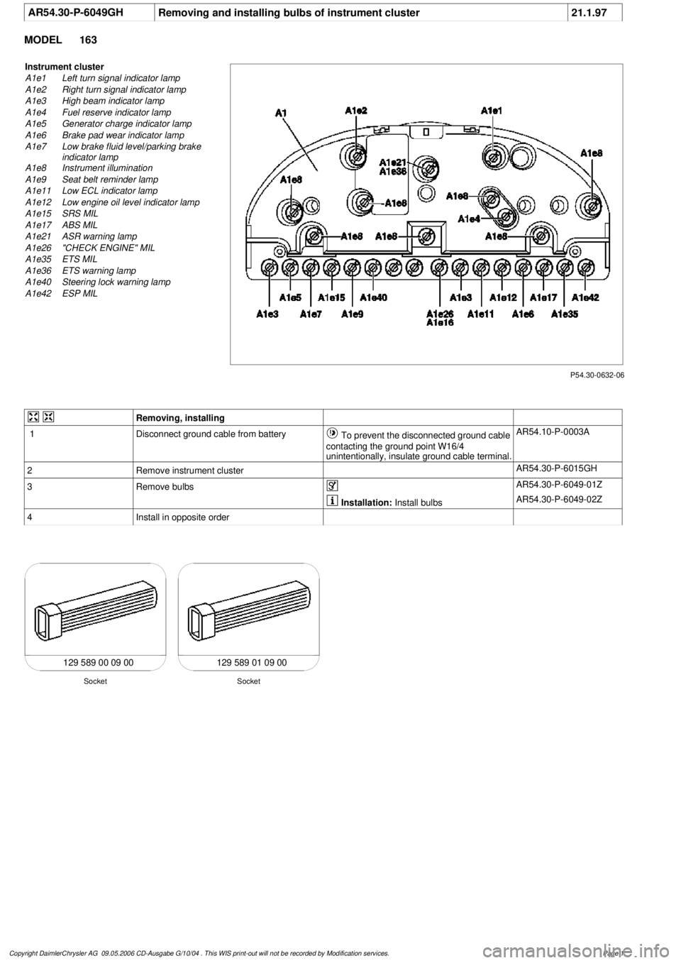
AR54.30-P-6049GH
Removing and installing bulbs of instrument cluster
21.1.97
MODEL
163
P54.30-0632-06
Instrument cluster
A1e1
Left turn signal indicator lamp
A1e2
Right turn signal indicator lamp
A1e3
High beam indicator lamp
A1e4
Fuel reserve indicator lamp
A1e5
Generator charge indicator lamp
A1e6
Brake pad wear indicator lamp
A1e7
Low brake fluid level/parking brake
indicator lamp
A1e8
Instrument illumination
A1e9
Seat belt reminder lamp
A1e11
Low ECL indicator lamp
A1e12
Low engine oil level indicator lamp
A1e15
SRS MIL
A1e17
ABS MIL
A1e21
ASR warning lamp
A1e26
"CHECK ENGINE" MIL
A1e35
ETS MIL
A1e36
ETS warning lamp
A1e40
Steering lock warning lamp
A1e42
ESP MIL
Removing, installing
1
Disconnect ground cable from battery
To prevent the disconnected ground cable
contacting the ground point W16/4
unintentionally, insulate ground cable terminal.
AR54.10-P-0003A
2
Remove instrument cluster
AR54.30-P-6015GH
3
Remove bulbs
AR54.30-P-6049-01Z
Installation:
Install bulbs
AR54.30-P-6049-02Z
4
Install in opposite order
129 589 00 09 00 129 589 01 09 00
Socket
Socket
Copyright DaimlerChrysler AG 09.05.2006 CD-Ausgabe G/10/04 . This WIS print-out will not be recorde
d by Modification services.
Page 1
Page 3496 of 4133

AD54.30-P-5000GH
Instrument cluster (IC) diagnosis troubleshooting
10.4.97
MODEL
163
Connection and use of test equipment
AD00.00-P-1000AZ
Instrument cluster diagnosis, previous
knowledge
AD54.30-P-2000GH
Explanatory notes on diagnosis
troubleshooting chart IC
AD54.30-P-5000-01GH
Display instruments controlled via CAN
troubleshooting chart IC
AD54.30-P-5000-02A
Display instruments controlled directly,
troubleshooting chart IC
AD54.30-P-5000-03A
Troubleshooting
Complaint
Possible cause
Notes
Remedy/Test step
Instrument cluster (A1) completely inoperative
Voltage supply, instrument cluster (A1)
AD54.30-P-6000-01GH
Malfunction indicator lamps or indicator lamps
inoperative
Voltage supply, instrument cluster (A1)
AD54.30-P-6000-01GH
HHT and instrument cluster cannot
communicate
Cables, instrument cluster (A1)
AD54.30-P-6000-02GH
Low brake fluid level/parking brake indicator
lamp, brake pad wear indicator lamp, ABS
MIL, malfunction indicator lamp (ETS, ASR,
ESP) come on together and speedometer
remains on lower stop.
Traction system control module (N47)
AD42.35-P-1001BZ
RPM counter, engine coolant gauge remain
on the lower stop and the low engine oil level
indicator lamp comes on.
Injection system control module (N3)
AD07.61-P-1000AZ
Low brake fluid level/parking brake indicator
lamp, brake pad wear indicator lamp, low
engine oil level indicator lamp, ABS MIL,
malfunction indicator lamp (ETS, ASR, ESP)
come on together and RPM counter, engine
coolant gauge and speedometer remain on
lower stop.
CAN faulty
AD54.30-P-6000-04GH
AD54.30-P-6000-05GH
Steering lock warning lamp (A1e40) is
continuously illuminated or is inoperative.
Cables,
steering lock switch (S97/1)
AD54.30-P-6000-06GH
Coolant level indicator disrupted
Cables,
Coolant level indicator electronic switch (S41)
Model 163 as of 3.98
AD54.30-P-6000-42GH
Copyright DaimlerChrysler AG 05.06.2006 CD-Ausgabe G/10/04 . This WIS print-out will not be recorde
d by Modification services.
Page 1
Page 3519 of 4133
1998-2005 ACCESSORIES & BODY, CAB
Interior Equipment - 163 Chassis
GENERAL INFORMATION
GENERAL NOTES: PASSENGER CARS: INTERIOR EQUIPMENT - AH68.00-Z-9999AZ
MODEL all
NOTES AND LIST OF COMPATIBLE GARAGE DOOR DRIVES FOR GARAGE DOOR OPENER - AH68.05-P-0001-01A
All models with code 231 Garage door opener or with code YF9 Garage door opener
Compatibility, garage door drive to garage door opener
If the garage door drive is not compatible with the garage door opener, a universal receiver (Fix Kit receiver)
can be installed in the garage for modulating the radio signal.
The corresponding compatibility list can be found on the Internet site
http://www.eurohomelink.com
in chapter "HomeLink compatibility".
Additional information on universal receivers is given at the Internet address above and can also be ordered
there.
BASIC KNOWLEDGE
GARAGE DOOR OPENER, FUNCTION - GF68.05-P-0001A
MODEL 129, 202 as of 1.6.98, 203, 208, 210 as of 1.6.98, 215, 220, 230 with CODE (231a) Garage door
opener
MODEL 163 as of 1.9.01, 170 as of 1.6.98
Notes on replacing trim strips in
vehicle interiorMODEL 240AH68.00-P-
0002-01H
Notes and list of compatible garage
door drives for garage door openerMODEL all with CODE (231) Garage door
opener with CODE (YF9) Garage door
openerAH68.05-P-
0001-01A
Notes on operating drawerMODEL 203.0AH68.30-P-
0001-01A
Notes on carrying out repair work in
the vehicle interiorMODEL 240AH68.00-P-
0001-01H
2001 Mercedes-Benz ML320
1998-2005 ACCESSORIES & BODY, CAB Interior Equipment - 163 Chassis
2001 Mercedes-Benz ML320
1998-2005 ACCESSORIES & BODY, CAB Interior Equipment - 163 Chassis
me
Saturday, October 02, 2010 3:35:21 PMPage 1 © 2006 Mitchell Repair Information Company, LLC.
me
Saturday, October 02, 2010 3:35:25 PMPage 1 © 2006 Mitchell Repair Information Company, LLC.
Page 3527 of 4133
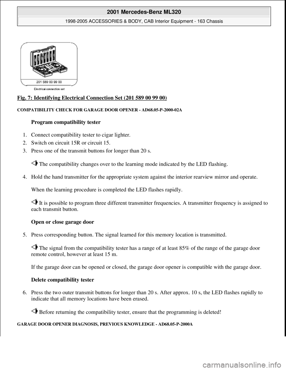
Fig. 7: Identifying Electrical Connection Set (201 589 00 99 00)
COMPATIBILITY CHECK FOR GARAGE DOOR OPENER - AD68.05-P-2000-02A
Program compatibility tester
1. Connect compatibility tester to cigar lighter.
2. Switch on circuit 15R or circuit 15.
3. Press one of the transmit buttons for longer than 20 s.
The compatibility changes over to the learning mode indicated by the LED flashing.
4. Hold the hand transmitter for the appropriate system against the interior rearview mirror and operate.
When the learning procedure is completed the LED flashes rapidly.
It is possible to program three different transmitter frequencies. A transmitter frequency is assigned to
each transmit button.
Open or close garage door
5. Press corresponding button. The signal learned for this memory location is transmitted.
The signal from the compatibility tester has a range of at least 85% of the range of the garage door
remote control, however at least 15 m.
If the garage door can be opened or closed, the garage door opener is compatible with the garage door.
Delete compatibility tester
6. Press the two outer transmit buttons for longer than 20 s. After approx. 10 s, the LED flashes rapidly to
indicate that all memory locations have been erased.
Before returning the compatibility tester, ensure that the programming is deleted!
GARAGE DOOR OPENER DIAGNOSIS, PREVIOUS KNOWLEDGE - AD68.05-P-2000A
2001 Mercedes-Benz ML320
1998-2005 ACCESSORIES & BODY, CAB Interior Equipment - 163 Chassis
me
Saturday, October 02, 2010 3:35:21 PMPage 9 © 2006 Mitchell Repair Information Company, LLC.
Page 3562 of 4133
Instrument panel
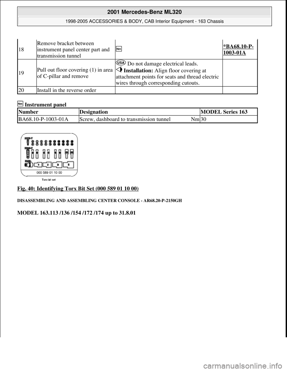
Fig. 40: Identifying Torx Bit Set (000 589 01 10 00)
DISASSEMBLING AND ASSEMBLING CENTER CONSOLE - AR68.20-P-2150GH
MODEL 163.113 /136 /154 /172 /174 up to 31.8.01
18
Remove bracket between
instrument panel center part and
transmission tunnel
*BA68.10-P-
1003-01A
19Pull out floor covering (1) in area
of C-pillar and remove
Do not damage electrical leads.
Installation: Align floor covering at
attachment points for seats and thread electric
wires through corresponding cutouts.
20Install in the reverse order
NumberDesignationMODEL Series 163
BA68.10-P-1003-01AScrew, dashboard to transmission tunnelNm30
2001 Mercedes-Benz ML320
1998-2005 ACCESSORIES & BODY, CAB Interior Equipment - 163 Chassis
me
Saturday, October 02, 2010 3:35:22 PMPage 44 © 2006 Mitchell Repair Information Company, LLC.
Page 3621 of 4133
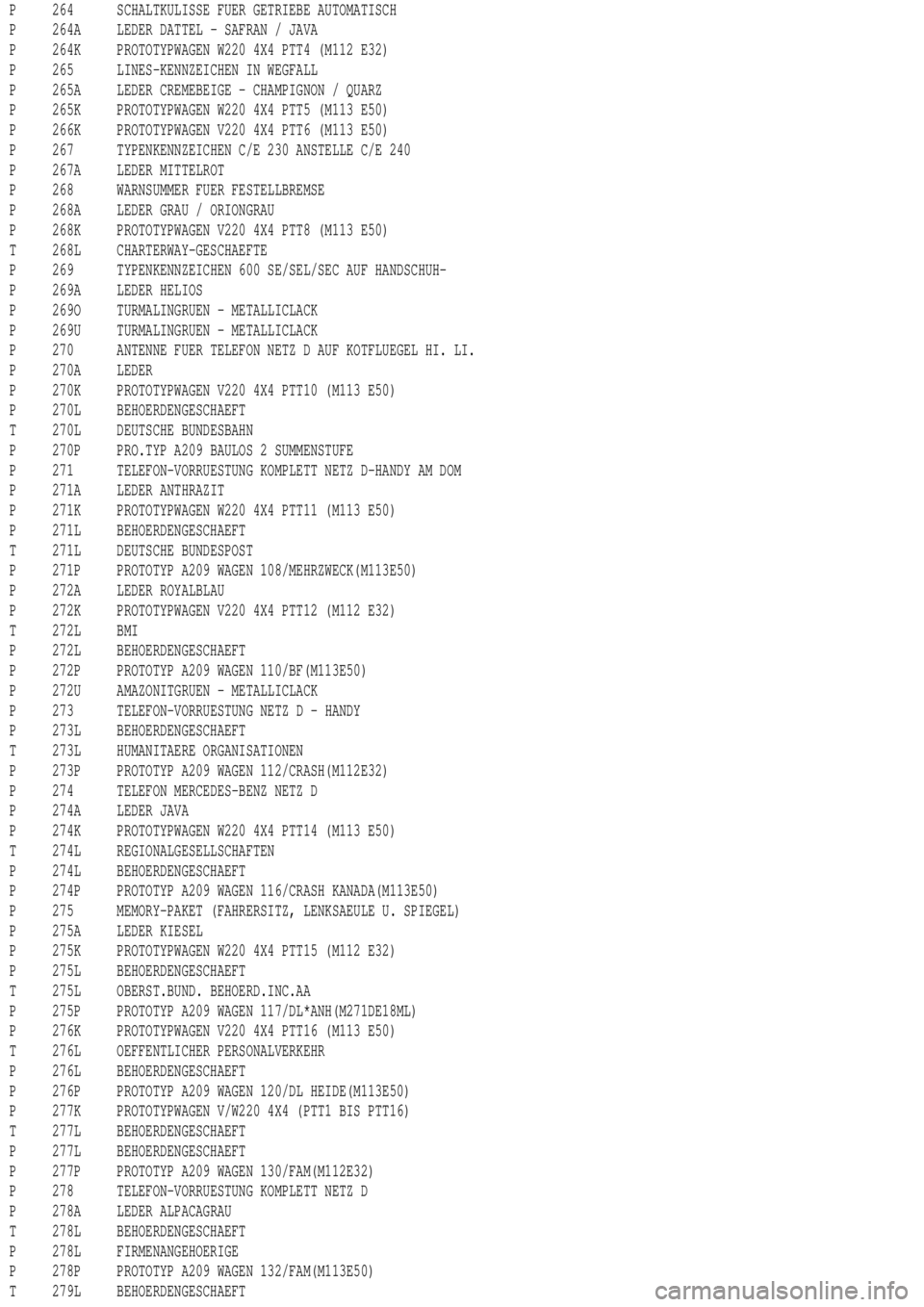
P 264 SCHALTKULISSE FUER GETRIEBE AUTOMATISCH
P 264A LEDER DATTEL - SAFRAN / JAVA
P 264K PROTOTYPWAGEN W220 4X4 PTT4 (M112 E32)
P 265 LINES-KENNZEICHEN IN WEGFALL
P 265A LEDER CREMEBEIGE - CHAMPIGNON / QUARZ
P 265K PROTOTYPWAGEN W220 4X4 PTT5 (M113 E50)
P 266K PROTOTYPWAGEN V220 4X4 PTT6 (M113 E50)
P 267 TYPENKENNZEICHEN C/E 230 ANSTELLE C/E 240
P 267A LEDER MITTELROT
P 268 WARNSUMMER FUER FESTELLBREMSE
P 268A LEDER GRAU / ORIONGRAU
P 268K PROTOTYPWAGEN V220 4X4 PTT8 (M113 E50)
T 268L CHARTERWAY-GESCHAEFTE
P 269 TYPENKENNZEICHEN 600 SE/SEL/SEC AUF HANDSCHUH-
P 269A LEDER HELIOS
P 269O TURMALINGRUEN - METALLICLACK
P 269U TURMALINGRUEN - METALLICLACK
P 270 ANTENNE FUER TELEFON NETZ D AUF KOTFLUEGEL HI. LI.
P 270A LEDER
P 270K PROTOTYPWAGEN V220 4X4 PTT10 (M113 E50)
P 270L BEHOERDENGESCHAEFT
T 270L DEUTSCHE BUNDESBAHN
P 270P PRO.TYP A209 BAULOS 2 SUMMENSTUFE
P 271 TELEFON-VORRUESTUNG KOMPLETT NETZ D-HANDY AM DOM
P 271A LEDER ANTHRAZIT
P 271K PROTOTYPWAGEN W220 4X4 PTT11 (M113 E50)
P 271L BEHOERDENGESCHAEFT
T 271L DEUTSCHE BUNDESPOST
P 271P PROTOTYP A209 WAGEN 108/MEHRZWECK(M113E50)
P 272A LEDER ROYALBLAU
P 272K PROTOTYPWAGEN V220 4X4 PTT12 (M112 E32)
T 272L BMI
P 272L BEHOERDENGESCHAEFT
P 272P PROTOTYP A209 WAGEN 110/BF(M113E50)
P 272U AMAZONITGRUEN - METALLICLACK
P 273 TELEFON-VORRUESTUNG NETZ D - HANDY
P 273L BEHOERDENGESCHAEFT
T 273L HUMANITAERE ORGANISATIONEN
P 273P PROTOTYP A209 WAGEN 112/CRASH(M112E32)
P 274 TELEFON MERCEDES-BENZ NETZ D
P 274A LEDER JAVA
P 274K PROTOTYPWAGEN W220 4X4 PTT14 (M113 E50)
T 274L REGIONALGESELLSCHAFTEN
P 274L BEHOERDENGESCHAEFT
P 274P PROTOTYP A209 WAGEN 116/CRASH KANADA(M113E50)
P 275 MEMORY-PAKET (FAHRERSITZ, LENKSAEULE U. SPIEGEL)
P 275A LEDER KIESEL
P 275K PROTOTYPWAGEN W220 4X4 PTT15 (M112 E32)
P 275L BEHOERDENGESCHAEFT
T 275L OBERST.BUND. BEHOERD.INC.AA
P 275P PROTOTYP A209 WAGEN 117/DL*ANH(M271DE18ML)
P 276K PROTOTYPWAGEN V220 4X4 PTT16 (M113 E50)
T 276L OEFFENTLICHER PERSONALVERKEHR
P 276L BEHOERDENGESCHAEFT
P 276P PROTOTYP A209 WAGEN 120/DL HEIDE(M113E50)
P 277K PROTOTYPWAGEN V/W220 4X4 (PTT1 BIS PTT16)
T 277L BEHOERDENGESCHAEFT
P 277L BEHOERDENGESCHAEFT
P 277P PROTOTYP A209 WAGEN 130/FAM(M112E32)
P 278 TELEFON-VORRUESTUNG KOMPLETT NETZ D
P 278A LEDER ALPACAGRAU
T 278L BEHOERDENGESCHAEFT
P 278L FIRMENANGEHOERIGE
P 278P PROTOTYP A209 WAGEN 132/FAM(M113E50)
T 279L BEHOERDENGESCHAEFT