1997 MERCEDES-BENZ ML430 coolant temperature
[x] Cancel search: coolant temperaturePage 3166 of 4133

Scope: With constant ambient temperatures above freezing point.
1.1.3 Commercial vehicle engines (exception, not for engines OM 500, OM 900, OM 457 and OM
460)
99 vol % Water
1 vol % Refining agent (see Sheet 311.0)
Scope: For constant ambient temperatures above freezing point, e.g. in tropical regions, in which it can be
proven that no approved anticorrosion/antifreeze agents and coolant additives according to Sheet 312.0
are available.
Passenger-car engines, which are installed in a commercial vehicle, must always be filled up as for a
passenger-car engine, refer to points 2.1/2.2.
A quick-glance overview of the fields of application for the approved coolant additives and the
prescribed change intervals are available in Section 5. Please note the mixing prohibition for Sheets 325.3
and 326.3!
1.2 Water
1.2.1 Fresh-water regulations/water treatment
Clean, and where possible, not too hard water should be used for processing the coolant. Drinking water
frequently, although not always, complies with the given specifications.
Sea water, brackish water, brine and industrial waters are not suitable. The level of water containing
dissolved substances can vary greatly depending upon its origin (ground, spring, surface water) and it is
of major significance regarding the presence of corrosion.
Water that is too hard is disadvantageous because of the possibility of scaling or sludging occurring. Salt
content, predominantly chloride, greatly promotes corrosion. If in doubt, analyze the water.
Information concerning the water quality of drinking water is available from the local water-plant
authorities or the official water utilities on request.
If there is no available information regarding the quality of the drinking water then distilled or deionized
water should be used.
If the water fails to comply with the approved analysis values, then it is be processed in a suitable
manner, because even excellent anticorrosion/antifreeze agents are greatly impaired in their ability to
protect against corrosion if water quality is poor.
Should it not be possible to soften the water then the water should be brought up to an approved hardness
by an admixture of soft or distilled (deionized) water.
2004 Mercedes-Benz ML350
1998-2005 GENINFO Overall vehicle - 163 Chassis
me
Saturday, October 02, 2010 3:47:57 PMPage 521 © 2006 Mitchell Repair Information Company, LLC.
Page 3168 of 4133

etc. of these coolant specifications also apply. It is imperative that the correct concentration (50/50) is
used in their application and, of course, further dilution is not permitted!
Approval status:
Coolants for all vehicle and engines (Basis 325.0) Sheet 326.0
Coolants for commercial vehicle and industrial engines (Basis 325.2) Sheet 326.2
Coolants for commercial vehicle and industrial engines (Basis 325.3) Sheet 326.3
The regulations for each respective Sheet 325.x are to be transferred correspondingly to Sheet
326.x.
At the time of compiling these regulations it is possible that not all the Sheets 326.x are represented with
approved products.
2.Coolant additives (General information)
Normally, coolant consists of water and anticorrosion/antifreeze agents. The anticorrosion/antifreeze
agents (ethylene glycol with corrosions inhibitors) in the cooling system have to fulfill, among other
things, the following functions:
to provide sufficient corrosion and cavitation protection for all cooling system components
freezing point depression (antifreeze)
increasing boiling point
For corrosion protection purposes the coolant
approx. 50 vol.-% Anticorrosion/antifreeze agents are added if the expected ambient temperatures do not
require an even higher concentration. This concentration (50 vol %) offers frost protection up to approx. -
37°C. A higher concentration is only necessary if the ambient temperatures are even lower.
Even with extremely low ambient temperatures, not more than 55 vol.-% anticorrosion/antifreeze agent
should be used, because at this level the maximum antifreeze protection is reached and a greater
concentration reduces the antifreeze protection again and decreases the heat dissipation (55 vol.-%
corresponds to antifreeze protection down to approx. -45°C).
Should these coolant regulations fail to be observed then corrosion and damage to the cooling
system are inevitable.
The admixture of anticorrosion/antifreeze agent serves to increase the boiling point. By raising the
pressure the boiling temperature can be increased yet further. Both physical relationships are put to use in
modern cooling systems - the maximum coolant temperature is raised, without increasing the danger of
boiling. In keeping with the higher temperature level the cooling performance is also greater. Only
approved products (Sheet 325.0/326.0 or 325.2 or 326.2, 325.3 or 326.3 as well as 312.0 or 311.0)
2004 Mercedes-Benz ML350
1998-2005 GENINFO Overall vehicle - 163 Chassis
me
Saturday, October 02, 2010 3:47:57 PMPage 523 © 2006 Mitchell Repair Information Company, LLC.
Page 3169 of 4133
provide reliable cooling system protection. In special cases (commercial-vehicle engines, no antifreeze
specification) coolant additives can be used that are primarily corrosion protection additives. In this case
item 2.3 is valid.
As an exception, if neither anticorrosion/antifreeze agent conforming to Sheet 325.0 nor coolant additives
without addition of antifreeze conforming to Sheet 312.0 are available, proceed according to point 2.4
(exception: OM 500 and OM 900). The systems described under items 2.2/2.3/2.4 are not compatible
with each other. It is recommended to mix the entire coolant quantity outside the engine.
2.1 Anticorrosion/antifreeze agent for passenger-car engines
Alongside the correct constitution of the cooling water (point 1.2.2), care must be taken to ensure that
only anticorrosion/antifreeze agents as approved for all engines in accordance with Sheet 325.0 are used.
These products serve to guarantee that, in particular, an effective protection against corrosion is provided
for all light-alloy parts in the cooling system and they are also specified for all passenger-car engines.
In order to ensure that the protection against corrosion is effective, the anticorrosion/antifreeze agent must
remain in the cooling system throughout the year - including when in tropical climates - and regardless of
the operating conditions. In countries with high outside temperatures this is also important in terms of
raising the boiling point.
In the event that these regulations are not observed the cooling system may suffer from damage by
corrosion. As a consequence of corrosion deposits there is a danger that ducts in the radiators (engine
overheating) and heat exchangers (poor heat output) get plugged up thus causing damage to the engine.
As a result of the optimizations we have carried out on the system of engine/coolant/cooling system, in
the majority of our newer passenger cars, a replacement of coolant is not necessary until reaching 15
operating years or 250,000 km (whichever comes first). This may not apply to some models; in these
cases the maintenance booklet will stipulate another regulation.
2.2 Anticorrosion/antifreeze agent for commercial-vehicle engines (normal case)
(not: BR 600, BR 100 and BR 200)
The coolant in commercial-vehicle engines is made up of both water and anticorrosion/antifreeze agent
(refer to item 1.1.1) and as such offers ideal protection against corrosion and cavitation.
All the approved products on the Sheets 325.2, 325.3 or 325.0 which are part of the Specifications for
Operating Fluids can be used to select an anticorrosion/antifreeze agent. However, it should be noted that
passenger vehicle engines built into commercial vehicles must be filled like passenger vehicles (e.g. OM
601 in T1), i.e. a product conforming to Sheet 325.0 and 326.0 must be used.
Products that are not listed in Sheets 325.0 and 326.0, or 325.2 and 326.2, or 325.3 and 326.3 are not
approved and are therefore not to be used under any circumstances.
Anticorrosion/antifreeze agents or coolants conforming to Sheet 325.3 or 326.3 may be used for
longer than other products due to their composition. The change interval is set at 5 years (refer to
2004 Mercedes-Benz ML350
1998-2005 GENINFO Overall vehicle - 163 Chassis
me
Saturday, October 02, 2010 3:47:57 PMPage 524 © 2006 Mitchell Repair Information Company, LLC.
Page 3170 of 4133
Overview Section 5). However, it should always be remembered that anticorrosion/antifreeze
a
gents or coolants conforming to Sheet 325.3 and 326.3 must not be mixed with those conforming to
Sheet 325.0 or 326.0 or 325.2 and 326.2.
2.3 Coolant additives for commercial-vehicle en
gines without antifreeze specifications (refer to item
1.1.2) (not: BR 600, BR 100 and BR 200)
In those application cases where no antifreeze is necessary, coolant for commercial-vehicle engines as
under item 1.1.2 can be mixed to suit. It is impossible to cite generalized mixing proportions because the
application concentrations of products included in Sheet 312.0 may be different. If the tolerances exceed
or fall below those given in Sheet 312.0, then appropriate adjustments must be made. The coolant's
boiling point is only insignificantly increased by these additives. The starting-off water underlies the
more stringent regulations as under point 1.2.3. The usage period for this coolant is shorter than usual (see
position 3). If it is necessary to refill, the same product must be used and at the same concentration level.
The blending of different products is not permitted as stated in Sheet 312.0.
2.4 Coolant regulations for commercial vehicle engines (exception, not for engines OM 500, OM
900, OM 457 and OM 460)
In the event that neither an approved anticorrosion/antifreeze agent is available, nor a coolant additive in
accordance with sheet 312.0 and if temperatures do not drop below freezing then it is possible in this
exceptional case to use a coolant refining agent to 1 vol % if it is approved in sheet 311.0 (soluble
corrosion protection oil). This will not raise the boiling point. The starting-off water itself underlies the
more stringent regulations as under point 1.2.3.
The period of usage for this coolant, which may only be used in exceptional circumstances, is shorter than
usual (refer to position 3).
Water that is too hard may impair the emulsion resistance, with the result that the emulsion
breaks down (oil separation) and the engine's water jackets are contaminated.
2.4.1 Applying water refining mixture
When carrying out a new filling (initial filling or filling after a cleansing operation) an emulsion of 1.0-
1.5 vol % should be used. When refilling, an emulsion of 0.5-1.0 vol % should be used. Concentrations
that are too high (>1.5 vol %) do not improve the corrosion protection capability and may exert a negative
influence on seals and hoses.
3.Monitoring coolant operation
It is very important to monitor the coolant constantly if the engine is to run trouble free.
The concentration level should be checked every six months.
The inspection should be conducted with suitable apparatus. If, when monitoring the concentration of the
coolant, it is determined that the concentration of anticorrosion/antifreeze agent has reached 40 vol.% or
less or an antifreeze protection of -28°C is no lon
ger guaranteed, the concentration must be increased to
2004 Mercedes-Benz ML350
1998-2005 GENINFO Overall vehicle - 163 Chassis
me
Saturday, October 02, 2010 3:47:57 PMPage 525 © 2006 Mitchell Repair Information Company, LLC.
Page 3175 of 4133
GENERAL BRAKE FLUID - BB00.40-P-0330-01A
These specifications are valid for the Mercedes-Benz and smart brands.
General
The brake fluid in the brake system and in the hydraulic clutch operating system fulfills hydraulic tasks. Due to
the high heat build-up during braking, these tasks can only be fulfilled by brake fluids which comply with all of
today's technical requirements in terms of their various properties (viscosity-temperature-characteristic, boiling
point, corrosion protection, oxidation resistance, etc.).
The most important properties which a brake fluid must exhibit are:
High boiling point, to ensure that the brake fluid does not form vapor locks at high temperatures. Vapor
locks reduce the operating pressure and thus the braking effect and may ultimately lead to brake failure.
The boiling point should remain as constant as possible throughout the duration of use of the coolant and
not drop under varying atmospheric influences or operating conditions (pressure, temperature), i.e. the
"wet boiling point" should be as high as possible.
Low compressibility, in particular at high temperatures.
The low-temperature characteristic of the fluid - even when at 40°C - must permit operation, i.e.
primarily, the viscosity must not become too high in the cold.
Compatibility with the materials used in the brake units and clutch operating systems, e.g. the rubber
boots or any other seal materials (elastomers) included in the brake components may only swell to a
controlled extent, any shrinkage must be avoided.
Sufficient corrosion protection for all metals present in the brake system.
The brake fluids released for use in MB vehicle models are listed on Sheet 331.0. These brake fluids not only
comply with our requirements, but also those of the US safety specifications FMVSS 116, DOT 4. The released
"DOT 4 plus" brake fluids (internal designation) are more advanced DOT 4 brake fluids with higher wet boiling
point, standard change interval: 2 years. In order to be able to comply with this useful period without any
problem, we strongly advise the use of released products as per Sheet 331.0, during the warranty phase this is a
precondition for any acceptance of customer claims.
The brake fluid listed on Sheet 331.1 "DOT 4 Type 200" is released for special applications in the UNIMOG
range with more stringent thermal requirements. For this type of use, a brake fluid change interval of 1 year
must be adhered to.
Handling brake fluid
Brake fluid based on polyhydric alcohols in oligomer or polymer form and/or their
Esters are hygroscopic and thus absorbs moisture from the air. Water, however, reduces the boiling point of the
brake fluid, whereby the danger of vapor lock formation is present. Therefore it should be noted that brake fluid
is always stored in sealed vessels. Brake fluid that has been stored unsealed can absorb so much moisture in a
few hours that it is rendered unusable.
2004 Mercedes-Benz ML350
1998-2005 GENINFO Overall vehicle - 163 Chassis
me
Saturday, October 02, 2010 3:47:57 PMPage 530 © 2006 Mitchell Repair Information Company, LLC.
Page 3221 of 4133
TESTS.
Normal Ventilation In Regulating Mode
To check normal ventilation in regulating mode, set temperature selector knob to White range (vertical). Set
mode control knob to 4-o'clock position. Ensure A/C button indicator is illuminated. Air will vent from upper
and lower outlets and A/C compressor will engage. Ambient air will flow from center outlet and coolant
circulation pump will operate. If operation is not as specified, perform the following in order:
Check A/C button activation. See A/C BUTTON under ELECTRICAL TESTS.
Check A/C pressure switch. See A/C REFRIGERANT PRESSURE SWITCH under ELECTRICAL
TESTS.
Economy Setting Not In Heating Mode
To check economy setting without heating mode activated, set temperature selector knob to Blue range. Set
mode control knob to the 9-o'clock position. Ensure A/C button indicator is not illuminated. Ambient air will
flow from center outlet and A/C compressor will NOT be engaged. If operation is not as specified, perform the
following:
Check A/C button activation. See A/C BUTTON under ELECTRICAL TESTS.
Economy Setting In Heating Mode
To check economy setting with heating mode activated, set temperature selector knob to Red range. Set mode
control knob to the 4-o'clock position. Ensure A/C button indicator is not illuminated. Heated air will flow from
lower, upper and center outlets and A/C compressor will NOT be engaged. If operation is not as specified,
perform the following:
Check A/C button activation. See A/C BUTTON under ELECTRICAL TESTS.
Recirculation Mode
To check recirculation mode, press fresh/recirculation button. Ensure fresh/recirculation indicator is
illuminated. Set blower speed knob to position No. 4. Blower fan noise will increase noticeably. If operation is
not as specified, check wiring between recirculated air flap element, heater-A/C switch and No. 16 fuse (15-
amp).
ELECTRICAL TESTS
Voltage Supply Circuit Z50/2
1. Connect socket box to A/C push button control unit and wiring harness. See CONNECTING TEST
EQUIPMENT . Turn ignition on, with engine off. Connect voltmeter positive lead to socket box terminal
No. 7 and negative lead to terminal No. 9.
2. Voltage should be 11-14 volts. If voltage is not as specified, check voltage supply circuit Z50/2 between
No. 16 fuse (15-amp) and connected components. See WIRING DIAGRAMS
. Repair as necessary.
2001 Mercedes-Benz ML320
2000-01 MANUAL A/C-HEATER SYSTEMS ML 320, ML 430 & ML 55
me
Saturday, October 02, 2010 3:25:10 PMPage 10 © 2006 Mitchell Repair Information Company, LLC.
Page 3225 of 4133
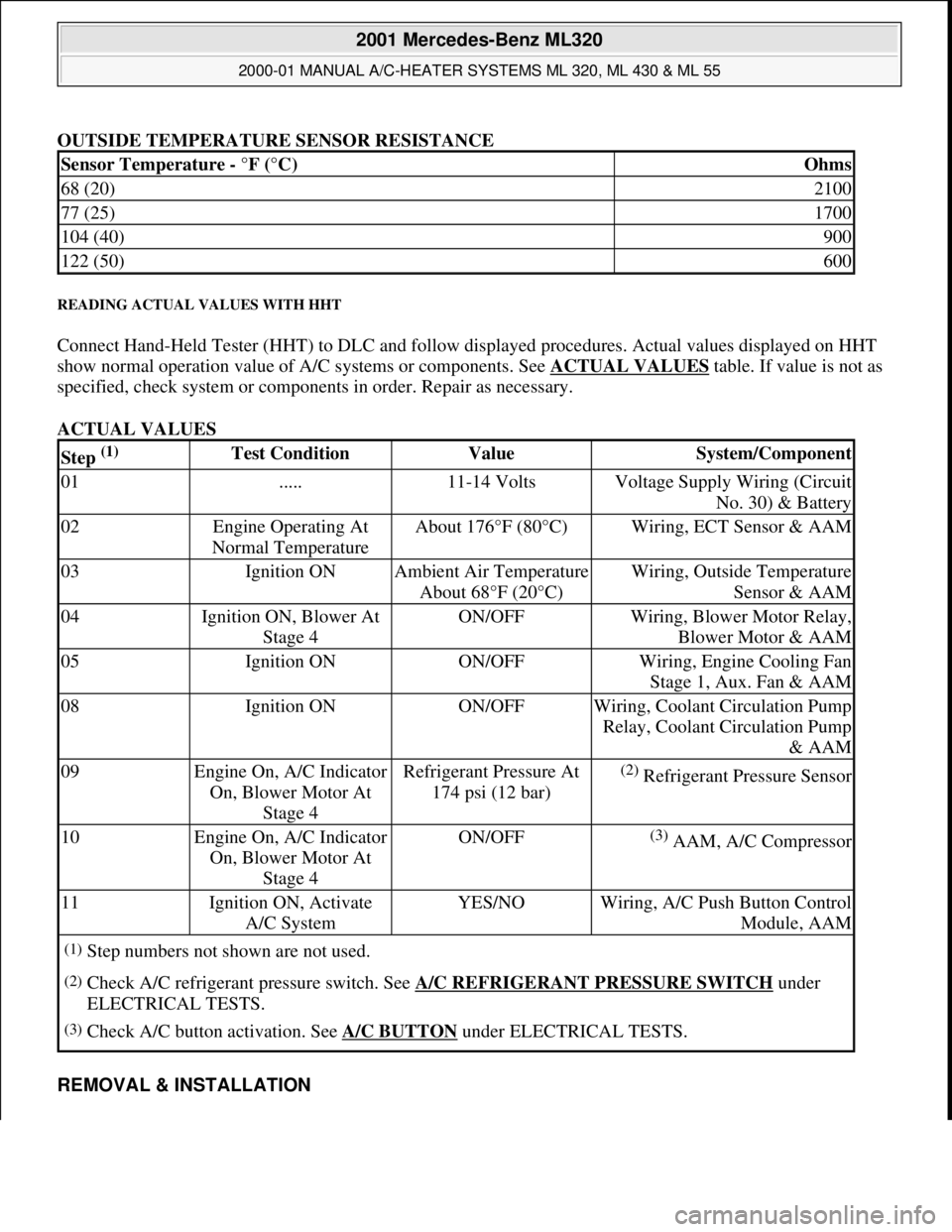
OUTSIDE TEMPERATURE SENSOR RESISTANCE
READING ACTUAL VALUES WITH HHT
Connect Hand-Held Tester (HHT) to DLC and follow displayed procedures. Actual values displayed on HHT
show normal operation value of A/C systems or components. See ACTUAL VALUES
table. If value is not as
specified, check system or components in order. Repair as necessary.
ACTUAL VALUES
REMOVAL & INSTALLATION
Sensor Temperature - °F (°C)Ohms
68 (20)2100
77 (25)1700
104 (40)900
122 (50)600
Step (1) Test ConditionValueSystem/Component
01.....11-14 VoltsVoltage Supply Wiring (Circuit
No. 30) & Battery
02Engine Operating At
Normal TemperatureAbout 176°F (80°C)Wiring, ECT Sensor & AAM
03Ignition ONAmbient Air Temperature
About 68°F (20°C)Wiring, Outside Temperature
Sensor & AAM
04Ignition ON, Blower At
Stage 4ON/OFFWiring, Blower Motor Relay,
Blower Motor & AAM
05Ignition ONON/OFFWiring, Engine Cooling Fan
Stage 1, Aux. Fan & AAM
08Ignition ONON/OFFWiring, Coolant Circulation Pump
Relay, Coolant Circulation Pump
& AAM
09Engine On, A/C Indicator
On, Blower Motor At
Stage 4Refrigerant Pressure At
174 psi (12 bar)(2) Refrigerant Pressure Sensor
10Engine On, A/C Indicator
On, Blower Motor At
Stage 4ON/OFF(3) AAM, A/C Compressor
11Ignition ON, Activate
A/C SystemYES/NOWiring, A/C Push Button Control
Module, AAM
(1)Step numbers not shown are not used.
(2)Check A/C refrigerant pressure switch. See A/C REFRIGERANT PRESSURE SWITCH under
ELECTRICAL TESTS.
(3)Check A/C button activation. See A/C BUTTON under ELECTRICAL TESTS.
2001 Mercedes-Benz ML320
2000-01 MANUAL A/C-HEATER SYSTEMS ML 320, ML 430 & ML 55
me
Saturday, October 02, 2010 3:25:10 PMPage 14 © 2006 Mitchell Repair Information Company, LLC.
Page 3226 of 4133
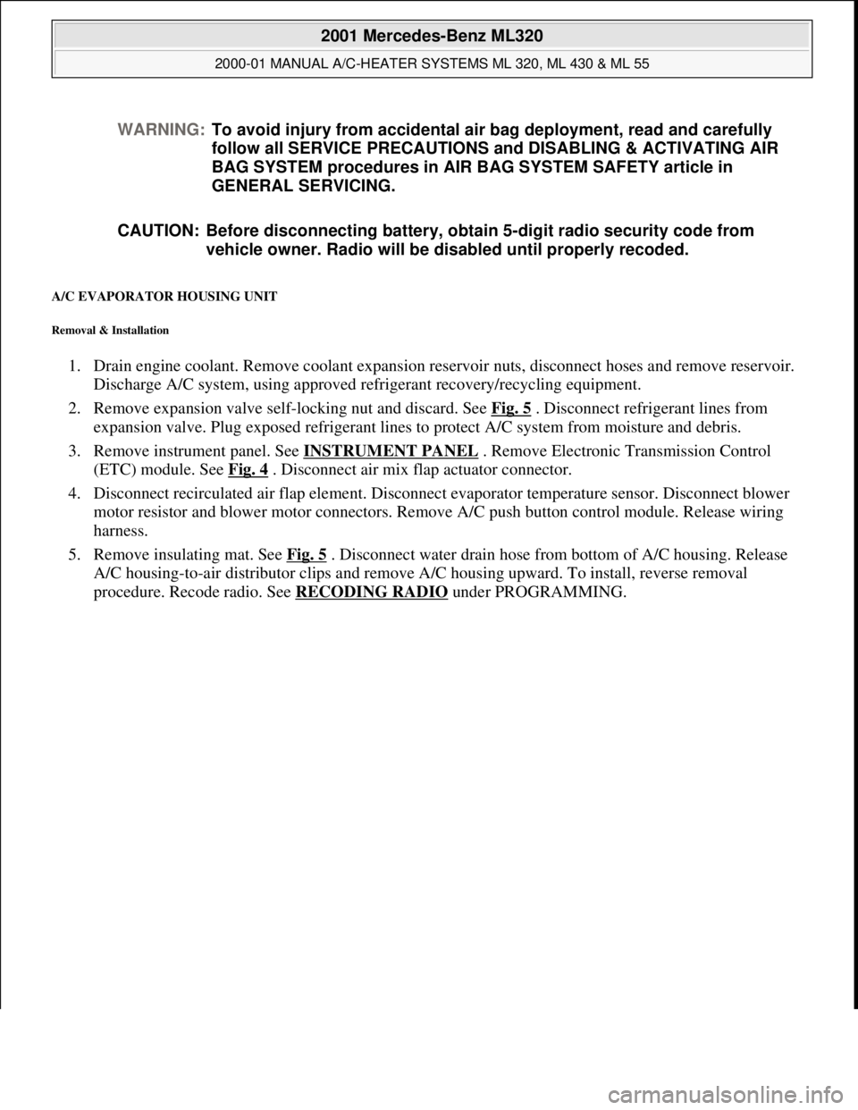
A/C EVAPORATOR HOUSING UNIT
Removal & Installation
1. Drain engine coolant. Remove coolant expansion reservoir nuts, disconnect hoses and remove reservoir.
Discharge A/C system, using approved refrigerant recovery/recycling equipment.
2. Remove expansion valve self-locking nut and discard. See Fig. 5
. Disconnect refrigerant lines from
expansion valve. Plug exposed refrigerant lines to protect A/C system from moisture and debris.
3. Remove instrument panel. See INSTRUMENT PANEL
. Remove Electronic Transmission Control
(ETC) module. See Fig. 4
. Disconnect air mix flap actuator connector.
4. Disconnect recirculated air flap element. Disconnect evaporator temperature sensor. Disconnect blower
motor resistor and blower motor connectors. Remove A/C push button control module. Release wiring
harness.
5. Remove insulating mat. See Fig. 5
. Disconnect water drain hose from bottom of A/C housing. Release
A/C housing-to-air distributor clips and remove A/C housing upward. To install, reverse removal
procedure. Recode radio. See RECODING RADIO
under PROGRAMMING. WARNING:To avoid injury from accidental air bag deployment, read and carefully
follow all SERVICE PRECAUTIONS and DISABLING & ACTIVATING AIR
BAG SYSTEM procedures in AIR BAG SYSTEM SAFETY article in
GENERAL SERVICING.
CAUTION: Before disconnecting battery, obtain 5-digit radio security code from
vehicle owner. Radio will be disabled until properly recoded.
2001 Mercedes-Benz ML320
2000-01 MANUAL A/C-HEATER SYSTEMS ML 320, ML 430 & ML 55
me
Saturday, October 02, 2010 3:25:10 PMPage 15 © 2006 Mitchell Repair Information Company, LLC.