1997 MERCEDES-BENZ ML430 coolant temperature
[x] Cancel search: coolant temperaturePage 3232 of 4133
Fig. 6: Removing Cooling Fans & Condenser
Courtesy of MERCEDES-BENZ OF NORTH AMERICA.
COOLING FANS
Removal & Installation
Remove headlight units. Remove upper frame crossmember, release hood release control cable and remove
crossmember. See Fig. 6
. Remove 2 cooling fans frame bolts on radiator. Disconnect cooling fan connector.
Release outside temperature sensor wiring harness. Pull up on cooling fan and remove. To install, reverse
removal procedure. Ensure cooling fan bottom guides are properly seated in lower mounts.
EVAPORATOR
Removal & Installation
Remove A/C housing unit. See A/C HOUSING UNIT . Remove expansion valve. See Fig. 5 . Discard "O"
rings. Disassemble A/C housing unit. Remove evaporator. Remove evaporator temperature sensor. To install,
reverse removal procedure. Use NEW "O" rings lubricated with refrigerant oil. If installing a new or repair
evaporator, add 1.35 ounces of NEW refrigerant oil to evaporator.
EXPANSION VALVE
Removal & Installation
1. Discharge A/C system, using approved refrigerant recovery/recycling equipment. Without disconnecting
coolant hoses, remove coolant expansion reservoir and set aside. Remove refrigerant line bracket and
loosen clamps. See Fig. 5
. Pull refrigerant lines out of expansion valve.
2. Remove expansion valve self-locking nut and discard. Remove expansion valve. Discard "O" rings. To
install, reverse removal procedure. Use NEW "O" rings lubricated with refrigerant oil. Tighten NEW self-
locking nut to specification. See TORQUE SPECIFICATIONS
.
INSTRUMENT PANEL & INSTRUMENT PANEL CARRIER
Removal & Installation
1. Secure vehicle against rolling. Set transmission selector to "D" position. Obtain radio security code.
Disconnect negative battery cable. Remove driver-side air bag.
2. Place match marks on steering wheel and steering shaft. Remove steering wheel, upper steering column
covers and combination switch. Remove instrument cluster cover frame. Remove one instrument panel
lower section bolt.
3. Remove screws in footwell from left side of instrument panel bottom section. Remove instrument panel
center section. Remove 4 A/C control panel screws and remove control panel. See Fig. 1
. Release pull
cables and disconnect connectors.
4. Remove screws from center section. Remove glove box. Remove screws in footwell from right side of
instrument panel bottom section. Remove entry courtesy lights. Remove end covers and screws.
5. Release 4 "A" clips between instrument panel bottom section and upper section. See Fig. 7
. Release
parkin
g brake release cable from handle. With assistance, remove instrument panel bottom section.
2001 Mercedes-Benz ML320
2000-01 MANUAL A/C-HEATER SYSTEMS ML 320, ML 430 & ML 55
me
Saturday, October 02, 2010 3:25:10 PMPage 21 © 2006 Mitchell Repair Information Company, LLC.
Page 3268 of 4133
Function
Rotating the air distribution switch in the AAC push-button control module (N22) actuates the footwell flap
actuator motor via the AC bus. The footwell flap actuator motor (M2/21) controls the footwell flap, which
adopts the following positions according to requirements.
Switching logic
footwell flap closed = 0%
footwell flap open = 100%
Automatic footwell flap control (Auto button engaged)
The footwell flap is opened depending on the following values
blending air flap setting
Coolant temperature
Evaporator temperature
linear up to 100 % open.
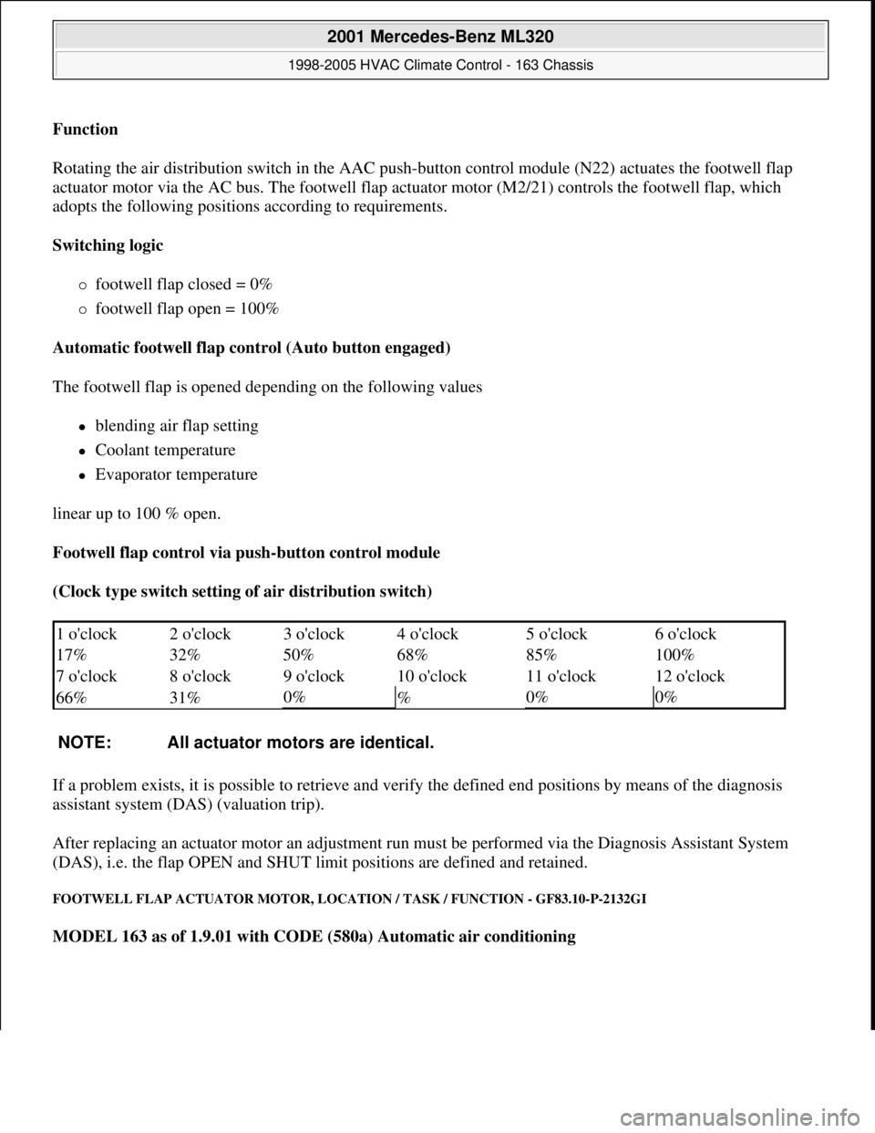
Footwell flap control via push-button control module
(Clock type switch setting of air distribution switch)
If a problem exists, it is possible to retrieve and verify the defined end positions by means of the diagnosis
assistant system (DAS) (valuation trip).
After replacing an actuator motor an adjustment run must be performed via the Diagnosis Assistant System
(DAS), i.e. the flap OPEN and SHUT limit positions are defined and retained.
FOOTWELL FLAP ACTUATOR MOTOR, LOCATION / TASK / FUNCTION - GF83.10-P-2132GI
MODEL 163 as of 1.9.01 with CODE (580a) Automatic air conditioning
1 o'clock 2 o'clock 3 o'clock 4 o'clock 5 o'clock6 o'clock
17% 32% 50% 68% 85%
100%
7 o'clock 8 o'clock 9 o'clock 10 o'clock 11 o'clock
12 o'clock
66% 31%
0%
%0%0%
NOTE: All actuator motors are identical.
2001 Mercedes-Benz ML320
1998-2005 HVAC Climate Control - 163 Chassis
me
Saturday, October 02, 2010 3:23:15 PMPage 24 © 2006 Mitchell Repair Information Company, LLC.
Page 3277 of 4133
BLOWER MOTOR FUNCTION - GF83.10-P-2170-01GI
Function
The AAC push-button control module (N22) passes a control voltage of 0-6 V to the blower regulator (A32n1)
via the AC bus. Depending on the control voltage which is present, this then regulates the blower motor
(A32m1) operating voltage of 0-12 V. This facilitates blower speed control of 0-100 %.
The blower motor actuation (operating voltage) is influenced by the following factors:
Blower power setting manual or AUTO
Operating functions:
Air distribution
AC OFF mode
Residual engine heat mode (actuation limited to 5 V)
Mode status (heating, cooling)
Coolant temperature
Vehicle speed
Fresh air/recirculation flap setting
Flap positions
Terminal 15 (blower ON), starter running (blower OFF)
BLOWER MOTOR LOCATION/TASK/DESIGN/FUNCTION - GF83.10-P-2170GI
MODEL 163 as of 1.9.01 with CODE (580a) Automatic air conditioning
Blower, task
The rear blower motor (M2/1) serves to improve ventilation and cooling
in the rear.
The air that is drawn in by the blower in the evaporator housing is led to
the rear blower motor (M2/1) via air ducts.
The rear blower motor (M2/1) increases the flow of air.
Blower,
function GF83.10-P-
2168-01GI
2001 Mercedes-Benz ML320
1998-2005 HVAC Climate Control - 163 Chassis
me
Saturday, October 02, 2010 3:23:15 PMPage 33 © 2006 Mitchell Repair Information Company, LLC.
Page 3280 of 4133
Function
Rotating the air distribution switch in the AAC push-
button control module (N22) actuates the center outlet flap
actuator motor (M2/22) via the AC bus. The center outlet flap actuator motor (M2/22) controls the center outlet
flap, which adopts the following positions according to requirements.
Switching logic
center outlet flap closed = 0%
center outlet flap open = 100%
Automatic center outlet flap control (Auto button engaged)
The center outlet flap is opened depending on the following values
blending air flap setting
Coolant temperature
Evaporator temperature
linear up to 100 % open.
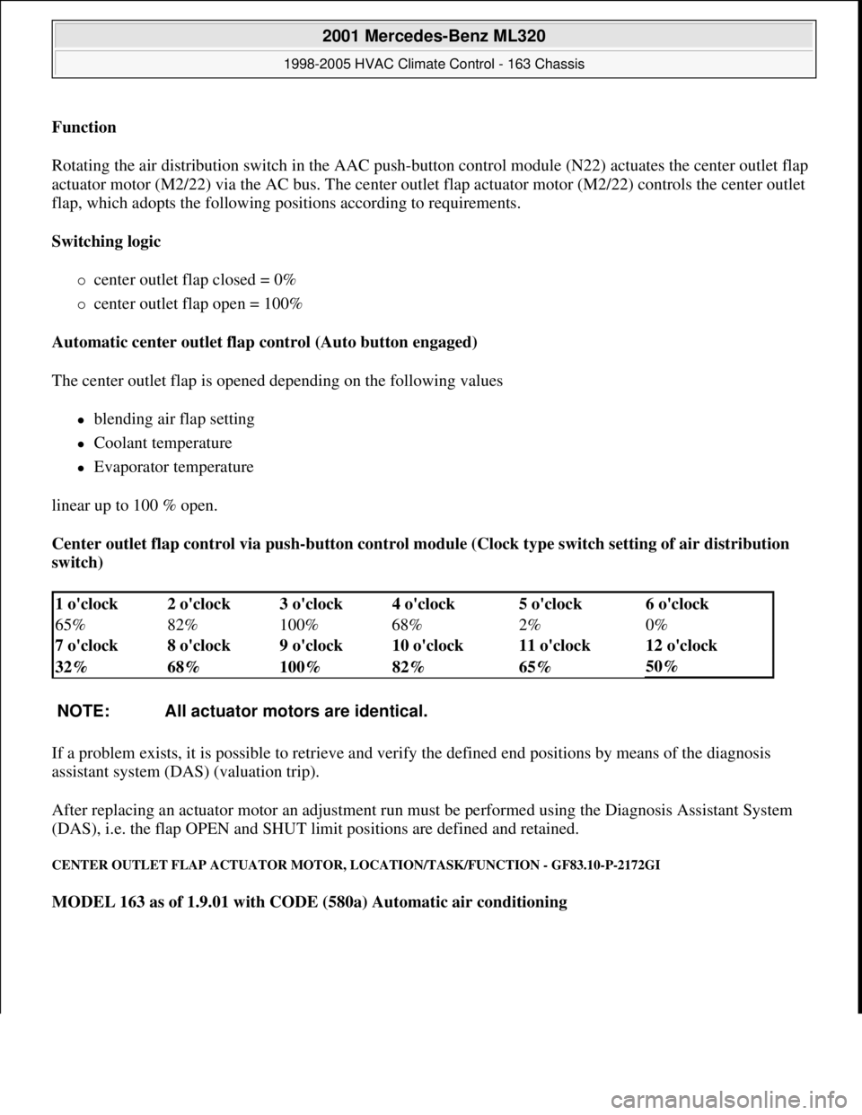
Center outlet flap control via push-button control module (Clock type switch setting of air distribution
switch)
If a problem exists, it is possible to retrieve and verify the defined end positions by means of the diagnosis
assistant system (DAS) (valuation trip).
After replacing an actuator motor an adjustment run must be performed using the Diagnosis Assistant System
(DAS), i.e. the flap OPEN and SHUT limit positions are defined and retained.
CENTER OUTLET FLAP ACTUATOR MOTOR, LOCATION/TASK/FUNCTION - GF83.10-P-2172GI
MODEL 163 as of 1.9.01 with CODE (580a) Automatic air conditioning
1 o'clock 2 o'clock 3 o'clock 4 o'clock 5 o'clock6 o'clock
65% 82% 100% 68% 2%
0%
7 o'clock 8 o'clock 9 o'clock 10 o'clock 11 o'clock
12 o'clock
32% 68% 100% 82% 65%
50%
NOTE: All actuator motors are identical.
2001 Mercedes-Benz ML320
1998-2005 HVAC Climate Control - 163 Chassis
me
Saturday, October 02, 2010 3:23:15 PMPage 36 © 2006 Mitchell Repair Information Company, LLC.
Page 3287 of 4133
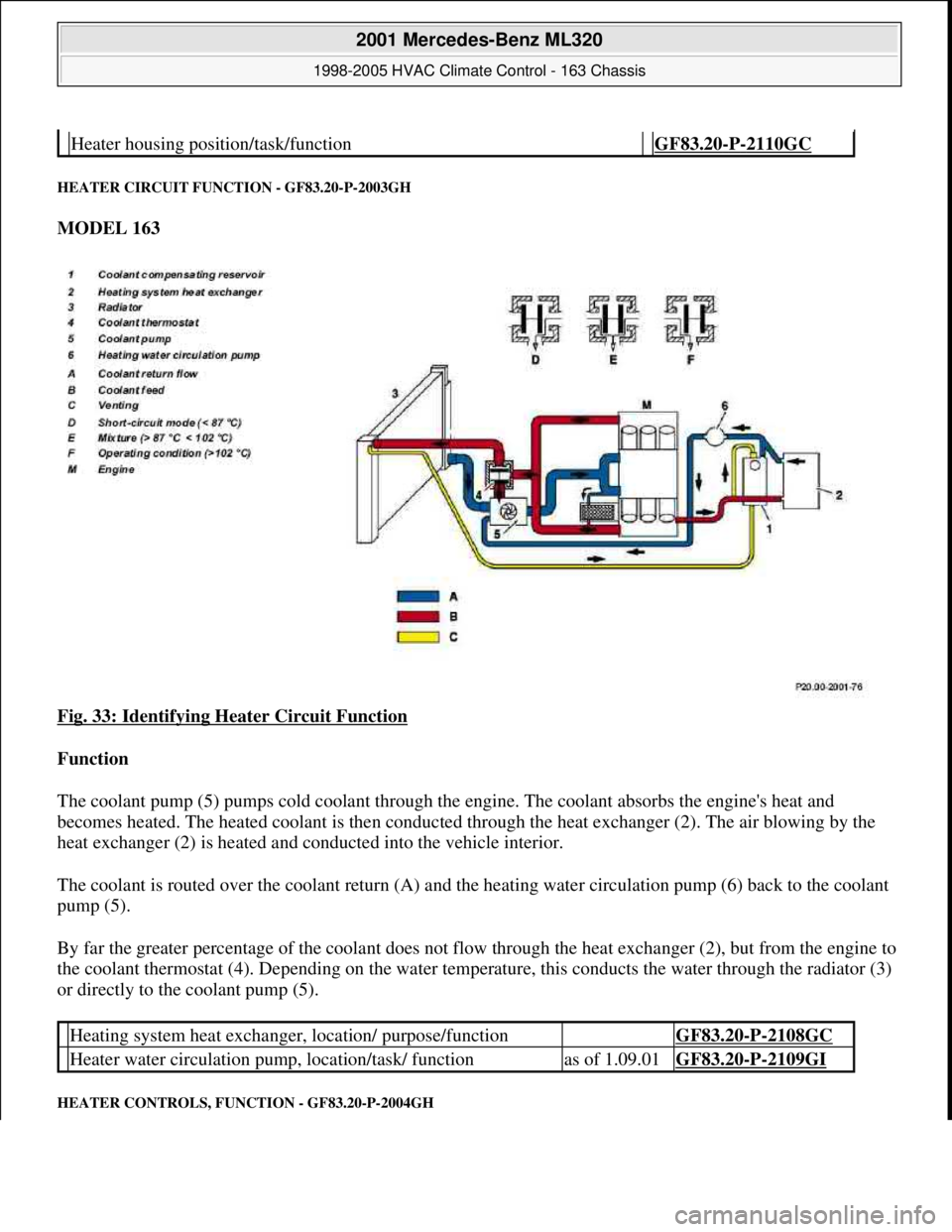
HEATER CIRCUIT FUNCTION - GF83.20-P-2003GH
MODEL 163
Fig. 33: Identifying Heater Circuit Function
Function
The coolant pump (5) pumps cold coolant through the engine. The coolant absorbs the engine's heat and
becomes heated. The heated coolant is then conducted through the heat exchanger (2). The air blowing by the
heat exchanger (2) is heated and conducted into the vehicle interior.
The coolant is routed over the coolant return (A) and the heating water circulation pump (6) back to the coolant
pump (5).
By far the greater percentage of the coolant does not flow through the heat exchanger (2), but from the engine to
the coolant thermostat (4). Depending on the water temperature, this conducts the water through the radiator (3)
or directly to the coolant pump (5).
HEATER CONTROLS, FUNCTION - GF83.20-P-2004GH
Heater housing position/task/function GF83.20-P-2110GC
Heating system heat exchanger, location/ purpose/function GF83.20-P-2108GC
Heater water circulation pump, location/task/ functionas of 1.09.01GF83.20-P-2109GI
2001 Mercedes-Benz ML320
1998-2005 HVAC Climate Control - 163 Chassis
me
Saturday, October 02, 2010 3:23:15 PMPage 43 © 2006 Mitchell Repair Information Company, LLC.
Page 3288 of 4133
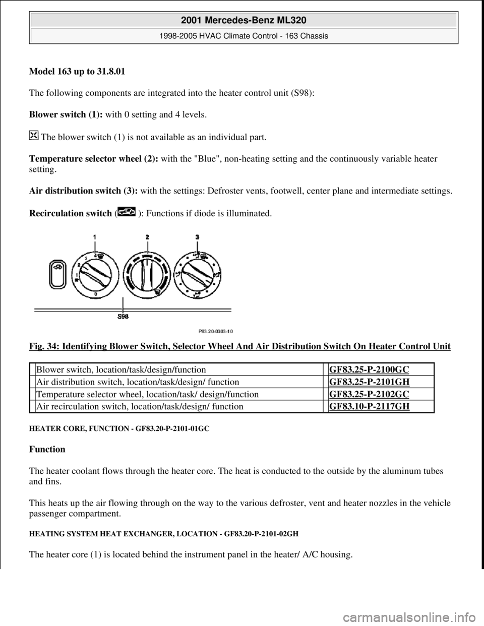
Model 163 up to 31.8.01
The following components are integrated into the heater control unit (S98):
Blower switch (1): with 0 setting and 4 levels.
The blower switch (1) is not available as an individual part.
Temperature selector wheel (2): with the "Blue", non-heating setting and the continuously variable heater
setting.
Air distribution switch (3): with the settings: Defroster vents, footwe ll, center plane and intermediate settings.
Recirculation switch ( ): Functions if diode is illuminated.
Fig. 34: Identifying Blower Switch, Selector Wheel And Air Distribution Switch On Heater Control Unit
HEATER CORE, FUNCTI ON - GF83.20-P-2101-01GC
Function
The heater coolant flows through the heater core. The he at is conducted to the outside by the aluminum tubes
and fins.
This heats up the air flowing through on the way to the vari ous defroster, vent and heater nozzles in the vehicle
passenger compartment.
HEATING SYSTEM HEAT EXCHANGE R, LOCATION - GF83.20-P-2101-02GH
The heater core (1) is located behind the instrument panel in the heater/ A/C housing.
Blower switch, location/task/design/function GF83.25-P-2100GC
Air distribution switch, locat ion/task/design/ function GF83.25-P-2101GH
Temperature selector wheel, location/task/ design/function GF83.25-P-2102GC
Air recirculation switch, loca tion/task/design/ function GF83.10-P-2117GH
2001 Mercedes-Benz ML320
1998-2005 HVAC Climate Control - 163 Chassis
me
Saturday, October 02, 2010 3:23:15 PMPage 44 © 2006 Mitchell Repair Information Company, LLC.
Page 3289 of 4133
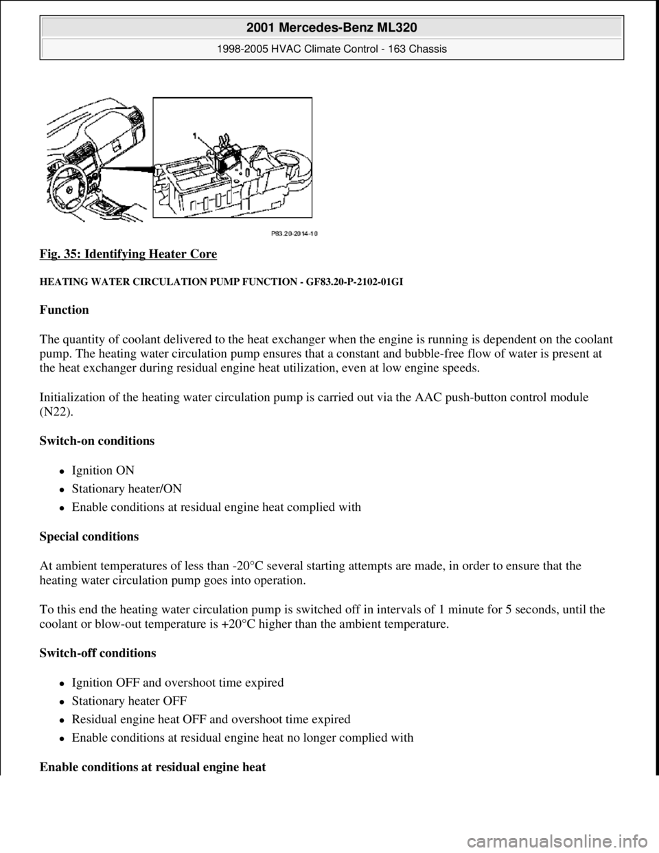
Fig. 35: Identifying Heater Core
HEATING WATER CIRCULATION PUMP FUNCTION - GF83.20-P-2102-01GI
Function
The quantity of coolant delivered to the heat exchanger when the engine is running is dependent on the coolant
pump. The heating water circulation pump ensures that a constant and bubble-free flow of water is present at
the heat exchanger during residual engine heat utilization, even at low engine speeds.
Initialization of the heating water circulation pump is carried out via the AAC push-button control module
(N22).
Switch-on conditions
Ignition ON
Stationary heater/ON
Enable conditions at residual engine heat complied with
Special conditions
At ambient temperatures of less than -20°C several starting attempts are made, in order to ensure that the
heating water circulation pump goes into operation.
To this end the heating water circulation pump is switched off in intervals of 1 minute for 5 seconds, until the
coolant or blow-out temperature is +20°C higher than the ambient temperature.
Switch-off conditions
Ignition OFF and overshoot time expired
Stationary heater OFF
Residual engine heat OFF and overshoot time expired
Enable conditions at residual engine heat no longer complied with
Enable conditions at residual engine heat
2001 Mercedes-Benz ML320
1998-2005 HVAC Climate Control - 163 Chassis
me
Saturday, October 02, 2010 3:23:15 PMPage 45 © 2006 Mitchell Repair Information Company, LLC.
Page 3290 of 4133
The heating water circulation pump runs in any event 1 minute after starting residual engine heat operation. The
overshoot conditions at least will be fulfilled.
Overshoot conditions
Coolant temperature 100°C --> overshoot time 5 minutes
Coolant temperature >100°C --> overshoot time 10 minutes
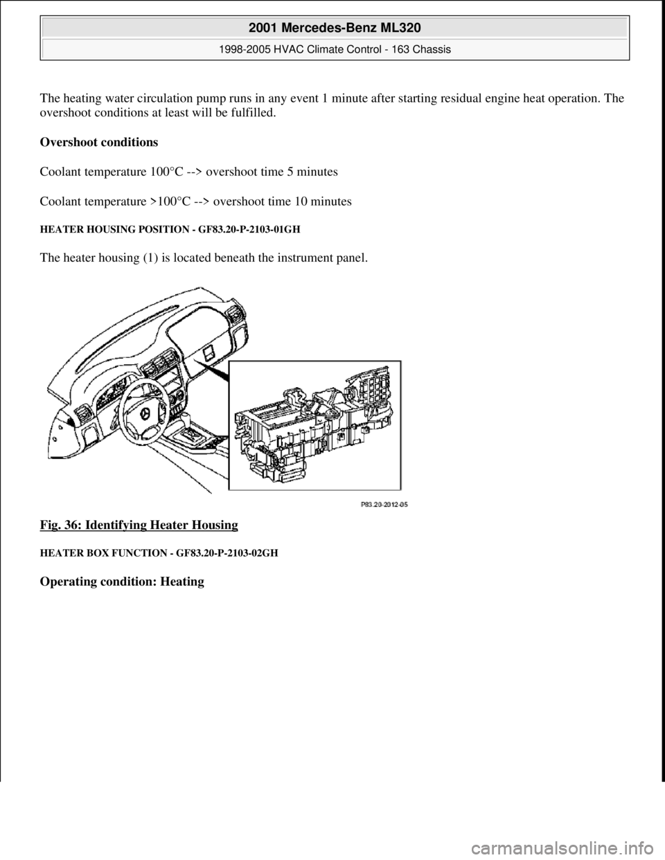
HEATER HOUSING POSITION - GF83.20-P-2103-01GH
The heater housing (1) is located beneath the instrument panel.
Fig. 36: Identifying Heater Housing
HEATER BOX FUNCTION - GF83.20-P-2103-02GH
Operating condition: Heating
2001 Mercedes-Benz ML320
1998-2005 HVAC Climate Control - 163 Chassis
me
Saturday, October 02, 2010 3:23:15 PMPage 46 © 2006 Mitchell Repair Information Company, LLC.