1997 MERCEDES-BENZ ML430 coolant temperature
[x] Cancel search: coolant temperaturePage 2409 of 4133
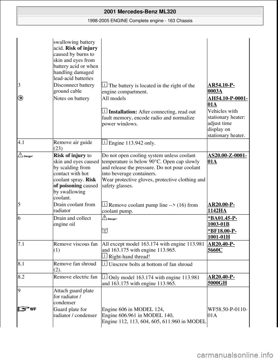
swallowing battery
acid. Risk of injury
caused by burns to
skin and eyes from
battery acid or when
handling damaged
lead-acid batteries
3Disconnect battery
ground cable The battery is located in the right of the
engine compartment.AR54.10-P-
0003A
Notes on batteryAll modelsAH54.10-P-0001-
01A
Installation: After connecting, read out
fault memory, encode radio and normalize
power windows.Vehicles with
stationary heater:
adjust time
display on
stationary heater.
4.1Remove air guide
(23) Engine 113.942 only.
Risk of injury to
skin and eyes caused
by scalding from
contact with hot
coolant spray. Risk
of poisoning caused
by swallowing
coolant.Do not open cooling system unless coolant
temperature is below 90° C. Open cap slowly
and release the pressure. Do not pour coolant
into beverage containers.
Wear protective gloves, pr otective clothing and
safety glasses.AS20.00-Z-0001-
01A
5Drain coolant from
radiator Remove coolant pump line --> (16) from
coolant pump.AR20.00-P-
1142HA
6Drain and collect
engine oil *BA01.45-P-
1003-01B
*BF18.00-P-
1001-01H
7.1Remove viscous fan
(1)All except model 163.174 with engine 113.981
and 163.175 with engine 113.965.
Right-hand thread!AR20.40-P-
5660C
8.1Remove fan shroud
(2). Unscrew bolts at bottom of fan shroud
8.2Remove electric fan Only model 163.174 with engine 113.981
and 163.175 with engine 113.965.AR20.40-P-
5000GH
9Attach guard plate
for radiator /
condenser
Guard plate for
radiator / condenserEngine 606 in MODEL 124,
Engine 606.961 in MODEL 140,
Engine 112, 113, 604, 605, 611.960 in MODEL WF58.50-P-0110-
01A
2001 Mercedes-Benz ML320
1998-2005 ENGINE Complete engine - 163 Chassis
me
Saturday, October 02, 2010 3:17:56 PMPage 53 © 2006 Mitchell Repair Information Company, LLC.
Page 2441 of 4133
stationary heater timer.
Notes on batteryAll modelsAH54.10-P-0001-
01A
Risk of death caused
by vehicle slipping
or toppling off of the
lifting platform.Align vehicle between the columns of the
lifting platform and pos ition the four support
plates below the lifti ng platform support points
specified by the vehicle manufacturer.AS00.00-Z-0010-
01A
2Place the vehicle on
lifting platform AR00.60-P-
1000GH
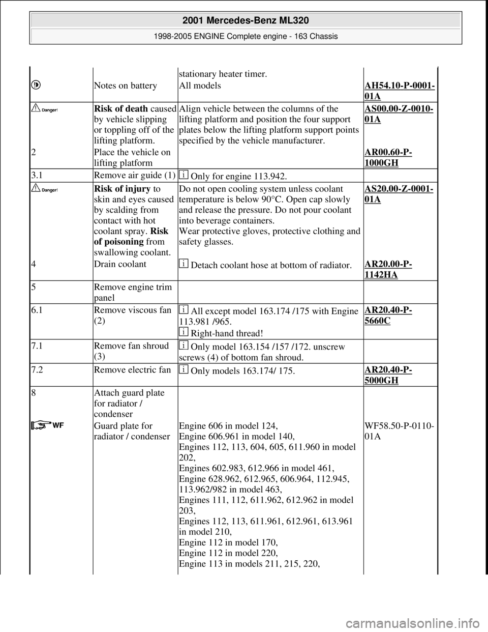
3.1Remove air guide (1) Only for engine 113.942.
Risk of injury to
skin and eyes caused
by scalding from
contact with hot
coolant spray. Risk
of poisoning from
swallowing coolant.Do not open cooling system unless coolant
temperature is below 90° C. Open cap slowly
and release the pressure. Do not pour coolant
into beverage containers.
Wear protective gloves, pr otective clothing and
safety glasses.AS20.00-Z-0001-
01A
4Drain coolant Detach coolant hose at bottom of radiator.AR20.00-P-
1142HA
5Remove engine trim
panel
6.1Remove viscous fan
(2) All except model 163.174 /175 with Engine
113.981 /965.
Right-hand thread!AR20.40-P-
5660C
7.1Remove fan shroud
(3) Only model 163.154 /157 /172. unscrew
screws (4) of bottom fan shroud.
7.2Remove electric fan Only models 163.174/ 175.AR20.40-P-
5000GH
8Attach guard plate
for radiator /
condenser
Guard plate for
radiator / condenserEngine 606 in model 124,
Engine 606.961 in model 140,
Engines 112, 113, 604, 605, 611.960 in model
202,
Engines 602.983, 612.966 in model 461,
Engine 628.962, 612.965, 606.964, 112.945,
113.962/982 in model 463,
Engines 111, 112, 611.962, 612.962 in model
203,
Engines 112, 113, 611.961, 612.961, 613.961
in model 210,
Engine 112 in model 170,
Engine 112 in model 220,
Engine 113 in models 211, 215, 220, WF58.50-P-0110-
01A
2001 Mercedes-Benz ML320
1998-2005 ENGINE Complete engine - 163 Chassis
me
Saturday, October 02, 2010 3:17:57 PMPage 85 © 2006 Mitchell Repair Information Company, LLC.
Page 2454 of 4133
poisoning and
caustic burns
caused by
swallowing
battery acid. Risk
of injury caused
by burns to skin
and eyes from
battery acid or
when handling
damaged lead-
acid batteries
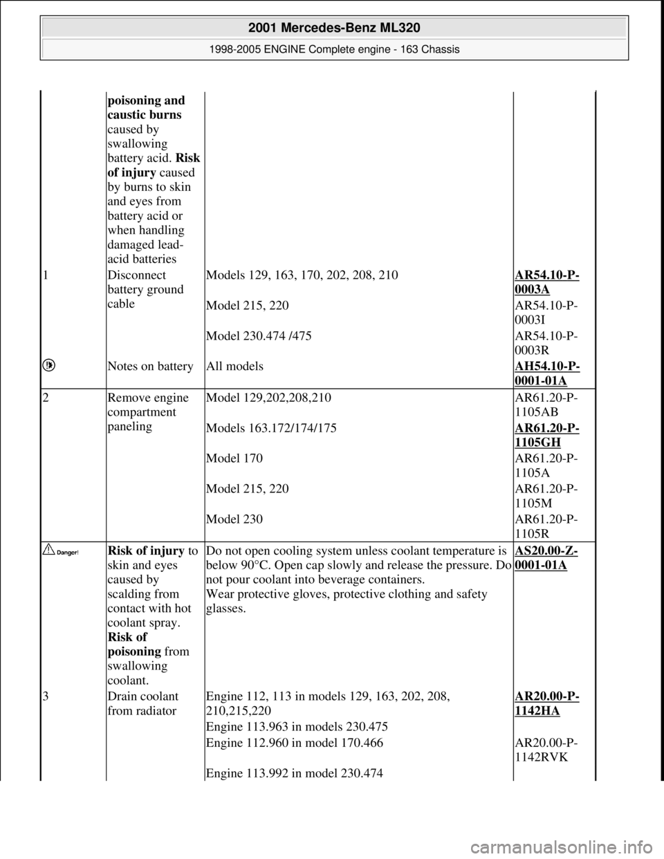
1Disconnect
battery ground
cableModels 129, 163, 170, 202, 208, 210AR54.10-P-
0003A
Model 215, 220AR54.10-P-
0003I
Model 230.474 /475AR54.10-P-
0003R
Notes on batteryAll modelsAH54.10-P-
0001-01A
2Remove engine
compartment
panelingModel 129,202,208,210AR61.20-P-
1105AB
Models 163.172/174/175AR61.20-P-
1105GH
Model 170AR61.20-P-
1105A
Model 215, 220AR61.20-P-
1105M
Model 230AR61.20-P-
1105R
Risk of injury to
skin and eyes
caused by
scalding from
contact with hot
coolant spray.
Risk of
poisoning from
swallowing
coolant.Do not open cooling system unless coolant temperature is
below 90°C. Open cap slowly and release the pressure. Do
not pour coolant into beverage containers.
Wear protective gloves, protec tive clothing and safety
glasses.
AS20.00-Z-
0001-01A
3Drain coolant
from radiatorEngine 112, 113 in models 129, 163, 202, 208,
210,215,220AR20.00-P-
1142HA
Engine 113.963 in models 230.475
Engine 112.960 in model 170.466AR20.00-P-
1142RVK
Engine 113.992 in model 230.474
2001 Mercedes-Benz ML320
1998-2005 ENGINE Complete engine - 163 Chassis
me
Saturday, October 02, 2010 3:17:57 PMPage 98 © 2006 Mitchell Repair Information Company, LLC.
Page 2460 of 4133
Engine 113.992 in model 230.474AR14.30-P-
7251RVK
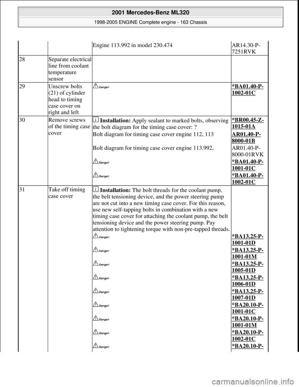
28Separate electrical
line from coolant
temperature
sensor
29Unscrew bolts
(21) of cylinder
head to timing
case cover on
right and left *BA01.40-P-
1002-01C
30Remove screws
of the timing case
cover Installation: Apply sealant to marked bolts, observing
the bolt diagram for th e timing case cover: ?*BR00.45-Z-
1015-01A
Bolt diagram for timing case cover engine 112, 113AR01.40-P-
8000-01B
Bolt diagram for timing case cover engine 113.992,AR01.40-P-
8000-01RVK
*BA01.40-P-
1001-01C
*BA01.40-P-
1002-01C
31Take off timing
case cover Installation: The bolt threads for the coolant pump,
the belt tensioning device, and the power steering pump
are not cut into a new timing case cover. For this reason,
use new self-tapping bolts in combination with a new
timing case cover for attaching the coolant pump, the belt
tensioning device and th e power steering pump. Pay
attention to tightening torque with non-pre-tapped threads.
*BA13.25-P-
1001-01D
*BA13.25-P-
1001-01M
*BA13.25-P-
1005-01D
*BA13.25-P-
1006-01D
*BA13.25-P-
1007-01D
*BA20.10-P-
1001-01C
*BA20.10-P-
1001-01M
*BA20.10-P-
1002-01C
*BA20.10-P-
2001 Mercedes-Benz ML320
1998-2005 ENGINE Complete engine - 163 Chassis
me
Saturday, October 02, 2010 3:17:57 PMPage 104 © 2006 Mitchell Repair Information Company, LLC.
Page 2583 of 4133
AR07.16-P-1100MM
Remove, install fuel cooler
5.11.99
ENGINE
612.963 in MODELS 163.113
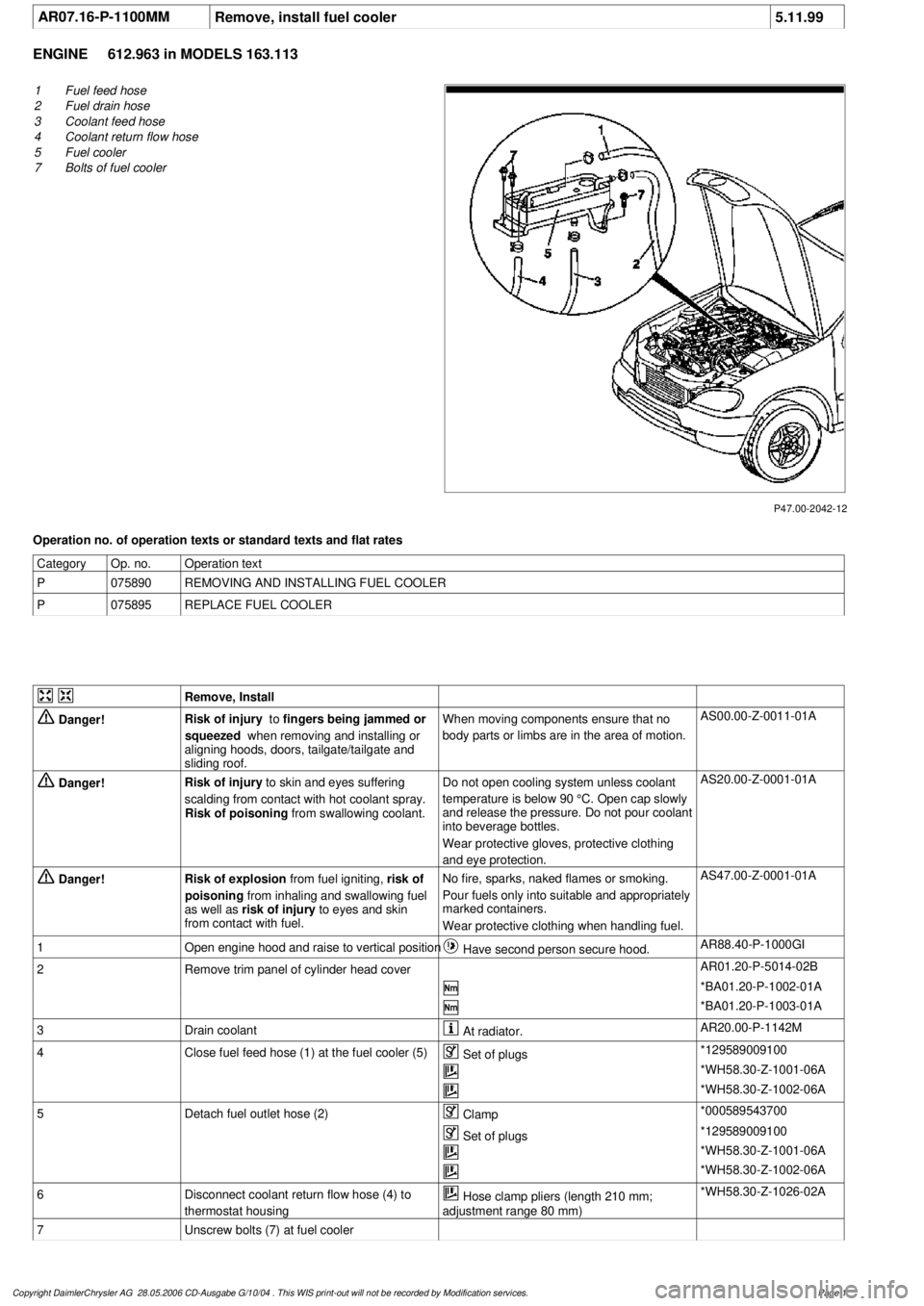
P47.00-2042-12
1
Fuel feed hose
2
Fuel drain hose
3
Coolant feed hose
4
Coolant return flow hose
5
Fuel cooler
7
Bolts of fuel cooler
Operation no. of operation texts or standard texts and flat rates
Category
Op. no.
Operation text
P
075890
REMOVING AND INSTALLING FUEL COOLER
P
075895
REPLACE FUEL COOLER
Remove, Install
Danger!
Risk of injury
to
fingers being jammed or
squeezed
when removing and installing or
aligning hoods, doors, tailgate/tailgate and
sliding roof.
When moving components ensure that no
body parts or limbs are in the area of motion.
AS00.00-Z-0011-01A
Danger!
Risk of injury
to skin and eyes suffering
scalding from contact with hot coolant spray.
Risk of poisoning
from swallowing coolant.
Do not open cooling system unless coolant
temperature is below 90 °C. Open cap slowly
and release the pressure. Do not pour coolant
into beverage bottles.
Wear protective gloves, protective clothing
and eye protection.
AS20.00-Z-0001-01A
Danger!
Risk of explosion
from fuel igniting,
risk of
poisoning
from inhaling and swallowing fuel
as well as
risk of injury
to eyes and skin
from contact with fuel.
No fire, sparks, naked flames or smoking.
Pour fuels only into suitable and appropriately
marked containers.
Wear protective clothing when handling fuel.
AS47.00-Z-0001-01A
1
Open engine hood and raise to vertical position
Have second person secure hood.
AR88.40-P-1000GI
2
Remove trim panel of cylinder head cover
AR01.20-P-5014-02B
*BA01.20-P-1002-01A
*BA01.20-P-1003-01A
3
Drain coolant
At radiator.
AR20.00-P-1142M
4
Close fuel feed hose (1) at the fuel cooler (5)
Set of plugs
*129589009100
*WH58.30-Z-1001-06A
*WH58.30-Z-1002-06A
5
Detach fuel outlet hose (2)
Clamp
*000589543700
Set of plugs
*129589009100
*WH58.30-Z-1001-06A
*WH58.30-Z-1002-06A
6
Disconnect coolant return flow hose (4) to
thermostat housing
Hose clamp pliers (length 210 mm;
adjustment range 80 mm)
*WH58.30-Z-1026-02A
7
Unscrew bolts (7) at fuel cooler
Copyright DaimlerChrysler AG 28.05.2006 CD-Ausgabe G/10/04 . This WIS print-out will not be recorde
d by Modification services.
Page 1
Page 2584 of 4133

8
Disconnect coolant feed hose (3) to fuel cooler
Raise fuel cooler.
Hose clamp pliers (length 210 mm;
adjustment range 80 mm)
*WH58.30-Z-1026-02A
9
Install in the reverse order
Danger!
Risk of accident
as vehicle may start off by
itself with the engine running.
Risk of injury
as working around the engine during start-up
or while running may result in contusions and
burns
Secure vehicle to prevent it from moving off
by itself.
Wear closed and tight-fitting work clothes.
Do not grasp hot or rotating parts.
AS00.00-Z-0005-01A
10
Pour in coolant
*BF20.00-P-1001-02E
Switch heater to maximum and warm up
engine at moderate revs. Top up coolant
constantly at coolant expansion reservoir.
Close coolant expansion reservoir once
coolant temperature is 60-70 °C.
Note on coolant level
Models 124, 129, 140, 168, 170, 202, 208,
210, 220, 463
AH20.00-P-1142-01A
11
Inspect cooling system for leaks
AR20.00-P-1010HA
12
Run engine and inspect fuel system for leaks
Crankcase ventilation, cylinder head cover
Number
Designation
Engine
612.963
BA01.20-P-1002-01A
Screw of trim panel of cylinder head cover
to cylinder head cover
NM
10
BA01.20-P-1003-01A
Screw attaching cover panel to charge air
distribution pipe
NM
10
Cooling system
Number
Designation
Engine
612.963
BF20.00-P-1001-02E
Cooling system
Total capacity
Liter
Y
11,0
Capacity of anticorrosion/
antifreeze agent down to -37 °C
Liter
Y
5,5
Capacity of anticorrosion/
antifreeze agent down to -45 °C
Liter
Y
6,25
Specifications for Service
Products
SheetBB00.40-P-0310-01A
SheetBB00.40-P-0325-02A
129 589 00 91 00
Set of closure plugs
Circuit
000 589 54 37 00
Commercially available tools
(see Workshop Equipment Manual)
Number
Designation
Make (e.g.) g.)
Order number
Copyright DaimlerChrysler AG 28.05.2006 CD-Ausgabe G/10/04 . This WIS print-out will not be recorde
d by Modification services.
Page 2
Page 2842 of 4133
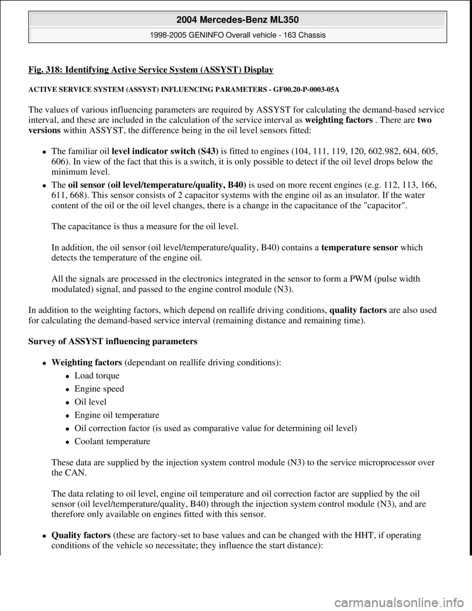
Fig. 318: Identifying Active Service System (ASSYST) Display
ACTIVE SERVICE SYSTEM (ASSYST) INFLUENCING PARAMETERS - GF00.20-P-0003-05A
The values of various influencing parameters are required by ASSYST for calculating the demand-based service
interval, and these are included in the calculation of the service interval as weighting factors . There are two
versions within ASSYST, the difference being in the oil level sensors fitted:
The familiar oil level indicator switch (S43) is fitted to engines (104, 111, 119, 120, 602.982, 604, 605,
606). In view of the fact that this is a switch, it is only possible to detect if the oil level drops below the
minimum level.
The oil sensor (oil level/temperature/quality, B40) is used on more recent engines (e.g. 112, 113, 166,
611, 668). This sensor consists of 2 capacitor systems with the engine oil as an insulator. If the water
content of the oil or the oil level changes, there is a change in the capacitance of the "capacitor".
The capacitance is thus a measure for the oil level.
In addition, the oil sensor (oil level/temperature/quality, B40) contains a temperature sensor which
detects the temperature of the engine oil.
All the signals are processed in the electronics integrated in the sensor to form a PWM (pulse width
modulated) signal, and passed to the engine control module (N3).
In addition to the weighting factors, which depend on reallife driving conditions, quality factors are also used
for calculating the demand-based service interval (remaining distance and remaining time).
Survey of ASSYST influencing parameters
Weighting factors (dependant on reallife driving conditions):
Load torque
Engine speed
Oil level
Engine oil temperature
Oil correction factor (is used as comparative value for determining oil level)
Coolant temperature
These data are supplied by the injection system control module (N3) to the service microprocessor over
the CAN.
The data relating to oil level, engine oil temperature and oil correction factor are supplied by the oil
sensor (oil level/temperature/quality, B40) through the injection system control module (N3), and are
therefore only available on engines fitted with this sensor.
Quality factors (these are factory-set to base values and can be changed with the HHT, if operating
conditions of the vehicle so necessitate; they influence the start distance):
2004 Mercedes-Benz ML350
1998-2005 GENINFO Overall vehicle - 163 Chassis
me
Saturday, October 02, 2010 3:47:47 PMPage 197 © 2006 Mitchell Repair Information Company, LLC.
Page 2845 of 4133
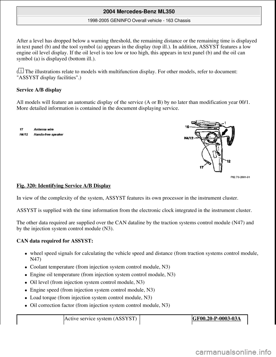
After a level has dropped below a warning threshold, the remaining distance or the remaining time is displayed
in text panel (b) and the tool symbol (a) appears in the display (top ill.). In addition, ASSYST features a low
engine oil level display. If the oil level is too low or too high, this appears in text panel (b) and the oil can
symbol (a) is displayed (bottom ill.).
( The illustrations relate to models with multifunction display. For other models, refer to document:
"ASSYST display facilities".)
Service A/B display
All models will feature an automatic display of the service (A or B) by no later than modification year 00/1.
More detailed information is contained in the document displaying service.
Fig. 320: Identifying Service A/B Display
In view of the complexity of the system, ASSYST features its own processor in the instrument cluster.
ASSYST is supplied with the time information from the electronic clock integrated in the instrument cluster.
The other data required are supplied over the CAN dataline by the traction systems control module (N47) and
by the injection system control module (N3).
CAN data required for ASSYST:
wheel speed signals for calculating the vehicle speed and distance (from traction systems control module,
N47)
Coolant temperature (from injection system control module, N3)
Engine oil temperature (from injection system control module, N3)
Oil level (from injection system control module, N3)
Engine speed (from injection system control module, N3)
Load torque (from injection system control module, N3)
Oil correction factor (from injection system control module, N3)
Active service system (ASSYST) GF00.20-P-0003-03A
2004 Mercedes-Benz ML350
1998-2005 GENINFO Overall vehicle - 163 Chassis
me
Saturday, October 02, 2010 3:47:47 PMPage 200 © 2006 Mitchell Repair Information Company, LLC.