Page 493 of 4133

26
Central locking system
Te ch n ica l
data
Instruments
and controls Operation
Driving Instrument
cluster display Practical hints Car care Index
General notes on the central locking system
If the key in the steering lock is in position 1 or 2, the
vehicle cannot be locked or unlocked with the remote
control.
If the vehicle cannot be locked or unlocked:
• Check the batteries of the remote control, see
page 270.
• Synchronize the remote control, see page 271. Central locking system
(Radio frequency remote control)
The master key has an integrated radio frequency
remote control.
Due to the extended operational range of the remote
control, it could be possible to unintentionally lock or
unlock the vehicle by pressing the transmit button.
The vehicle doors, liftgate and fuel filler flap can be
centrally locked and unlocked via remote control.
With vehicle centrally locked, the liftgate can also be
unlocked by using the remote control.
If the key in the steering lock is in position 1 or 2, the
vehicle cannot be locked or unlocked with the remote
control.
Page 494 of 4133
27
Central locking system
Te ch n ica l
data
Instruments
and controls Operation
Driving Instrument
cluster display Practical hints Car care Index
1
Transmit button
‹ Locking
ΠUnlocking
Š Unlocking liftgate
2 PANIC button
3 Release button for master key Locking and unlocking with remote control
Unlocking :
Press transmit button Πonce. All turn signal lamps
blink once to indicate that the driver’s door and fuel
filler flap are unlocked.
The antitheft alarm system is also deactivated.
Press transmit button Πa second time to unlock
remaining doors and liftgate.
Notes:
If the fuel filler flap cannot be opened, see page 274.
If within 40 seconds of unlocking with the remote
control, neither door nor liftgate is opened or the key is
not inserted in the steering lock, the vehicle will
automatically lock and reactivate the antitheft alarm
system.
Page 498 of 4133
31
Central locking system
Te ch n ica l
data
Instruments
and controls Operation
Driving Instrument
cluster display Practical hints Car care Index
Each individual door and the liftgate must be locked
with the respective door lock button – the driver’s door
can only be locked when it is closed.
Notes:
The alarm sounds when unlocking the driver’s door.
Cancel alarm by turning key in steering lock to
position 1, or with the remote control by pressing
button Œ.
If the vehicle has previously been locked from the
outside, only the door being opened from the inside will
unlock, and the alarm will come on. The remaining
doors, the liftgate and fuel filler flap remain locked.
In case of a malfunction in the central locking system
the doors can be locked and unlocked individually. To lock, push down lock buttons and turn mechanical
key in driver’s door lock to position 3. In addition lock
the liftgate.
To unlock, pull inside door handles and turn mechanical
key in driver’s door lock to position 2.
Rear doors, previously centrally locked, can be opened
from inside by first unlocking the vehicle with the
central locking switch, see page 32, or by first pulling
up the door lock button.
If the fuel filler flap cannot be opened, see page 274.
Page 544 of 4133
77
Instrument cluster
Te ch n ica l
data
Instruments
and controls Operation
Driving Instrument
cluster display Practical hints Car care Index
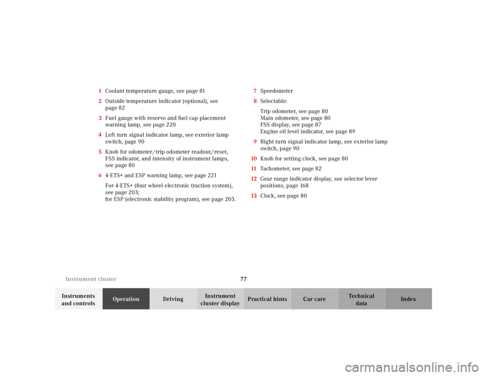
1
Coolant temperature gauge, see page 81
2 Outside temperature indicator (optional), see
page 82
3 Fuel gauge with reserve and fuel cap placement
warning lamp, see page 220
4 Left turn signal indicator lamp, see exterior lamp
switch, page 90
5 Knob for odometer / trip odometer readout / reset,
FSS indicator, and intensity of instrument lamps,
see page 80
6 4-ETS+ and ESP warning lamp, see page 221
For 4-ETS+ (four wheel electronic traction system),
see page 203;
for ESP (electronic stability program), see page 205. 7
Speedometer
8 Selectable:
Trip odometer, see page 80
Main odometer, see page 80
FSS display, see page 87
Engine oil level indicator, see page 89
9 Right turn signal indicator lamp, see exterior lamp
switch, page 90
10 Knob for setting clock, see page 80
11 Tachometer, see page 82
12 Gear range indicator display, see selector lever
positions, page 168
13 Clock, see page 80
Page 546 of 4133
79
Instrument cluster
Te ch n ica l
data
Instruments
and controls Operation
Driving Instrument
cluster display Practical hints Car care Index
If the “CHECK ENGINE” malfunction
indicator lamp comes on when the engine is
running, it indicates a malfunction of the
fuel management system, emission control
system, systems which impact emissions, or
the fuel cap is not closed tight. In all cases,
we recommend that you have the
malfunction checked as soon as possible, see
page 218. Additional function indicator lamps
(in the odometer display)
FSS indicator (Service A), see page 87
FSS indicator (Service B), see page 87
The symbols appear in the main odometer display field
prior to the next suggested service. Depending on
operating conditions throughout the year, the next
service is calculated and displayed in days or distance
remaining. See page 87 for notes on the flexible service
system (FSS).
CHECK
ENGINE
Page 549 of 4133
82
Instrument cluster
Te ch n ica l
data
Instruments
and controls Operation
Driving Instrument
cluster display Practical hints Car care Index
Outside temperature indicator
The temperature sensor is located in the front bumper
area. Due to its location, the sensor can be affected by
road or engine heat during idling or slow driving. This
means that the accuracy of the displayed temperature
can only be verified by comparison to a thermometer
placed next to the sensor, not by comparison to external
displays (e.g. bank signs etc.).
Adaptation to ambient temperature takes place in steps
and depends on the prevailing driving conditions (stop-
and-go or moderate, constant driving) and amount of
temperature change. Tachometer
The tachometer displays the present engine speed in
revolutions per minute (RPM).
To help protect the engine, the fuel supply is interrupted
if the engine is operated above its specified limit.
Wa r n i n g !
The outside temperature indicator is not designed
to serve as an Ice-Warning Device and is therefore
unsuitable for that purpose. Indicated
temperatures just above the freezing point do not
guarantee that the road surface is free of ice.
Page 550 of 4133
83
Trip computer
Te ch n ica l
data
Instruments
and controls Operation
Driving Instrument
cluster display Practical hints Car care Index
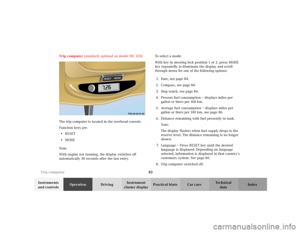
Trip computer
(standard; optional on model ML 320)
The trip computer is located in the overhead console.
Function keys are: • RESET
• MODE
Note:
With engine not running, the display switches off
automatically 30 seconds after the last entry. To select a mode:
With key in steering lock position 1 or 2, press MODE
key repeatedly to illuminate the display and scroll
through menu for one of the following options:
1. Date, see page 84.
2. Compass, see page 84.
3. Stop watch, see page 86.
4. Present fuel consumption – displays miles per gallon or liters pe r 100 km.
5. Average fuel consumption – displays miles per gallon or liters per 100 km, see page 86.
6. Distance remaining with fuel presently in tank. Note:
The display f lashes when fuel supply drops to the
reserve level. The distance remaining is no longer
shown.
7. Language – Press RESET key until the desired language is displayed. Depending on language
selected, information is displayed in that country’s
customary system. See page 86.
8. Trip computer switched off.
MODE
Page 553 of 4133
86
Trip computer
Te ch n ica l
data
Instruments
and controls Operation
Driving Instrument
cluster display Practical hints Car care Index
To calibrate the compass:
If the vehicle was exposed to a significant magnetic
zone, such as high voltage power lines, the compass
may have to be calibrated.
Calibration of the compass should be done in an area
free of steel superstructures and power lines. All
electrical consumers (e.g. exterior lamps, climate
control, etc.) should be switched off, doors and liftgate
closed. Do not open or close the roof. An open door or
liftgate triggers the display “–––”.
1. Start and run the engine.
2. Press MODE key repeatedly until the compass display appears in the trip computer display.
3. Press RESET key to select the compass zone display.
4. Press RESET repeatedly until the correct zone, as determined from the zone map (see page 85), is
shown in the display.
5. Press MODE key, “CAL–” appears in the display.
6. Press and hold RESET for a minimum of 2 seconds. 7. Without interruption drive two or more full circles
at a speed between 3 mph (5 km / h) and 7 mph
(10 km / h) during which the message “CAL” is
replaced with a compass bearing (e.g. N, SW etc.),
immediately followed by three full circles at the
same speed, with only the rear window defroster
switched on. The defroster can be switched off
again. The calibration of the compass is now
complete.
• Stop watch –
Press RESET key to start the count. Press again to
stop the count. Press and hold RESET key to reset
sto p watch.
• Average fuel consumption –
Press RESET key to delete present reading.
• Language –
Press RESET key to set the language used in the
display.