Page 1600 of 4133
RADIO/NAVIGATION MODULE , LOCATION/PURPOSE/DESIGN/FUNCTION - GF82.61-P-4109GI
MODEL 163 as of 1.9.01 with CODE (522) Modular cont rol system (MCS) radio USA with CODE (357)
Navigation system - additional uni t with CODE (818b) Single CD player - additional unit with CODE
(491) U.S. version
Fig. 60: Identifying Radio And Navigation Module
Fig. 61: Identifying Radio And Navigation Module Connectors
Radio and navigation
module, location GF82.61-P-4109-01GI
Radio and navigation
module, purposeCentral control for the
following systems:
Radio, CC player, CD
player (optional) and
2001 Mercedes-Benz ML320
1998-2005 ACCESSORIES & BODY, CAB Electr ical System - Body - 163 Chassis
me
Saturday, October 02, 2010 3:30:05 PMPage 105 © 2006 Mitchell Repair Information Company, LLC.
Page 1602 of 4133
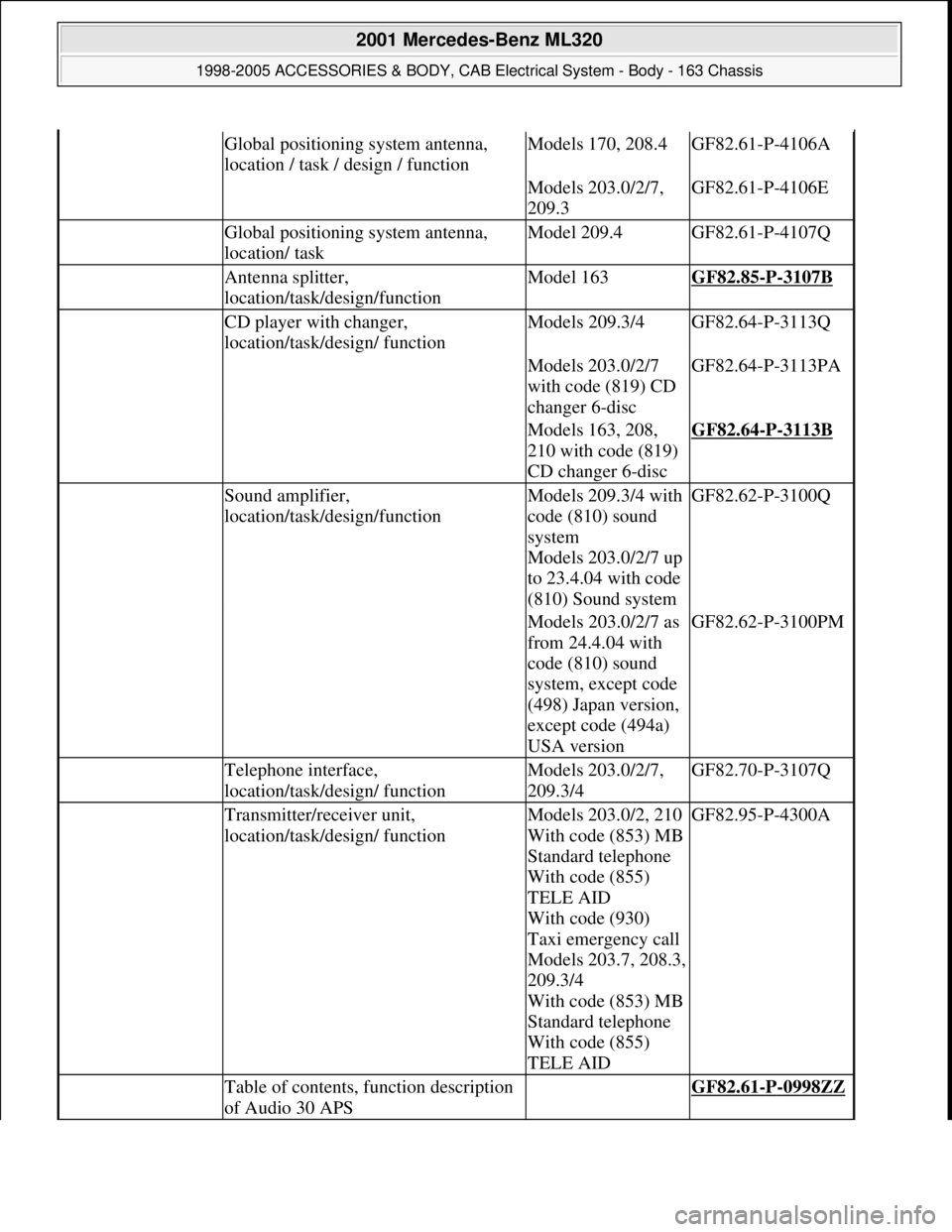
Global positioning system antenna,
location / task / design / functionModels 170, 208.4GF82.61-P-4106A
Models 203.0/2/7,
209.3GF82.61-P-4106E
Global positioning system antenna,
location/ taskModel 209.4GF82.61-P-4107Q
Antenna splitter,
location/task/design/functionModel 163GF82.85-P-3107B
CD player with changer,
location/task/design/ functionModels 209.3/4GF82.64-P-3113Q
Models 203.0/2/7
with code (819) CD
changer 6-discGF82.64-P-3113PA
Models 163, 208,
210 with code (819)
CD changer 6-discGF82.64-P-3113B
Sound amplifier,
location/task/design/functionModels 209.3/4 with
code (810) sound
system
Models 203.0/2/7 up
to 23.4.04 with code
(810) Sound systemGF82.62-P-3100Q
Models 203.0/2/7 as
from 24.4.04 with
code (810) sound
system, except code
(498) Japan version,
except code (494a)
USA versionGF82.62-P-3100PM
Telephone interface,
location/task/design/ functionModels 203.0/2/7,
209.3/4GF82.70-P-3107Q
Transmitter/receiver unit,
location/task/design/ functionModels 203.0/2, 210
With code (853) MB
Standard telephone
With code (855)
TELE AID
With code (930)
Taxi emergency call
Models 203.7, 208.3,
209.3/4
With code (853) MB
Standard telephone
With code (855)
TELE AIDGF82.95-P-4300A
Table of contents, function description
of Audio 30 APS GF82.61-P-0998ZZ
2001 Mercedes-Benz ML320
1998-2005 ACCESSORIES & BODY, CAB Electrical System - Body - 163 Chassis
me
Saturday, October 02, 2010 3:30:05 PMPage 107 © 2006 Mitchell Repair Information Company, LLC.
Page 1616 of 4133
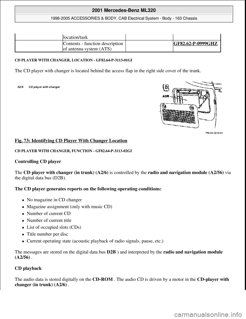
CD PLAYER WITH CHANGER, LOCATION - GF82.64-P-3113-01GI
The CD player with changer is located behind the access flap in the right side cover of the trunk.
Fig. 73: Identifying CD Player With Changer Location
CD PLAYER WITH CHANGER, FUNCTION - GF82.64-P-3113-02GI
Controlling CD player
The CD player with changer (in trunk) (A2/6) is controlled by the radio and navigation module (A2/56)via
the digital data bus (D2B).
The CD player generates reports on the following operating conditions:
No magazine in CD changer
Magazine assignment (only with music CD)
Number of current CD
Number of current title
List of occupied slots (CDs)
Title number per disc
Current operating state (acoustic playback of radio signals, pause, etc.)
The messages are stored on the digital data bus D2B ) and interpreted by the radio and navigation module
(A2/56) .
CD playback
The audio data is stored digitally on the CD-ROM . The audio CD is driven by a motor in the CD-player with
changer (in trunk) (A2/6) .
location/task
Contents - function description
of antenna system (ATS) GF82.62-P-0999GHZ
2001 Mercedes-Benz ML320
1998-2005 ACCESSORIES & BODY, CAB Electrical System - Body - 163 Chassis
me
Saturday, October 02, 2010 3:30:06 PMPage 121 © 2006 Mitchell Repair Information Company, LLC.
Page 1617 of 4133
The laser-optical device scans the non-labeled side of the rotating CDwithout making contact and converts the
digital optical signals into electrical signals. Small interruptions in the data flow of the laser optics caused by
scratches or contamination on the audio CD are compensated by the D/A converter supplementing the missing
values .
The electrical signals are then decoded in the CD player with changer (in trunk) (A2/6) and transmitted via
the digital data bus ( D2B ) to the radio and navigation module (A2/56) via the audio signal processing or
when the sound amplifier (A2/13) (code 810) is installed to the loudspeakers.
Jumps and interruptions during playback
On bad roads or in the event of heavy vibrations , jumps and interruptions can occur during playback. In
such cases do not start CD mode until better road conditions are present.
In the event of wet weather conditions and strong deviations in the ambient temperatures moisture can collect in
the CD player housing (condensation formation). This could also lead to malfunctions in the playback. In such
cases provide for sufficient ventilation of the CD player and the trunk.
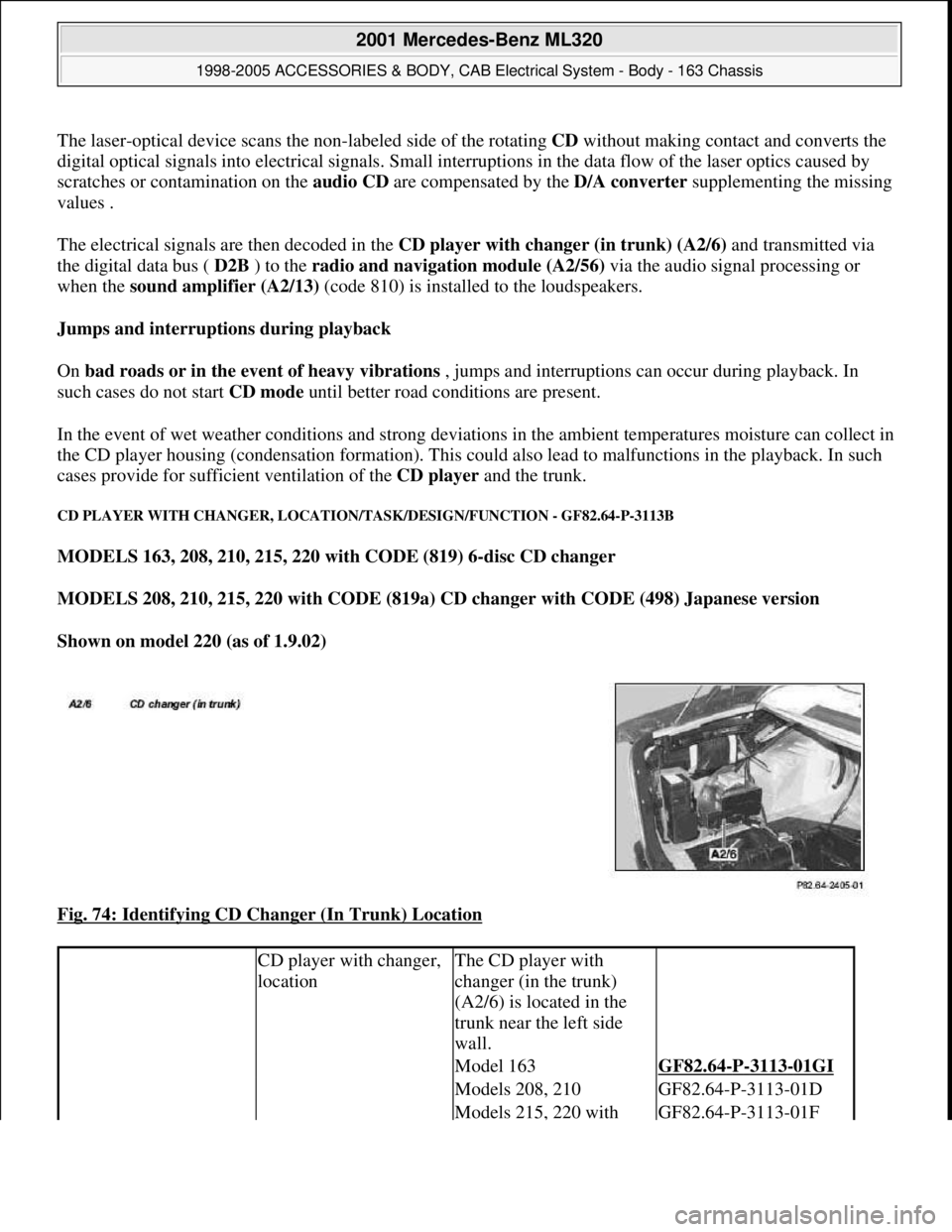
CD PLAYER WITH CHANGER, LOCATION/TASK/DESIGN/FUNCTION - GF82.64-P-3113B
MODELS 163, 208, 210, 215, 220 with CODE (819) 6-disc CD changer
MODELS 208, 210, 215, 220 with CODE (819a) CD changer with CODE (498) Japanese version
Shown on model 220 (as of 1.9.02)
Fig. 74: Identifying CD Changer (In Trunk) Location
CD player with changer,
locationThe CD player with
changer (in the trunk)
(A2/6) is located in the
trunk near the left side
wall.
Model 163GF82.64-P-3113-01GI
Models 208, 210GF82.64-P-3113-01D
Models 215, 220 with GF82.64-P-3113-01F
2001 Mercedes-Benz ML320
1998-2005 ACCESSORIES & BODY, CAB Electrical System - Body - 163 Chassis
me
Saturday, October 02, 2010 3:30:06 PMPage 122 © 2006 Mitchell Repair Information Company, LLC.
Page 1618 of 4133
CD PLAYER WITH CHANGER, LOCATION/PURPOSE/DESIGN/FUNCTION - GF82.64-P-3113GI
MODEL 163 with CODE (522) Modular control system (MCS) radio USA with CODE (357) Navigation
system - additional unit with CODE (818b) Single CD player - additional unit with CODE (819) 6-disk
CD changer in trunk with CODE (491) U.S. version
code 498
Models 215, 220 without
code 498GF82.64-P-3113-01E
CD player with changer,
purposePlaying audio
compact discs (CD)
Changing CDs
contained in the
magazine
CD player with changer,
design6-slot CD changer
magazine
only: 12-slot
CD changer
magazine
Digital Data Bus
(D2B) interface
The factory planned
installation position for
the CD changer is vertical,
whereby other installation
positions are possible by
adaptation of the spring
locations.
CD player with changer,
functionModels 208, 210GF82.64-P-3113-02C
Model 215, 220GF82.64-P-3113-02B
2001 Mercedes-Benz ML320
1998-2005 ACCESSORIES & BODY, CAB Electrical System - Body - 163 Chassis
me
Saturday, October 02, 2010 3:30:06 PMPage 123 © 2006 Mitchell Repair Information Company, LLC.
Page 1619 of 4133
Fig. 75: Identifying CD Player With Changer
GPS/CTEL ROOF ANTENNA, LOCATION - GF82.70-P-4111-01GH
Model 163
Location, illustration valid up to 31.08.01:
The CTEL and GPS roof antenna (A2/49) is mounted on the rear of the roof in the middle of the vehicle.
CD player with changer,
location GF82.64-P-3113-01GI
CD player with changer,
purposePlaying audio
compact discs (CD).
Changing CD's
contained in the
magazine
CD player with changer,
designCD changer
magazine for 6 CD's
Digital data bus
(D2B) interface
The installation position
of the CD changer
predefined by the factory
is vertical, however
another installation
location is also possible
by adapting the spring
location
CD player with changer,
function GF82.64-P-3113-02GI
2001 Mercedes-Benz ML320
1998-2005 ACCESSORIES & BODY, CAB Electrical System - Body - 163 Chassis
me
Saturday, October 02, 2010 3:30:06 PMPage 124 © 2006 Mitchell Repair Information Company, LLC.
Page 1625 of 4133
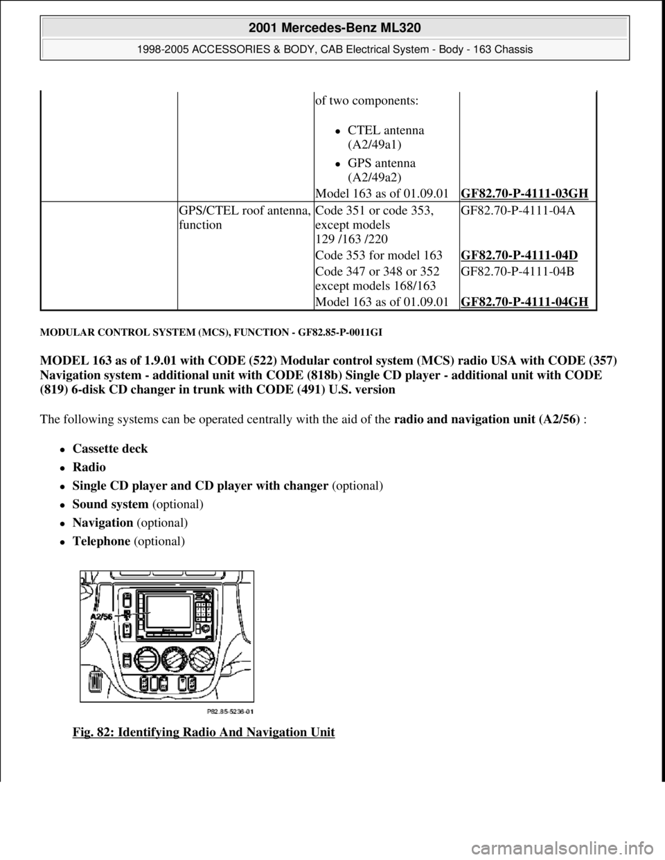
MODULAR CONTROL SYSTEM (MCS), FUNCTION - GF82.85-P-0011GI
MODEL 163 as of 1.9.01 with CODE (522) Modular control system (MCS) radio USA with CODE (357)
Navigation system - additional unit with CODE (818b) Single CD player - additional unit with CODE
(819) 6-disk CD changer in trunk with CODE (491) U.S. version
The following systems can be operated centrally with the aid of the radio and navigation unit (A2/56) :
Cassette deck
Radio
Single CD player and CD player with changer (optional)
Sound system (optional)
Navigation (optional)
Telephone (optional)
Fig. 82: Identifying Radio And Navigation Unit
of two components:
CTEL antenna
(A2/49a1)
GPS antenna
(A2/49a2)
Model 163 as of 01.09.01GF82.70-P-4111-03GH
GPS/CTEL roof antenna,
functionCode 351 or code 353,
except models
129 /163 /220GF82.70-P-4111-04A
Code 353 for model 163GF82.70-P-4111-04D
Code 347 or 348 or 352
except models 168/163GF82.70-P-4111-04B
Model 163 as of 01.09.01GF82.70-P-4111-04GH
2001 Mercedes-Benz ML320
1998-2005 ACCESSORIES & BODY, CAB Electrical System - Body - 163 Chassis
me
Saturday, October 02, 2010 3:30:06 PMPage 130 © 2006 Mitchell Repair Information Company, LLC.
Page 1626 of 4133
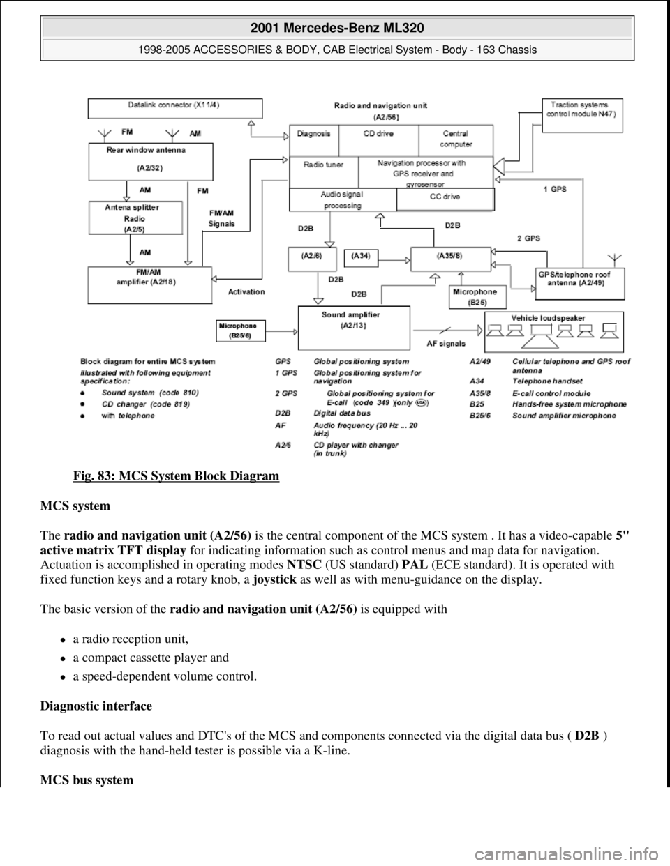
Fig. 83: MCS System Block Diagram
MCS system
The radio and navigation unit (A2/56) is the central component of the MCS system . It has a video-capable 5"
active matrix TFT display for indicating information such as control menus and map data for navigation.
Actuation is accomplished in operating modes NTSC (US standard) PAL (ECE standard). It is operated with
fixed function keys and a rotary knob, a joystick as well as with menu-guidance on the display.
The basic version of the radio and navigation unit (A2/56) is equipped with
a radio reception unit,
a compact cassette player and
a speed-dependent volume control.
Diagnostic interface
To read out actual values and DTC's of the MCS and components connected via the digital data bus ( D2B )
diagnosis with the hand-held tester is possible via a K-line.
MCS bus system
2001 Mercedes-Benz ML320
1998-2005 ACCESSORIES & BODY, CAB Electrical System - Body - 163 Chassis
me
Saturday, October 02, 2010 3:30:06 PMPage 131 © 2006 Mitchell Repair Information Company, LLC.