1997 MERCEDES-BENZ ML430 fuel
[x] Cancel search: fuelPage 2229 of 4133

AR47.10-P-4000GH
Empty fuel tank if fuel pump is faulty
28.10.97
MODEL
163.113 with ENGINE 612.963
MODEL
163.128 with ENGINE 628.963
MODEL
163.136 with ENGINE 111.977
MODEL
163.154 with ENGINE 112.942
MODEL
163.157 with ENGINE 112.970
MODEL
163.172 with ENGINE 113.942
MODEL
163.174 with ENGINE 113.981
MODEL
163.175 with ENGINE 113.965
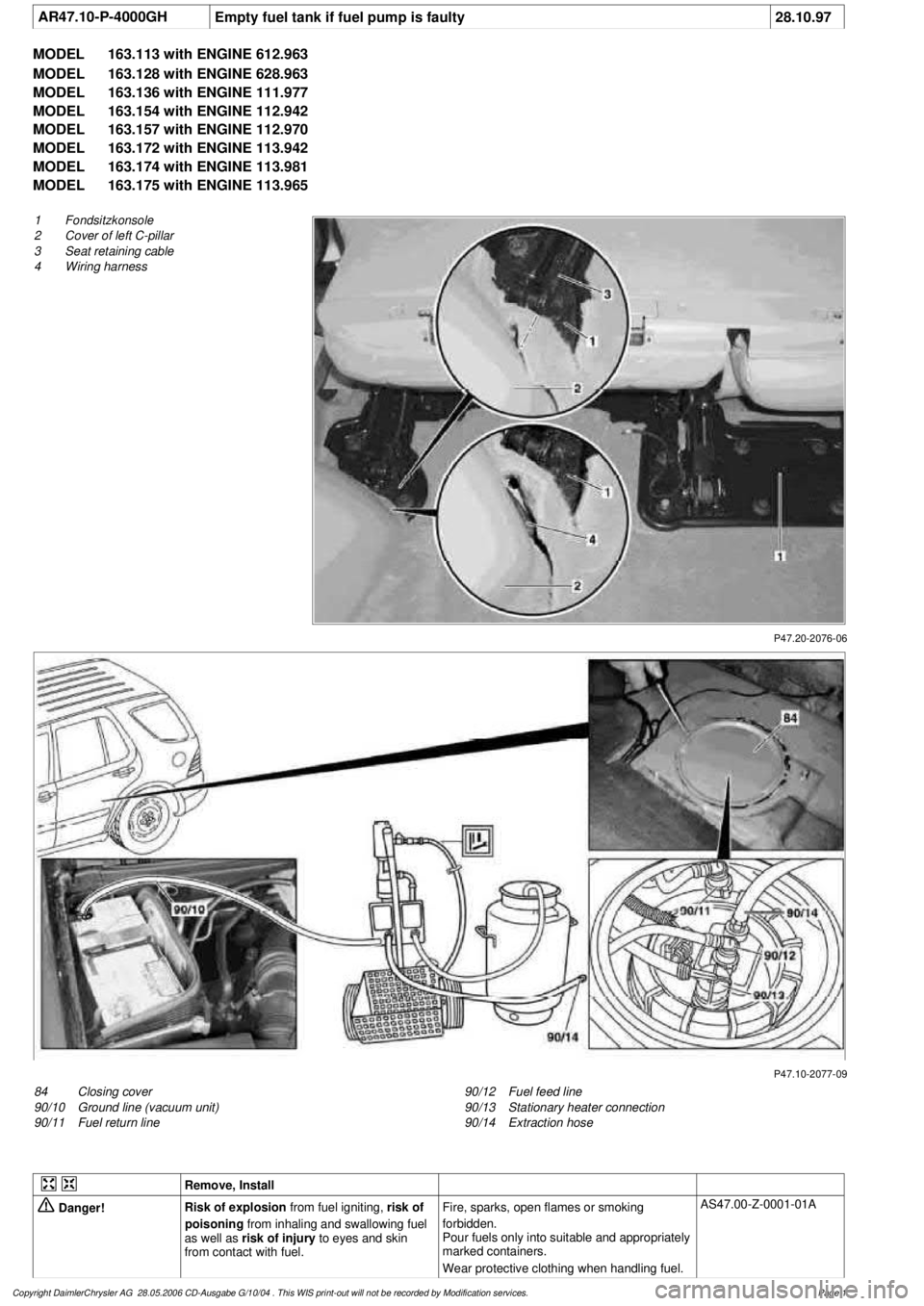
P47.20-2076-06
1
Fondsitzkonsole
2
Cover of left C-pillar
3
Seat retaining cable
4
Wiring harness
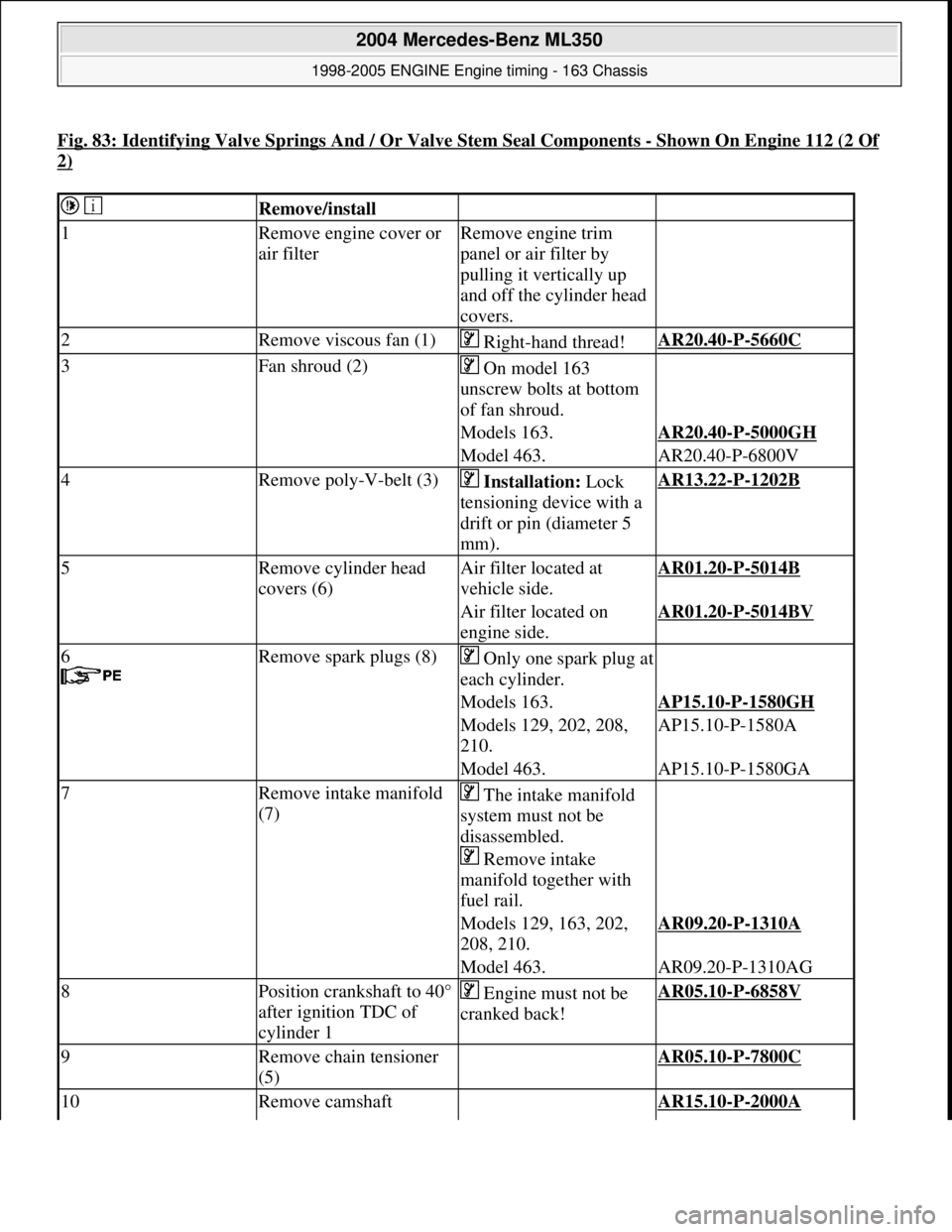
P47.10-2077-09
84
Closing cover
90/10
Ground line (vacuum unit)
90/11
Fuel return line
90/12
Fuel feed line
90/13
Stationary heater connection
90/14
Extraction hose
Remove, Install
Danger!
Risk of explosion
from fuel igniting,
risk of
poisoning
from inhaling and swallowing fuel
as well as
risk of injury
to eyes and skin
from contact with fuel.
Fire, sparks, open flames or smoking
forbidden.
Pour fuels only into suitable and appropriately
marked containers.
Wear protective clothing when handling fuel.
AS47.00-Z-0001-01A
Copyright DaimlerChrysler AG 28.05.2006 CD-Ausgabe G/10/04 . This WIS print-out will not be recorde
d by Modification services.
Page 1
Page 2230 of 4133

1.1
Unscrew bolts at rear of 2/3 seat bench and
raise rear of seat bench
Up to VIN A145272, X708318.
1.2
Remove covers at seat frame of 60% bench
seat
As of VIN A145273, X708319.
AR91.12-P-1100GH
Only remove the covers which are
identified in the document with A, D and E.
2.1
Fold 60% bench seat forward into footwell
As of VIN A145273, X708319. See
operator's manual.
3.1
Pull floor covering below rear seat mounting
bracket (1) of 60% seat forward
Carefully pull floor covering forward under
the seat console to prevent it from tearing.
As of VIN A145273, X708319.
4.1
Pull the floor covering forward under the front
corner of the left C-pillar cover (2)
Carefully pull the floor covering forward
under the cover to prevent it from tearing.
As of VIN A145273, X708319.
5
Cut into floor covering directly behind seat
retaining cable (3)
Ensure that the wiring harness (4) is not
damaged when cutting the floor covering.
As of VIN A145273, X708319. Broken
line marks the cut.
6
Fold floor mat back
Do not crease floor mat!
Fold floor mat back far enough to provide
access to cap (84) between body and fuel
pump.
7
Remove end cover (84) of body
Installation:
Replace cap and insert with
new sealing compound.
Cap (84) is sealed in with body sealer.
Heat with hot air blower to make it easier to
remove.
8
Seal fuel return line (90/11)
Pliers
*163589003700
9
Connect extraction hose (90/14) with adapter
hose to connection for fuel return line (90/11)
Extraction hose
*168589009000
Adapter hose
*163589009100
10
Connect ground cable (90/10) of extraction
pump ground terminal vehicle battery
Pumping out
11
Pump fuel out into safety container using
extraction pump
*BF47.10-P-1001-01A
*WH58.30-Z-1001-16A
12
Install in the reverse order
Fuel tank
Number
Designation
Models
163.113/
136/154/
172 up to
31.08.01
Models
163.113/
136/154/
172 as of
01.09.01
Models
163.157/
175
Model
163.128
Model
163.174
BF47.10-P-1001-01A
Fuel tank capacity
Total capacity
Liter
72838393
Reserve capacity
Liter
10121212
Copyright DaimlerChrysler AG 28.05.2006 CD-Ausgabe G/10/04 . This WIS print-out will not be recorde
d by Modification services.
Page 2
Page 2232 of 4133

AP18.00-P-0101AR
Engine - oil and filter change
20.1.99
ENGINE
612
Modification notes
12.9.02
Engine oil level modified
Step 9:
Only Model 203:
Up to engine end number: 134 163 oil level
MAX. 135
mm,
MIN 110
mm.
As of engine end number: 134 164 oil level
MAX. 124,5
mm,
MIN 99,5
mm.
Remove
Danger!
Risk of death
cased by vehicle slipping or
toppling off of the lifting platform.
Align vehicle between the columns of the
hydraulic hoist and position the four support
plates below the hoist support points specified
by the vehicle manufacturer.
AS00.00-Z-0010-01A
Danger!
Risk of accident
caused by vehicle starting
off by itself when engine is running.
Risk of
injury
caused by contusions and burns when
working in engine during starting procedure
Secure vehicle to prevent it from moving.
Wear closed and snug-fitting work clothes.
Do not grasp hot or rotating parts.
AS00.00-Z-0005-01A
Change the engine oil only when the engine
is at operating temperature
1
Remove trim panel of cylinder head cover
AR01.20-P-5014-02B
2
Replace oil filter element, drain oil filter
Model 203: Remove clamp attaching fuel
line in order to insert wrench socket.
AP18.00-P-0101-06EG
*BA18.20-P-1002-01G
Socket wrench bit
*103589020900
3.1
Suction off engine oil
AP18.00-P-0101-02Z
4.1
Remove rear left frame cross brace
Only necessary when draining engine oil
at oil drain plug.
MODEL 163
f
Model 203 except 203.018/218/718, 209
AR94.30-P-5300P
Model 210
AR94.30-P-5300AB
4.2
Detach lower engine compartment paneling
Only necessary when draining engine oil
at oil drain plug.
f
Only Model 203.018/218/718
AR61.20-P-1105P
5.1
Unscrew oil drain plug, drain engine oil
Install
6.1
Screw in oil drain plug
Replace sealing ring, in order to avoid
leakage.
*BA01.45-P-1003-01A
7
Pour in engine oil
Note specified and approved quality
grades and viscosity classes conforming to
SAE at enduring ambient temperatures.
*BE18.00-P-1001-02B
*BF18.00-P-1001-01A
g
Viscosity classes of engine oils (car engines)
Sheet 224.1
BB00.40-P-0224-01A
8
Run engine and inspect for leaks
9
Switch off engine
10.1
Fit on bottom part of noise encapsulation
Only necessary when draining engine oil
at oil drain plug.
f
Model 210
AR94.30-P-5300AB
MODEL 203, 209
AR94.30-P-5300P
MODEL 163
10.2
Install lower engine compartment paneling.
Only necessary when draining engine oil
at oil drain plug.
f
Only Model 203.018/218/718
AR61.20-P-1105P
Copyright DaimlerChrysler AG 20.05.2006 CD-Ausgabe G/10/04 . This WIS print-out will not be recorde
d by Modification services.
Page 1
Page 2239 of 4133

AF07.00-P-9000B
Engine runs rough, surges or does not turn over
29.4.02
ENGINE
611 in MODEL 203, 202, 210
ENGINE
612 in MODEL 163, 203, 210, 209
ENGINE
613 in MODEL 210, 220
ENGINE
628 in MODEL 163, 220, 211
ENGINE
646 in MODEL 203, 211
ENGINE
647 in MODEL 211
ENGINE
648 in MODEL 220, 211
ENGINE
668 in MODEL 168
ENGINE
612, 628 in MODEL 463
Modification notes
23.3.01
Supersedes STIP 07.16-014 dated 11.12.00
Damage code
Cause
Remedy
07 206 D5
High-pressure pump
To verify whether high pressure pump is
damaged.
#
High pressure pump of common rail
injection system is damaged mechanically.
1
Remove/install/replace high pressure
pump.
When the high pressure pump of the common
rail injection system is damaged metal chips
and/or damage to the pump drive (timing
drive) can occur due to contamination of the
injection system components.
2
Turn high pressure pump by hand with
driver.
If mechanical resistance can be felt,
perform the following tests. Clarify additional
work with ESKULAB by specifying repair work:
#
3
Check driver of high pressure pump or
mount in sprocket for damage (visual
check).
If high pressure pump is locked:
#
4
Check timing
5
Check timing drive for damage.
In each case:
#
6
Remove/install/replace timing chain.
If timing deviates by a crankshaft angle of
more than 20 degrees (corresponding to one
tooth skipped):
#
7
Check pressure loss.
8
Open low pressure connection on high
pressure pump return (plastic line in
area of pressure regulator valve) and
check connection point in rail for chips.
If chips are present when checking
injection system:
#
9
Thoroughly clean all fuel low pressure
lines as well as feed and return lines.
Flush and blow out with compressed air.
10
Remove fuel preheater and fuel filter
with filter housing, replace.
Fuel preheater is only installed in models
202, 203 and 163.
11
Remove/install/replace fuel cooler at
vehicle and engine end.
Not installed in model 210 up to 6/99 and
model 168.
12
Remove fuel tank, replace.
On engine 628:
#
13
Remove/install/replace electric supply
pump.
14
Remove/install/replace injectors, rail
(including pressure regulation valve and
rail pressure sensor), high pressure
lines and injector leak oil rail.*
Copyright DaimlerChrysler AG 28.05.2006 CD-Ausgabe G/10/04 . This WIS print-out will not be recorde
d by Modification services.
Page 1
Page 2240 of 4133

Fuel pump (gear pump) and electric
shutoff valve can remain on engine.
15
Check injection system for leakage.
16
Check with HHT/DAS for proper
function (check actual value).
17
Read DTC memory and erase after
checking.
Copyright DaimlerChrysler AG 28.05.2006 CD-Ausgabe G/10/04 . This WIS print-out will not be recorde
d by Modification services.
Page 2
Page 2320 of 4133

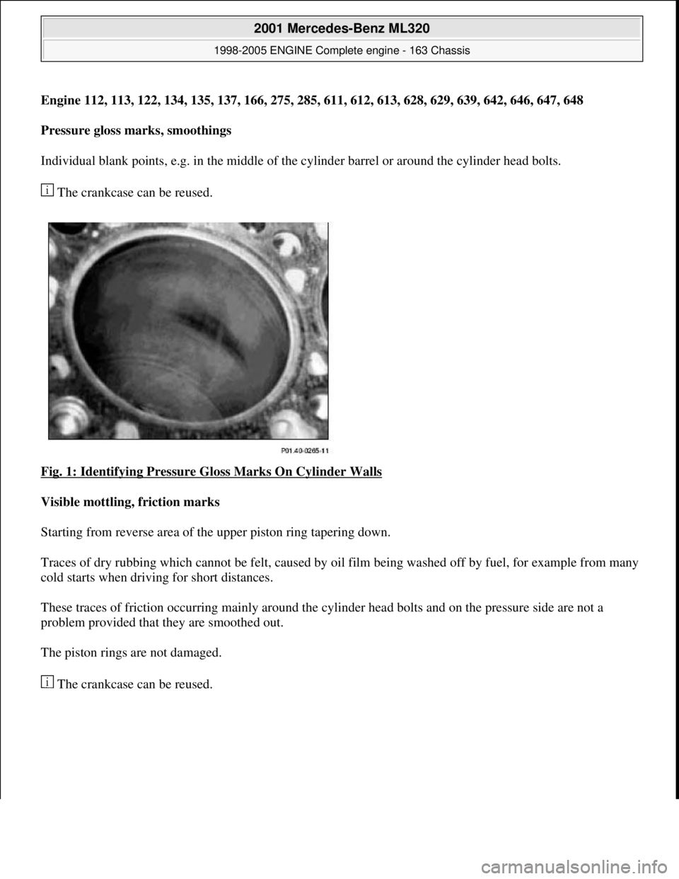
Fig. 83: Identifying Valve Springs And / Or Valve Stem Seal Components -Shown On Engine 112 (2 Of
2)
Remove/install
1Remove engine cover or
air filterRemove engine trim
panel or air filter by
pulling it vertically up
and off the cylinder head
covers.
2Remove viscous fan (1) Right-hand thread!AR20.40-P-5660C
3Fan shroud (2) On model 163
unscrew bolts at bottom
of fan shroud.
Models 163.AR20.40-P-5000GH
Model 463.AR20.40-P-6800V
4Remove poly-V-belt (3) Installation: Lock
tensioning device with a
drift or pin (diameter 5
mm).AR13.22-P-1202B
5Remove cylinder head
covers (6)Air filter located at
vehicle side.AR01.20-P-5014B
Air filter located on
engine side.AR01.20-P-5014BV
6
Remove spark plugs (8)Only one spark plug at
each cylinder.
Models 163.AP15.10-P-1580GH
Models 129, 202, 208,
210.AP15.10-P-1580A
Model 463.AP15.10-P-1580GA
7Remove intake manifold
(7) The intake manifold
system must not be
disassembled.
Remove intake
manifold together with
fuel rail.
Models 129, 163, 202,
208, 210.AR09.20-P-1310A
Model 463.AR09.20-P-1310AG
8Position crankshaft to 40°
after ignition TDC of
cylinder 1 Engine must not be
cranked back!AR05.10-P-6858V
9Remove chain tensioner
(5) AR05.10-P-7800C
10Remove camshaft AR15.10-P-2000A
2004 Mercedes-Benz ML350
1998-2005 ENGINE Engine timing - 163 Chassis
me
Saturday, October 02, 2010 3:39:38 PMPage 79 © 2006 Mitchell Repair Information Company, LLC.
Page 2357 of 4133

Engine 112, 113, 122, 134, 135, 137, 166, 275, 285, 611, 612, 613, 628, 629, 639, 642, 646, 647, 648
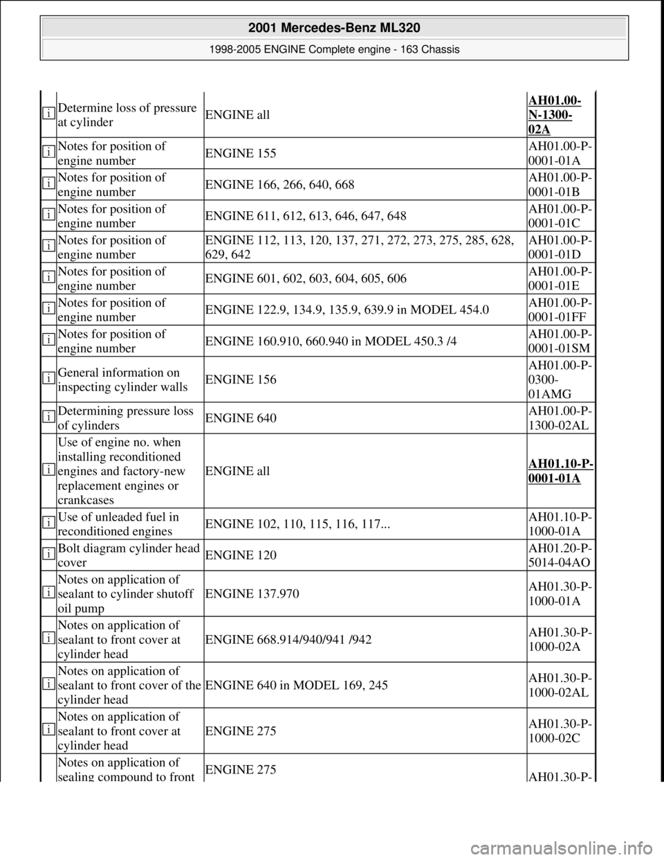
Pressure gloss marks, smoothings
Individual blank points, e.g. in the middle of th e cylinder barrel or around the cylinder head bolts.
The crankcase can be reused.
Fig. 1: Identifying Pressure Gloss Marks On Cylinder Walls
Visible mottling, friction marks
Starting from reverse area of th e upper piston ring tapering down.
Traces of dry rubbing which cannot be felt, caused by oi l film being washed off by fuel, for example from many
cold starts when driving for short distances.
These traces of friction occurring mainly around the cy linder head bolts and on the pressure side are not a
problem provided that they are smoothed out.
The piston rings are not damaged.
The crankcase can be reused.
2001 Mercedes-Benz ML320
1998-2005 ENGINE Complete engine - 163 Chassis
me
Saturday, October 02, 2010 3:17:55 PMPage 2 © 2006 Mitchell Repair Information Company, LLC.
Page 2363 of 4133

Determine loss of pressure
at cylinderENGINE all
AH01.00-
N-1300-
02A
Notes for position of
engine numberENGINE 155AH01.00-P-
0001-01A
Notes for position of
engine numberENGINE 166, 266, 640, 668AH01.00-P-
0001-01B
Notes for position of
engine numberENGINE 611, 612, 613, 646, 647, 648AH01.00-P-
0001-01C
Notes for position of
engine numberENGINE 112, 113, 120, 137, 271, 272, 273, 275, 285, 628,
629, 642AH01.00-P-
0001-01D
Notes for position of
engine numberENGINE 601, 602, 603, 604, 605, 606AH01.00-P-
0001-01E
Notes for position of
engine numberENGINE 122.9, 134.9, 135.9, 639.9 in MODEL 454.0AH01.00-P-
0001-01FF
Notes for position of
engine numberENGINE 160.910, 660.940 in MODEL 450.3 /4AH01.00-P-
0001-01SM
General information on
inspecting cylinder wallsENGINE 156
AH01.00-P-
0300-
01AMG
Determining pressure loss
of cylindersENGINE 640AH01.00-P-
1300-02AL
Use of engine no. when
installing reconditioned
engines and factory-new
replacement engines or
crankcases
ENGINE allAH01.10-P-
0001-01A
Use of unleaded fuel in
reconditioned enginesENGINE 102, 110, 115, 116, 117...AH01.10-P-
1000-01A
Bolt diagram cylinder head
coverENGINE 120AH01.20-P-
5014-04AO
Notes on application of
sealant to cylinder shutoff
oil pump
ENGINE 137.970AH01.30-P-
1000-01A
Notes on application of
sealant to front cover at
cylinder head
ENGINE 668.914/940/941 /942AH01.30-P-
1000-02A
Notes on application of
sealant to front cover of the
cylinder head
ENGINE 640 in MODEL 169, 245AH01.30-P-
1000-02AL
Notes on application of
sealant to front cover at
cylinder head
ENGINE 275AH01.30-P-
1000-02C
Notes on application of
sealing compound to front ENGINE 275AH01.30-P-
2001 Mercedes-Benz ML320
1998-2005 ENGINE Complete engine - 163 Chassis
me
Saturday, October 02, 2010 3:17:55 PMPage 7 © 2006 Mitchell Repair Information Company, LLC.