1997 MERCEDES-BENZ ML430 fuel
[x] Cancel search: fuelPage 2042 of 4133

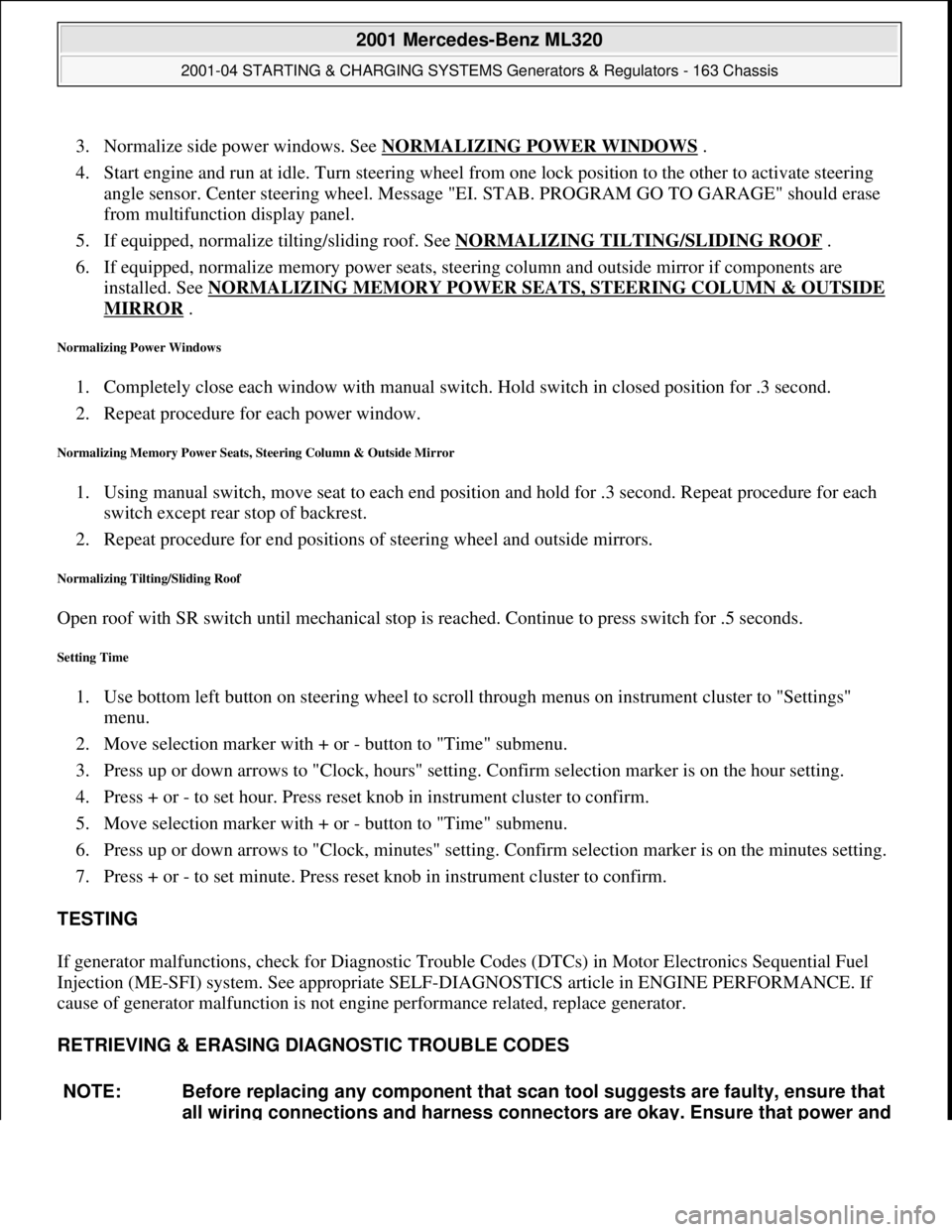
3. Normalize side power windows. See NORMALIZING POWER WINDOWS .
4. Start engine and run at idle. Turn steering wheel from one lock position to the other to activate steering
angle sensor. Center steering wheel. Message "EI. STAB. PROGRAM GO TO GARAGE" should erase
from multifunction display panel.
5. If equipped, normalize tilting/sliding roof. See NORMALIZING TILTING/SLIDING ROOF
.
6. If equipped, normalize memory power seats, steering column and outside mirror if components are
installed. See NORMALIZING MEMORY POWER SEATS, STEERING COLUMN & OUTSIDE
MIRROR .
Normalizing Power Windows
1. Completely close each window with manual switch. Hold switch in closed position for .3 second.
2. Repeat procedure for each power window.
Normalizing Memory Power Seats, Steering Column & Outside Mirror
1. Using manual switch, move seat to each end position and hold for .3 second. Repeat procedure for each
switch except rear stop of backrest.
2. Repeat procedure for end positions of steering wheel and outside mirrors.
Normalizing Tilting/Sliding Roof
Open roof with SR switch until mechanical stop is reached. Continue to press switch for .5 seconds.
Setting Time
1. Use bottom left button on steering wheel to scroll through menus on instrument cluster to "Settings"
menu.
2. Move selection marker with + or - button to "Time" submenu.
3. Press up or down arrows to "Clock, hours" setting. Confirm selection marker is on the hour setting.
4. Press + or - to set hour. Press reset knob in instrument cluster to confirm.
5. Move selection marker with + or - button to "Time" submenu.
6. Press up or down arrows to "Clock, minutes" setting. Confirm selection marker is on the minutes setting.
7. Press + or - to set minute. Press reset knob in instrument cluster to confirm.
TESTING
If generator malfunctions, check for Diagnostic Trouble Codes (DTCs) in Motor Electronics Sequential Fuel
Injection (ME-SFI) system. See appropriate SELF-DIAGNOSTICS article in ENGINE PERFORMANCE. If
cause of generator malfunction is not engine performance related, replace generator.
RETRIEVING & ERASING DIAGNOSTIC TROUBLE CODES
NOTE: Before replacing any component that scan tool suggests are faulty, ensure that
all wiring connections and harness connectors are okay. Ensure that power and
2001 Mercedes-Benz ML320
2001-04 STARTING & CHARGING SYSTEMS Generators & Regulators - 163 Chassis
me
Saturday, October 02, 2010 3:20:32 PMPage 8 © 2006 Mitchell Repair Information Company, LLC.
Page 2087 of 4133

8
Attach guard plate for radiator/condenser
y
Guard plate for radiator/condenser
Engine 606 in model 124,
Engine 606.961 in model 140,
Engine 112, 113, 604, 605, 611.960 in model
202,
Engine 602.983, 612.966 in model 461,
Engine 628.962, 612.965, 606.964, 112.945,
113.962/ 982 in model 463,
Engine 111, 112, 611.962, 612.962 in model
203,
Engine 112, 113, 611.961, 612.961, 613.961
in model 210,
Engine 112 in model 170,
Engine 112 in model 220,
Engine 113 in model 211, 215, 220,
Engine 112 in model 208,
Engine 112, 113, 612.963, 628.963 in model
163,
Engine 112.923 /943, 113.961 in model 129,
Engine 137, 275 in model 215, 220,
Engine 613.960, 628.960 in model 220,
Engine 113.992 in model 230.474,
Engine 271 in model 209, 203,
Engine 285.950 in model 240.078 /178,
Engine 612.967 in model 209.316,
Engine 648 in model 220
Engine 112.951 in model 639.601/603/ 605/
701 /703 /705 /801 /803 /805
Engine 646.983 /984 in model 639.601/
603 /605 /701 /703 /705 /801 /803 /805
Engine 646.982 in model 639.601/ 603/ 605/
701 /703 /705
WF58.50-P-0110-01A
9
Remove air cleaner housing (5)
10
Remove air intake pipe (6) with resonance
tube (7)
Separate connector of hot film mass air
flow sensor (HFM) for this step and unbolt air
intake pipe at cylinder head cover
The air intake pipe is attached at the rear
at the intake manifold with a plastic plate.
Do not damage the plastic strap.
Engine 112.942/ 970
AR07.07-P-1454A
Engine 113.942/ 965/ 981
AR07.07-P-1454MV
Danger!
Risk of explosion
caused by fuel igniting,
risk of poisoning
caused by inhaling and
swallowing fuel as well as
risk of injury
to
eyes and skin caused by contact with fuel.
No fire, sparks, open flames or smoking.
Pour fuels only into suitable and appropriately
marked containers.
Wear protective clothing when handling fuel.
AS47.00-Z-0001-01A
11
Disconnect fuel line at fuel rail
Release fuel pressure at service valve!
Collect fuel!
Engine 112:
#
*BA07.52-P-1001-01A
Engine 113:
#
*BA07.52-P-1001-01A
Pressure hose
*119589046300
12
Remove right and left ignition coils (12)
AR15.12-P-2003A
13
Remove right and left cylinder head covers (13)
AR01.20-P-5014B
14
Remove the intake manifold (14)
Installation:
On vehicles with engine
damage, the intake manifold must be
examined for swarfs before assembling and
any swarfs present must be removed, in order
to avoid consequential damage.
AR09.20-P-1310A
The intake manifold system must not be
disassembled.
Remove intake manifold with fuel distributor
15.1
Remove camshaft position sensor (15)
Only necessary if the right cylinder head is
removed.
AR15.10-P-2000A
Copyright DaimlerChrysler AG 20.05.2006 CD-Ausgabe G/10/04 . This WIS print-out will not be recorde
d by Modification services.
Page 3
Page 2090 of 4133

Fig., see
AR01.30-P-5800-03BAR01.30-P-5800-03B
Cylinder head
Number
Designation
Engine
112.910/911/912/
913/914/915/
916/917/920/
921/922/923/
940/941/942/
943/944/945/
946/947/949/
951/953/954/
955/960/961/
970/972/973/975
Engine
113.940/941/
942/943/944/
948/960/961/
962/963/965/
966/967/968/
969/980/981/
982/984/986/
992
BA01.30-P-1001-01D
Bolt of cylinder head to
crankcase
1st stageNm
1010
2nd stage
Nm
3030
3rd stage
(°
9090
4th stage
(°
9090
Crankcase, timing case cover, end cover
Number
Designation
Engine
112
except
112.951
Engine
113.940/941/
942/943/944/
945/946/948/
960/961/962/
963/965/966/
967/968/969/
980/981/982/
984/986/992
BA01.40-P-1002-01C
Bolt, cylinder head to timing case cover
Nm
2020
Camshaft
Number
Designation
Engine
112
except 112.951
Engine
113.940/941/
942/943/944/
948/961/962/
963/965/966/
967/968/969/
980/981/982/
984/986/992
BA05.20-P-1001-01B
Bolt of camshaft sprocket
M12 x 45
1st stageNm
5050
2nd stage
(°
9090
Fuel rail
Number
Designation
Engine
112 except
112.945/951/
960/961
BA07.52-P-1001-01A
Fuel feed line to fuel rail
Nm
38
Copyright DaimlerChrysler AG 20.05.2006 CD-Ausgabe G/10/04 . This WIS print-out will not be recorde
d by Modification services.
Page 6
Page 2091 of 4133

Fuel rail
Number
Designation
Engine
113.940/941/
942/943/944/
945/946/948/
960/961/962/
963/965/966/
967/968/969/
980/981/982/
984/986/988/
BA07.52-P-1001-01A
Fuel feed line to fuel distributor
Nm
38
Exhaust manifold
Number
Designation
Engine
112
except
112.951
Engine
113.940/941/
942/943/944/
945/946/948/
960/961/962/
963/965/966/
967/968/969/
980/981/982/
984/986/992/
993
BA14.10-P-1002-01B
Flange connection of exhaust manifold or front
exhaust pipes
Nm
2020
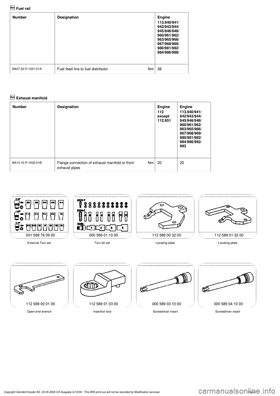
112 589 00 32 00 112 589 01 32 00
001 589 76 09 00 000 589 01 10 00
Locating plate
Torx bit set
External Torx set
Locating plate
112 589 01 03 00
Screwdriver insert
Insertion tool
Open-end wrench
Screwdriver insert
112 589 00 01 00000 589 03 10 00000 589 04 10 00
Copyright DaimlerChrysler AG 20.05.2006 CD-Ausgabe G/10/04 . This WIS print-out will not be recorde
d by Modification services.
Page 7
Page 2095 of 4133

8
Attach guard plate for radiator/condenser
y
Guard plate for radiator/condenser
Engine 606 in model 124,
Engine 606.961 in model 140,
Engine 112, 113, 604, 605, 611.960 in model
202,
Engine 602.983, 612.966 in model 461,
Engine 628.962, 612.965, 606.964, 112.945,
113.962/ 982 in model 463,
Engine 111, 112, 611.962, 612.962 in model
203,
Engine 112, 113, 611.961, 612.961, 613.961
in model 210,
Engine 112 in model 170,
Engine 112 in model 220,
Engine 113 in model 211, 215, 220,
Engine 112 in model 208,
Engine 112, 113, 612.963, 628.963 in model
163,
Engine 112.923 /943, 113.961 in model 129,
Engine 137, 275 in model 215, 220,
Engine 613.960, 628.960 in model 220,
Engine 113.992 in model 230.474,
Engine 271 in model 209, 203,
Engine 285.950 in model 240.078 /178,
Engine 612.967 in model 209.316,
Engine 648 in model 220
Engine 112.951 in model 639.601/603/ 605/
701 /703 /705 /801 /803 /805
Engine 646.983 /984 in model 639.601/
603 /605 /701 /703 /705 /801 /803 /805
Engine 646.982 in model 639.601/ 603/ 605/
701 /703 /705
WF58.50-P-0110-01A
9
Remove air cleaner housing (5)
10
Remove air intake pipe (6) with resonance
tube (7)
Separate connector of hot film mass air
flow sensor (HFM) for this step and unbolt air
intake pipe at cylinder head cover
The air intake pipe is attached at the rear
at the intake manifold with a plastic plate.
Do not damage the plastic strap.
Engine 112.942/ 970
AR07.07-P-1454A
Engine 113.942/ 965/ 981
AR07.07-P-1454MV
Danger!
Risk of explosion
caused by fuel igniting,
risk of poisoning
caused by inhaling and
swallowing fuel as well as
risk of injury
to
eyes and skin caused by contact with fuel.
No fire, sparks, open flames or smoking.
Pour fuels only into suitable and appropriately
marked containers.
Wear protective clothing when handling fuel.
AS47.00-Z-0001-01A
11
Disconnect fuel line at fuel rail
Release fuel pressure at service valve!
Collect fuel!
Engine 112:
#
*BA07.52-P-1001-01A
Engine 113:
#
*BA07.52-P-1001-01A
Pressure hose
*119589046300
12
Remove right and left ignition coils (12)
AR15.12-P-2003A
13
Remove right and left cylinder head covers (13)
AR01.20-P-5014B
14
Remove the intake manifold (14)
Installation:
On vehicles with engine
damage, the intake manifold must be
examined for swarfs before assembling and
any swarfs present must be removed, in order
to avoid consequential damage.
AR09.20-P-1310A
The intake manifold system must not be
disassembled.
Remove intake manifold with fuel distributor
15.1
Remove camshaft position sensor (15)
Only necessary if the right cylinder head is
removed.
AR15.10-P-2000A
Copyright DaimlerChrysler AG 20.05.2006 CD-Ausgabe G/10/04 . This WIS print-out will not be recorde
d by Modification services.
Page 3
Page 2098 of 4133

Fig., see
AR01.30-P-5800-03BAR01.30-P-5800-03B
Cylinder head
Number
Designation
Engine
112.910/911/912/
913/914/915/
916/917/920/
921/922/923/
940/941/942/
943/944/945/
946/947/949/
951/953/954/
955/960/961/
970/972/973/975
Engine
113.940/941/
942/943/944/
948/960/961/
962/963/965/
966/967/968/
969/980/981/
982/984/986/
992
BA01.30-P-1001-01D
Bolt of cylinder head to
crankcase
1st stageNm
1010
2nd stage
Nm
3030
3rd stage
(°
9090
4th stage
(°
9090
Crankcase, timing case cover, end cover
Number
Designation
Engine
112
except
112.951
Engine
113.940/941/
942/943/944/
945/946/948/
960/961/962/
963/965/966/
967/968/969/
980/981/982/
984/986/992
BA01.40-P-1002-01C
Bolt, cylinder head to timing case cover
Nm
2020
Camshaft
Number
Designation
Engine
112
except 112.951
Engine
113.940/941/
942/943/944/
948/961/962/
963/965/966/
967/968/969/
980/981/982/
984/986/992
BA05.20-P-1001-01B
Bolt of camshaft sprocket
M12 x 45
1st stageNm
5050
2nd stage
(°
9090
Fuel rail
Number
Designation
Engine
112 except
112.945/951/
960/961
BA07.52-P-1001-01A
Fuel feed line to fuel rail
Nm
38
Copyright DaimlerChrysler AG 20.05.2006 CD-Ausgabe G/10/04 . This WIS print-out will not be recorde
d by Modification services.
Page 6
Page 2099 of 4133

Fuel rail
Number
Designation
Engine
113.940/941/
942/943/944/
945/946/948/
960/961/962/
963/965/966/
967/968/969/
980/981/982/
984/986/988/
BA07.52-P-1001-01A
Fuel feed line to fuel distributor
Nm
38
Exhaust manifold
Number
Designation
Engine
112
except
112.951
Engine
113.940/941/
942/943/944/
945/946/948/
960/961/962/
963/965/966/
967/968/969/
980/981/982/
984/986/992/
993
BA14.10-P-1002-01B
Flange connection of exhaust manifold or front
exhaust pipes
Nm
2020
112 589 00 32 00 112 589 01 32 00
001 589 76 09 00 000 589 01 10 00
Locating plate
Torx bit set
External Torx set
Locating plate
112 589 01 03 00
Screwdriver insert
Insertion tool
Open-end wrench
Screwdriver insert
112 589 00 01 00000 589 03 10 00000 589 04 10 00
Copyright DaimlerChrysler AG 20.05.2006 CD-Ausgabe G/10/04 . This WIS print-out will not be recorde
d by Modification services.
Page 7
Page 2105 of 4133

GF54.30-P-2002A
Display instruments, location / task / function
24.10.96
MODEL
129, 140 as of 1.6.96,
163, 168, 170,
202 as of 1.8.96,
208 up to 31.7.99,
210 as of 1.6.96 up to 30.6.99
Display
Type of data transmission
D
Outside temperature indicator (A1p4)
D
Fuel level gauge (A1p2)
D
Engine oil pressure gauge (A1p3), only
model 129 and model 140
D
Low windshield washer fluid level
indicator lamp (A1e13), model 163 as of
01.09.01
Direct lines
GF54.30-P-3004A
D
Total mileage odometer (A1h4)
D
Electronic speedometer (A1p8)
D
Tachometer (A1p5)
D
Coolant temperature gauge (A1p1)
D
Active service system (ASSYST)
D
Gear indicator (A1p12), only model 168
CAN data lines
GF54.30-P-3005A
D
Electronic clock
Internal
GF54.30-P-3011A
Copyright DaimlerChrysler AG 04.06.2006 CD-Ausgabe G/10/04 . This WIS print-out will not be recorde
d by Modification services.
Page 1