Page 851 of 4133
47 Getting started
Driving
Starting difficulties
If the engine does not start as described,
carry out the following steps:�
Turn key in starter to position0 and re-
peat starting procedure.
Remember that extended starting at-
tempts can drain the battery.
�
Get a jump start (
�page 281).
If the engine does not start after several
starting attempts, there could be a mal-
function in the engine electronics or in the
fuel supply system.
�
Notify an authorized Mercedes-Benz
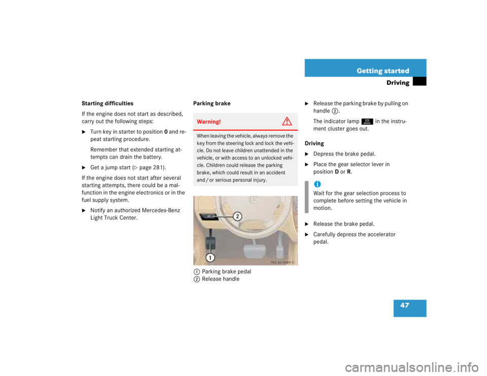
Light Truck Center.Parking brake
1Parking brake pedal
2Release handle
�
Release the parking brake by pulling on
handle2.
The indicator lampÉ in the instru-
ment cluster goes out.
Driving
�
Depress the brake pedal.
�
Place the gear selector lever in
positionD orR.
�
Release the brake pedal.
�
Carefully depress the accelerator
pedal.
Warning!
G
When leaving the vehicle, always remove the
key from the steering lock and lock the vehi-
cle. Do not leave children unattended in the
vehicle, or with access to an unlocked vehi-
cle. Children could release the parking
brake, which could result in an accident
and / or serious personal injury.
iWait for the gear selection process to
complete before setting the vehicle in
motion.
Page 856 of 4133
52 Getting startedDrivingThe coolant temperature is over 248°F
(120°C)
The coolant is too hot and is no longer
cooling the engine.�
Stop the vehicle as soon as possible
and turn off the engine. Allow engine
and coolant to cool.
�
Check the coolant level and add cool-
ant if necessary (
�page 222).In case of accident
If the vehicle is leaking gasoline:
�
Do not start the engine under any cir-
cumstances.
�
Notify local fire and / or police authori-
ties.
If the extent of the damage cannot be de-
termined:
�
Notify an authorized Mercedes-Benz
Light Truck Center.
If no damage can be determined on the
�
major assemblies
�
fuel system
�
engine mount:
�
Start the engine in the usual manner.
Page 892 of 4133
88 Controls in detailLocking and unlocking
�In the “Controls in detail” section you will
find detailed information on how to ope-
rate the equipment installed in your vehi-
cle. If you are already familiar with the ba-
sic functions of your vehicle, this section
will be of particular interest to you.
To quickly familiarize yourself with the ba-
sic functions of the vehicle, refer to the
“Getting started” section of this manual.
The corresponding page numbers are
given at the beginning of each segment.
Locking and unlocking
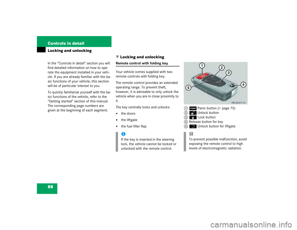
Remote control with folding key
Your vehicle comes supplied with two
remote controls with folding key.
The remote control provides an extended
operating range. To prevent theft,
however, it is advisable to only unlock the
vehicle when you are in close proximity to
it.
The key centrally locks and unlocks:�
the doors
�
the liftgate
�
the fuel filler flap1ÂPanic button (
�page 75)
2ŒUnlock button
3‹Lock button
4Release button for key
5ŠUnlock button for liftgate
iIf the key is inserted in the steering
lock, the vehicle cannot be locked or
unlocked with the remote control.
!To prevent possible malfunction, avoid
exposing the remote control to high
levels of electromagnetic radiation.
Page 893 of 4133
89 Controls in detail
Locking and unlocking
Unlocking
Unlocking the driver’s door and fuel
filler flap�
Press buttonΠonce.
All turn signal lamps flash once to indi-
cate that the driver’s door and the fuel
filler flap are unlocked.Global unlocking
�
Press buttonΠtwice.
All turn signal lamps flash once to indi-
cate that all doors, fuel filler flap and
liftgate are unlocked.
Unlocking the liftgate
�
Press buttonŠ.
Only the liftgate unlocks.
Locking
�
Press button‹ once.
All turn signal lamps flash three times
to indicate that all doors, the liftgate
and the fuel filler flap are locked.
iUnlocking the vehicle with the remote
control deactivates the anti-theft
alarm.
The vehicle will lock again automatical-
ly and reactivate the anti-theft system
within approximately 40 seconds of un-
locking if neither door nor liftgate is
opened.
iLocking the vehicle with the remote
control activates the anti-theft alarm.
iIf the turn signal lamps do not flash
three times, one of the following ele-
ments may not be properly closed:�
a door
�
the liftgate
�
the hood
Close the respective element and lock
the vehicle again.
Warning!
G
When leaving the vehicle, always remove the
key from the steering lock, and lock your ve-
hicle. Do not leave children unattended in
the vehicle, or with access to an unlocked
vehicle. Unsupervised use of vehicle equip-
ment may cause an accident and / or seri-
ous personal injury.
Page 922 of 4133
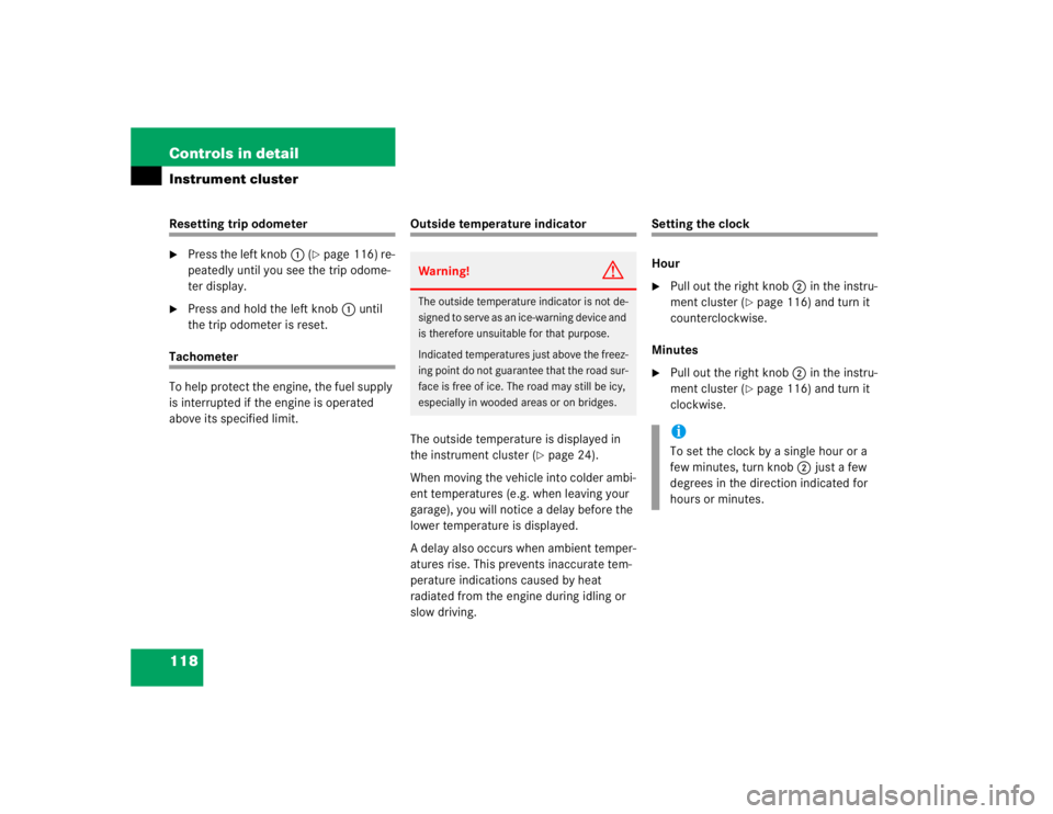
118 Controls in detailInstrument clusterResetting trip odometer�
Press the left knob1 (
�page 116) re-
peatedly until you see the trip odome-
ter display.
�
Press and hold the left knob1 until
the trip odometer is reset.
Tachometer
To help protect the engine, the fuel supply
is interrupted if the engine is operated
above its specified limit.
Outside temperature indicator
The outside temperature is displayed in
the instrument cluster (
�page 24).
When moving the vehicle into colder ambi-
ent temperatures (e.g. when leaving your
garage), you will notice a delay before the
lower temperature is displayed.
A delay also occurs when ambient temper-
atures rise. This prevents inaccurate tem-
perature indications caused by heat
radiated from the engine during idling or
slow driving.
Setting the clock
Hour�
Pull out the right knob2 in the instru-
ment cluster (
�page 116) and turn it
counterclockwise.
Minutes
�
Pull out the right knob2 in the instru-
ment cluster (
�page 116) and turn it
clockwise.
Warning!
G
The outside temperature indicator is not de-
signed to serve as an ice-warning device and
is therefore unsuitable for that purpose.
Indicated temperatures just above the freez-
ing point do not guarantee that the road sur-
face is free of ice. The road may still be icy,
especially in wooded areas or on bridges.
iTo set the clock by a single hour or a
few minutes, turn knob2 just a few
degrees in the direction indicated for
hours or minutes.
Page 961 of 4133
157 Controls in detail
Loading
�Loading
Loading instructions
The gross vehicle weight which is the
weight of the vehicle including fuel, tools,
spare wheel, installed accessories, pas-
sengers and luggage / cargo must never
exceed the Gross Vehicle Weight Rating
(GVWR) for your vehicle. In addition, the
load must be distributed in such a way so
that the weight on each axle never exceeds
the Gross Axle Weight Rating (GAWR) for
the front and rear axle. The GVWR and
GAWR for your vehicle are indicated on the
certification label which can be found on
the left door pillar.The handling characteristics of a fully load-
ed vehicle depend greatly on the load dis-
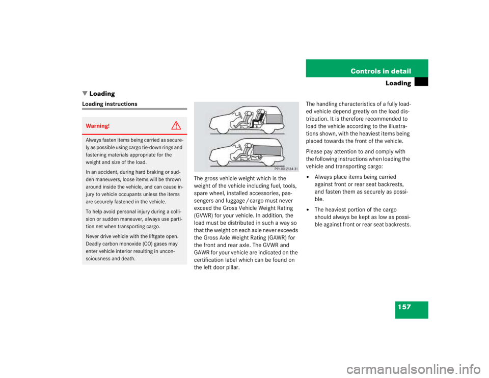
tribution. It is therefore recommended to
load the vehicle according to the illustra-
tions shown, with the heaviest items being
placed towards the front of the vehicle.
Please pay attention to and comply with
the following instructions when loading the
vehicle and transporting cargo:
�
Always place items being carried
against front or rear seat backrests,
and fasten them as securely as possi-
ble.
�
The heaviest portion of the cargo
should always be kept as low as possi-
ble against front or rear seat backrests.
Warning!
G
Always fasten items being carried as secure-
ly as possible using cargo tie-down rings and
fastening materials appropriate for the
weight and size of the load.
In an accident, during hard braking or sud-
den maneuvers, loose items will be thrown
around inside the vehicle, and can cause in-
jury to vehicle occupants unless the items
are securely fastened in the vehicle.
To help avoid personal injury during a colli-
sion or sudden maneuver, always use parti-
tion net when transporting cargo.
Never drive vehicle with the liftgate open.
Deadly carbon monoxide (CO) gases may
enter vehicle interior resulting in uncon-
sciousness and death.
Page 980 of 4133
176 Controls in detailUseful featuresWhen the connection is established, the
message
ROADSIDE ASSISTANCE –
CALL CONNECTED
appears in the MCS dis-
play. The Tele Aid system will transmit data
generating the vehicle identification num-
ber, model, color and location (subject to
availability of cellular and GPS signals).
A voice connection between the Roadside
Assistance dispatcher and the occupants
of the vehicle will be established. When a
voice connection is established the audio
system mutes and the message
TELE AID
– ROADSIDE ASSISTANCE CALL ACTIVE
ap-
pears in the MCS display.
�
Describe the nature of the need for as-
sistance.The Mercedes-Benz Roadside assistance
dispatcher will either dispatch a qualified
Mercedes-Benz technician or arrange to
tow your vehicle to the nearest
Mercedes-Benz Light Truck Center. For
services such as labor and / or towing,
charges may apply. Refer to the Roadside
Assistance manual for more information.
These programs are only available in the
USA:
�
Sign and Drive services: Services such
as jump start, a few gallons of fuel or
the replacement of a flat tire with the
vehicle spare tire are obtainable,
�
Remote Vehicle Diagnostics: This func-
tion permits the Mercedes-Benz Road-
side Assistance dispatcher to
download malfunction codes and actu-
al vehicle data.
iWhile the call is connected you can
change to navigation menu by pressing
NAVI button on the MCS unit.
iThe indicator lamp in the Roadside As-
sistance button• remains illumi-
nated in red for approx. ten seconds
during the system self-check after turn-
ing the key in the steering lock to
position2 (together with the SOS but-
ton and the Information button¡).
See system self-check (
�page 172)
when the indicator lamp does not light
up in red or stays on longer than ap-
proximately ten seconds.
Page 990 of 4133
186 Controls in detailUseful featuresTrip computer*
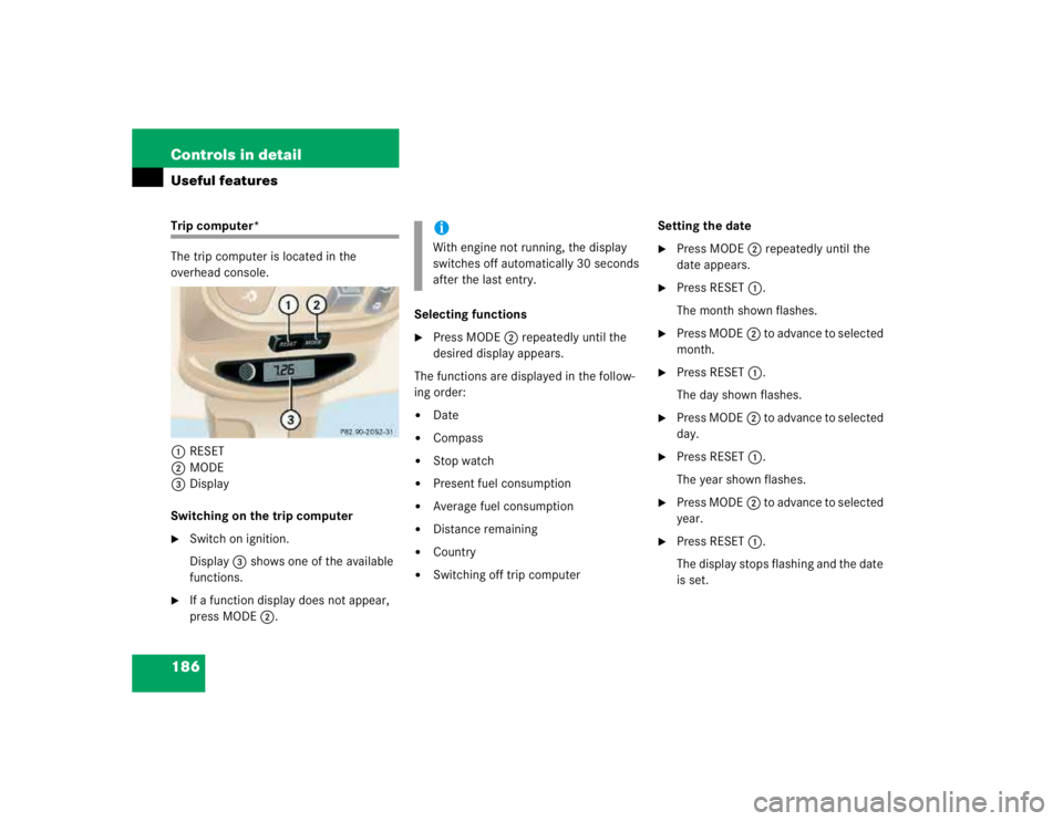
The trip computer is located in the
overhead console.
1RESET
2MODE
3Display
Switching on the trip computer�
Switch on ignition.
Display3 shows one of the available
functions.
�
If a function display does not appear,
press MODE2.Selecting functions
�
Press MODE2 repeatedly until the
desired display appears.
The functions are displayed in the follow-
ing order:
�
Date
�
Compass
�
Stop watch
�
Present fuel consumption
�
Average fuel consumption
�
Distance remaining
�
Country
�
Switching off trip computerSetting the date
�
Press MODE2 repeatedly until the
date appears.
�
Press RESET1.
The month shown flashes.
�
Press MODE2 to advance to selected
month.
�
Press RESET1.
The day shown flashes.
�
Press MODE2 to advance to selected
day.
�
Press RESET1.
The year shown flashes.
�
Press MODE2 to advance to selected
year.
�
Press RESET1.
The display stops flashing and the date
is set.
iWith engine not running, the display
switches off automatically 30 seconds
after the last entry.