1997 MERCEDES-BENZ ML430 air filter
[x] Cancel search: air filterPage 3236 of 4133
Fig. 9: Replacing Intake Air Dust Filter
Courtesy of MERCEDES-BENZ OF NORTH AMERICA.
RECEIVER-DRIER
Removal & Installation
1. Discharge A/C system, using approved refrigerant recovery/recycling equipment. Remove headlight
units. Remove headlight units. Remove upper frame crossmember, release hood release control cable and
remove crossmember. See Fig. 6
.
2. Remove bolts from receiver-drier refrigerant lines. See Fig. 5
. Disconnect refrigerant lines from receiver-
drier. Plug exposed openings to protect A/C system from debris and moisture. Discard "O" rings. Loosen
receiver-drier clamp bolt. Remove receiver-drier. To install, reverse removal procedure.
3. When installing a new receiver-drier, add 0.34 ounce of NEW refrigerant oil to receiver-drier. Use NEW
"O" rings. Tighten refrigerant line bolts to specification. See TORQUE SPECIFICATIONS
.
TORQUE SPECIFICATIONS
TORQUE SPECIFICATIONS
WIRING DIAGRAMS
ApplicationFt. Lbs. (N.m)
Compressor Mounting Bolts15 (20)
Refrigerant Line-To-Compressor Bolt15 (20)
Refrigerant Line-To-Condenser Bolt15 (20)
Steering Column Bolt15 (20)
Steering Column Nut13 (18)
INCH Lbs. (N.m)
Expansion Valve Self-Locking Nut89 (10)
Refrigerant Line-To-Receiver-Drier Bolt89 (10)
2001 Mercedes-Benz ML320
2000-01 MANUAL A/C-HEATER SYSTEMS ML 320, ML 430 & ML 55
me
Saturday, October 02, 2010 3:25:10 PMPage 25 © 2006 Mitchell Repair Information Company, LLC.
Page 3250 of 4133
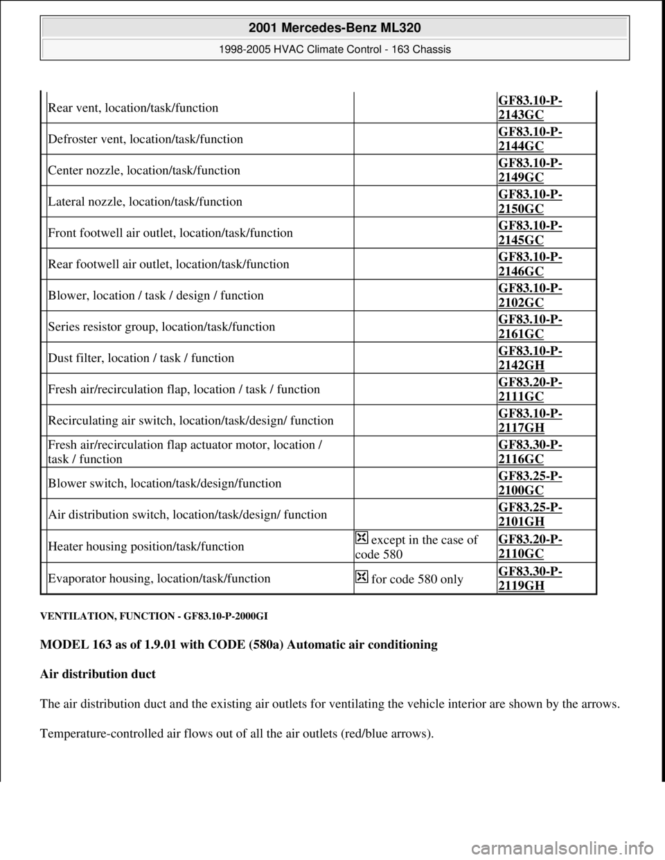
VENTILATION, FUNCTION - GF83.10-P-2000GI
MODEL 163 as of 1.9.01 with CODE (580a) Automatic air conditioning
Air distribution duct
The air distribution duct and the existing air outlets for ventilating the vehicle interior are shown by the arrows.
Temperature-controlled air flows out of all the air outlets (red/blue arrows).
Rear vent, location/task/function GF83.10-P-
2143GC
Defroster vent, location/task/function GF83.10-P-
2144GC
Center nozzle, location/task/function GF83.10-P-
2149GC
Lateral nozzle, location/task/function GF83.10-P-
2150GC
Front footwell air outlet, location/task/function GF83.10-P-
2145GC
Rear footwell air outlet, location/task/function GF83.10-P-
2146GC
Blower, location / task / design / function GF83.10-P-
2102GC
Series resistor group, location/task/function GF83.10-P-
2161GC
Dust filter, location / task / function GF83.10-P-
2142GH
Fresh air/recirculation flap, location / task / function GF83.20-P-
2111GC
Recirculating air switch, location/task/design/ function GF83.10-P-
2117GH
Fresh air/recirculation flap actuator motor, location /
task / function GF83.30-P-
2116GC
Blower switch, location/task/design/function GF83.25-P-
2100GC
Air distribution switch, location/task/design/ function GF83.25-P-
2101GH
Heater housing position/task/function except in the case of
code 580GF83.20-P-
2110GC
Evaporator housing, location/task/function for code 580 onlyGF83.30-P-
2119GH
2001 Mercedes-Benz ML320
1998-2005 HVAC Climate Control - 163 Chassis
me
Saturday, October 02, 2010 3:23:14 PMPage 6 © 2006 Mitchell Repair Information Company, LLC.
Page 3253 of 4133
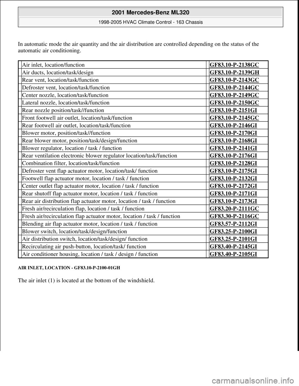
In automatic mode the air quantity and the air distribution are controlled depending on the status of the
automatic air conditioning.
AIR INLET, LOCATION - GF83.10-P-2100-01GH
The air inlet (1) is located at the bottom of the windshield.
Air inlet, location/function GF83.10-P-2138GC
Air ducts, location/task/design GF83.10-P-2139GH
Rear vent, location/task/function GF83.10-P-2143GC
Defroster vent, location/task/function GF83.10-P-2144GC
Center nozzle, location/task/function GF83.10-P-2149GC
Lateral nozzle, location/task/function GF83.10-P-2150GC
Rear nozzle position/task//function GF83.10-P-2151GI
Front footwell air outlet, location/task/function GF83.10-P-2145GC
Rear footwell air outlet, location/task/function GF83.10-P-2146GI
Blower motor, position/task//function GF83.10-P-2170GI
Rear blower motor, position/task/design/function GF83.10-P-2168GI
Blower regulator, location / task / function GF83.10-P-2141GI
Rear ventilation electronic blower regulator location/task/function GF83.10-P-2176GI
Combination filter, location/task/function GF83.10-P-2128GI
Defroster vent flap actuator motor, location/task/ function GF83.10-P-2175GI
Footwell flap actuator motor, location / task / function GF83.10-P-2132GI
Center outlet flap actuator motor, location / task / function GF83.10-P-2172GI
Rear shutoff flap actuator motor, location / task / function GF83.10-P-2171GI
Rear air distribution flap actuator motor, location / task / function GF83.10-P-2173GI
Fresh air/recirculation flap, location / task / function GF83.20-P-2111GC
Fresh air/recirculation flap actuator motor, location / task / function GF83.30-P-2116GC
Blending air flap actuator motor, location / task / function GF83.57-P-2112GI
Blower switch, location/task/design/function GF83.25-P-2100GI
Air distribution switch, location/task/design/ function GF83.25-P-2101GI
Recirculating air push-button, location/task/ function GF83.40-P-2145GI
Air conditioner housing, location / task / design / function GF83.40-P-2105GI
2001 Mercedes-Benz ML320
1998-2005 HVAC Climate Control - 163 Chassis
me
Saturday, October 02, 2010 3:23:14 PMPage 9 © 2006 Mitchell Repair Information Company, LLC.
Page 3258 of 4133
The blower regulator then controls the blower motor operating voltage, depending on the actual measured in-car
temperature and the selected target temperature
(0-12 V). This facilitates blower speed control of 0-100 %.
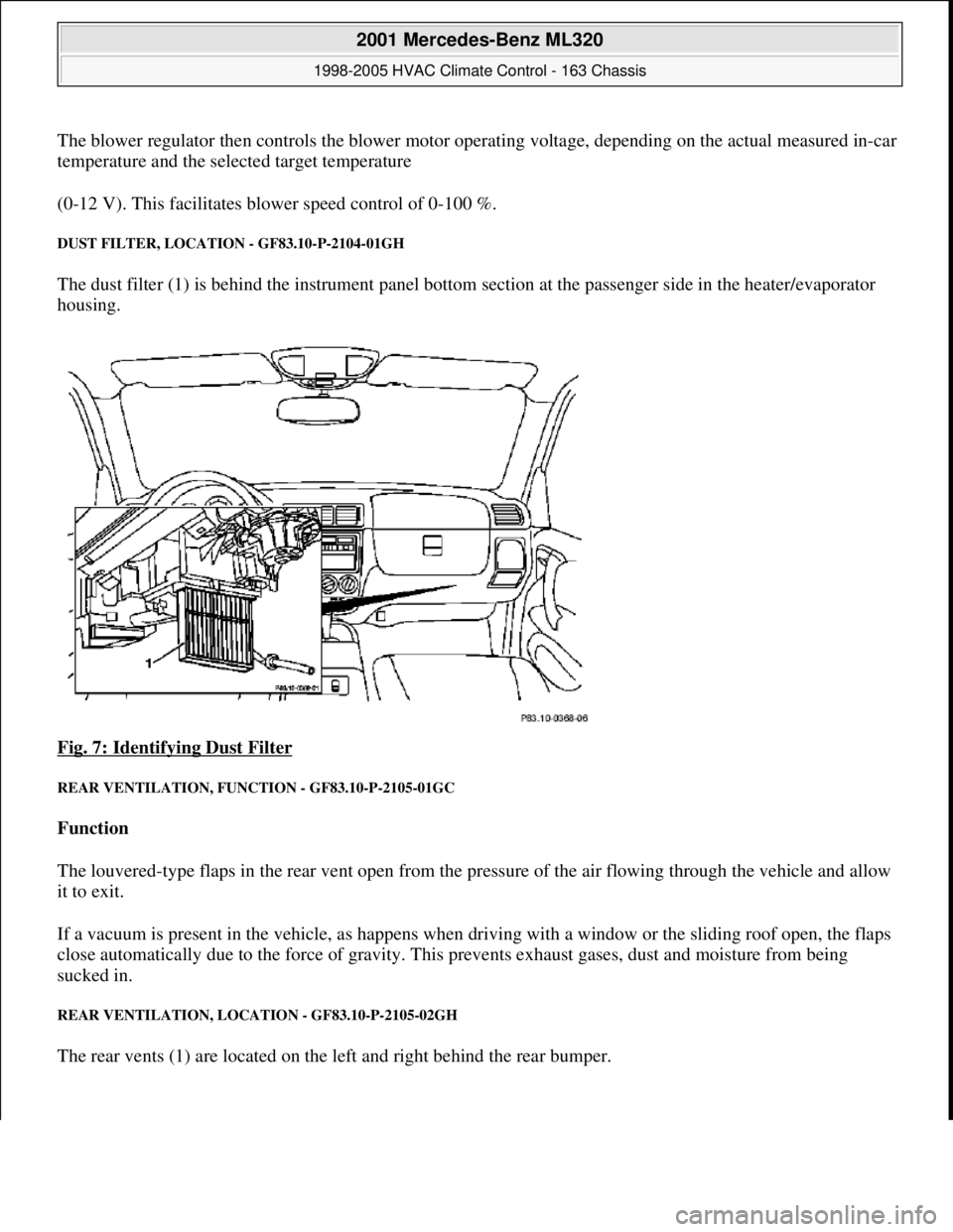
DUST FILTER, LOCATION - GF83.10-P-2104-01GH
The dust filter (1) is behind the instrument panel bottom section at the passenger side in the heater/evaporator
housing.
Fig. 7: Identifying Dust Filter
REAR VENTILATION, FUNCTION - GF83.10-P-2105-01GC
Function
The louvered-type flaps in the rear vent open from the pressure of the air flowing through the vehicle and allow
it to exit.
If a vacuum is present in the vehicle, as happens when driving with a window or the sliding roof open, the flaps
close automatically due to the force of gravity. This prevents exhaust gases, dust and moisture from being
sucked in.
REAR VENTILATION, LOCATION - GF83.10-P-2105-02GH
The rear vents (1) are located on the left and right behind the rear bumper.
2001 Mercedes-Benz ML320
1998-2005 HVAC Climate Control - 163 Chassis
me
Saturday, October 02, 2010 3:23:14 PMPage 14 © 2006 Mitchell Repair Information Company, LLC.
Page 3267 of 4133
The series resistor assembly (R14) is comprised of three resistors which can be interconnected, via series
connection, to form an overall resistor. Depending on the setting of the blower switch, current is guided via the
resistors assigned to the set blower level to the blower (M2). Different control voltages are therefore present at
the blower (M2), as a result of which the blower (M2) operates at different rotational speeds.
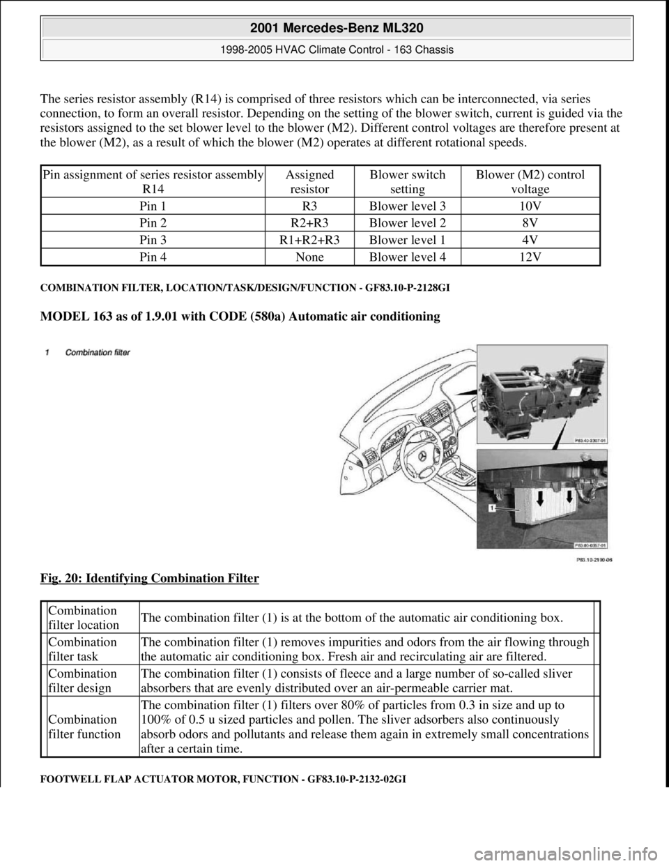
COMBINATION FILTER, LOCATION/TASK/DESIGN/FUNCTION - GF83.10-P-2128GI
MODEL 163 as of 1.9.01 with CODE (580a) Automatic air conditioning
Fig. 20: Identifying Combination Filter
FOOTWELL FLAP ACTUATOR MOTOR, FUNCTION - GF83.10-P-2132-02GI
Pin assignment of series resistor assembly
R14Assigned
resistorBlower switch
settingBlower (M2) control
voltage
Pin 1R3Blower level 310V
Pin 2R2+R3Blower level 28V
Pin 3R1+R2+R3Blower level 14V
Pin 4NoneBlower level 412V
Combination
filter locationThe combination filter (1) is at the bottom of the automatic air conditioning box.
Combination
filter taskThe combination filter (1) removes impurities and odors from the air flowing through
the automatic air conditioning box. Fresh air and recirculating air are filtered.
Combination
filter designThe combination filter (1) consists of fleece and a large number of so-called sliver
absorbers that are evenly distributed over an air-permeable carrier mat.
Combination
filter function
The combination filter (1) filters over 80% of particles from 0.3 in size and up to
100% of 0.5 u sized particles and pollen. The sliver adsorbers also continuously
absorb odors and pollutants and release them again in extremely small concentrations
after a certain time.
2001 Mercedes-Benz ML320
1998-2005 HVAC Climate Control - 163 Chassis
me
Saturday, October 02, 2010 3:23:15 PMPage 23 © 2006 Mitchell Repair Information Company, LLC.
Page 3271 of 4133
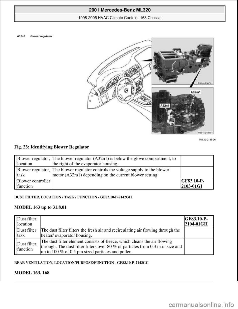
Fig. 23: Identifying Blower Regulator
DUST FILTER, LOCATION / TASK / FUNCTION - GF83.10-P-2142GH
MODEL 163 up to 31.8.01
REAR VENTILATION, LOCATION/PURPOSE/FUNCTION - GF83.10-P-2143GC
MODEL 163, 168
Blower regulator,
locationThe blower regulator (A32n1) is below the glove compartment, to
the right of the evaporator housing.
Blower regulator,
taskThe blower regulator controls the voltage supply to the blower
motor (A32m1) depending on the current blower setting.
Blower controller
function GF83.10-P-
2103-01GI
Dust filter,
location GF83.10-P-
2104-01GH
Dust filter
taskThe dust filter filters the fresh air and recirculating air flowing through the
heater/ evaporator housing.
Dust filter,
functionThe dust filter element consists of fleece, which cleans the air flowing
through. The dust filter filters over 80 % of particles from 0.3 m in size and
up to 100 % of 0.5 pm sized particles and pollen.
2001 Mercedes-Benz ML320
1998-2005 HVAC Climate Control - 163 Chassis
me
Saturday, October 02, 2010 3:23:15 PMPage 27 © 2006 Mitchell Repair Information Company, LLC.
Page 3286 of 4133
Control is then carried out there as follows:
Temperature selector wheel MAX setting (full heater output)
Due to the setting of the blending air flaps, the drawn in air is routed through the heat exchanger. Heated
cooling water generally flows through this, as a result of which the passing air is heated. The temperature-
controlled air is guided into the vehicle interior via the various air outlets.
Temperature selector wheel MIN setting (no heater output)
In this setting, the blending air flaps block the route to the heat exchanger. The drawn in fresh air is guided
directly to the air outlets and therefore into the vehicle interior.
HEATER FUNCTIONAL DESCRIPTION TABLE OF CONTENTS - GF83.20-P-0998GH
MODEL 163 up to 31.8.01 except CODE (580) Air conditioning or Tempmatic for USA
Ventilation system function GF83.10-P-2000GH
Heater circuit function GF83.20-P-2003GH
Heater controls, function GF83.20-P-2004GH
Heater function GF83.20-P-0002GH
Ventilation system function GF83.10-P-2000GH
Heater circuit function GF83.20-P-2003GH
Heater controls, function GF83.20-P-2004GH
Air inlet, location/function GF83.10-P-2138GC
Air ducts, location/task/design GF83.10-P-2139GH
Blower, location/task/design/function GF83.10-P-2102GC
Series resistor group, location/task/function GF83.10-P-2161GC
Dust filter, location/task/function GF83.10-P-2142GH
Rear vent, location/task/function GF83.10-P-2143GC
Defroster vent, location/task/function GF83.10-P-2144GC
Center nozzle, location/task/function GF83.10-P-2149GC
Lateral nozzle, location/task/function GF83.10-P-2150GC
Front footwell air outlet, location/task/function GF83.10-P-2145GC
Rear footwell air outlet, location/task/function GF83.10-P-2146GC
Heating system heat exchanger, location/ purpose/function GF83.20-P-2108GC
Fresh air/recirculated air flap, location/task/ function GF83.20-P-2111GC
Fresh air/recirculated air flap actuator, location/ task/function GF83.30-P-2116GC
Blower switch, location/task/design/function GF83.25-P-2100GC
Air distribution switch, location/task/design/ function GF83.25-P-2101GH
Temperature selector wheel, location/task/ design/function GF83.25-P-2102GC
Air recirculation switch, location/task/design/ function GF83.10-P-2117GH
2001 Mercedes-Benz ML320
1998-2005 HVAC Climate Control - 163 Chassis
me
Saturday, October 02, 2010 3:23:15 PMPage 42 © 2006 Mitchell Repair Information Company, LLC.
Page 3291 of 4133
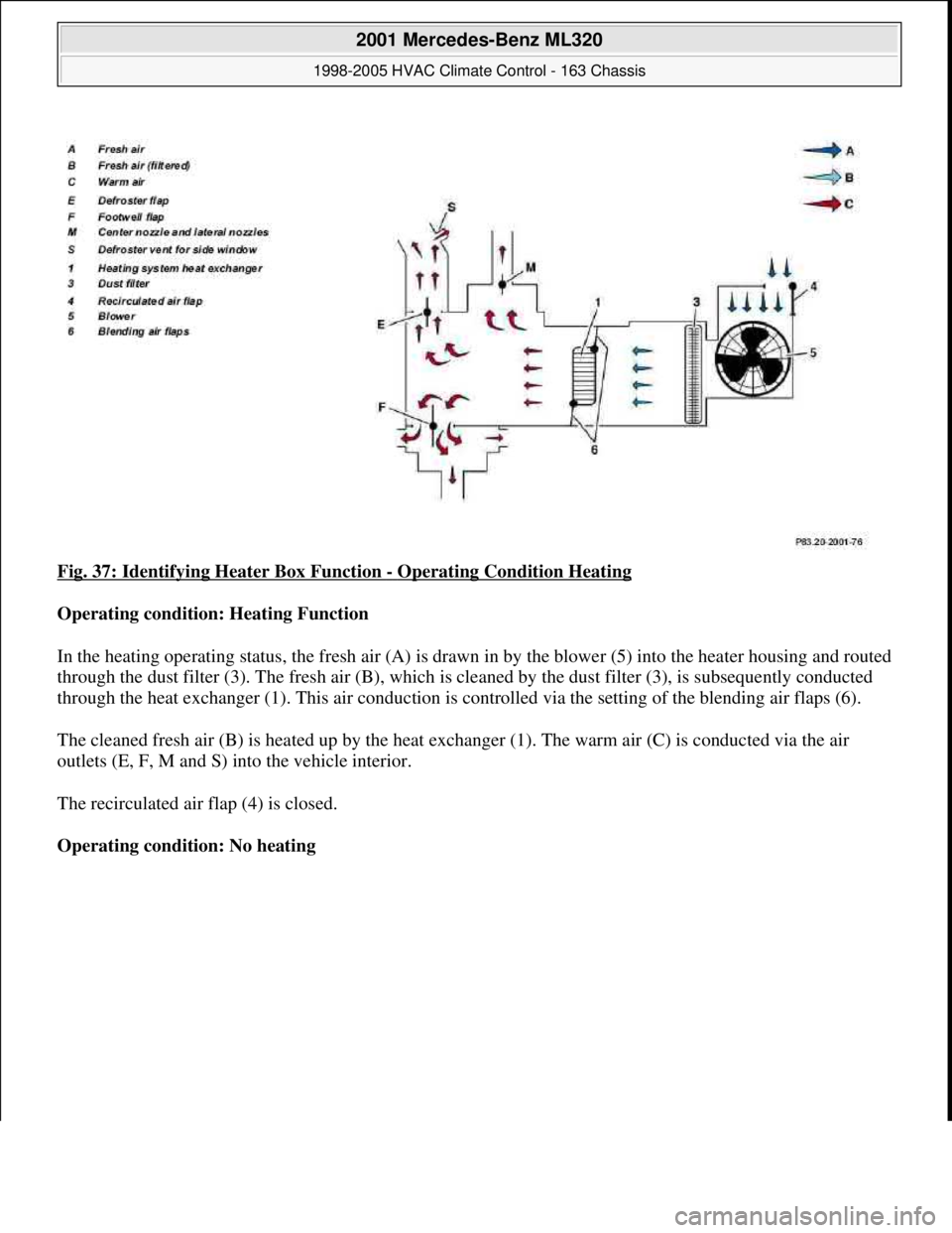
Fig. 37: Identifying Heater Box Function - Operating Condition Heating
Operating condition: Heating Function
In the heating operating status, the fresh air (A) is drawn in by the blower (5) into the heater housing and routed
through the dust filter (3). The fresh air (B), which is cleaned by the dust filter (3), is subsequently conducted
through the heat exchanger (1). This air conduction is controlled via the setting of the blending air flaps (6).
The cleaned fresh air (B) is heated up by the heat exchanger (1). The warm air (C) is conducted via the air
outlets (E, F, M and S) into the vehicle interior.
The recirculated air flap (4) is closed.
Operating condition: No heating
2001 Mercedes-Benz ML320
1998-2005 HVAC Climate Control - 163 Chassis
me
Saturday, October 02, 2010 3:23:15 PMPage 47 © 2006 Mitchell Repair Information Company, LLC.