1997 MERCEDES-BENZ ML430 air filter
[x] Cancel search: air filterPage 3474 of 4133
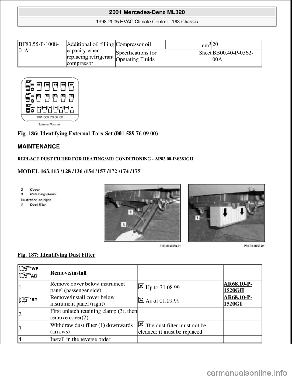
Fig. 186: Identifying External Torx Set (001 589 76 09 00)
MAINTENANCE
REPLACE DUST FILTER FOR HEATIN G/AIR CONDITIONING - AP83.00-P-8381GH
MODEL 163.113 /128 /136 /154 /157 /172 /174 /175
Fig. 187: Identifying Dust Filter
BF83.55-P-1008-
01AAdditional oil filling
capacity when
replacing refrigerant
compressorCompressor oilcm3 20
Specifications for
Operating FluidsSheetBB00.40-P-0362-
00A
Remove/install
1Remove cover below instrument
panel (passenger side) Up to 31.08.99AR68.10-P-
1520GH
Remove/install cover below
instrument panel (right) As of 01.09.99AR68.10-P-
1520GI
2First unlatch retaining clamp (3), then
remove cover(2)
3Withdraw dust filter (1) downwards
(arrows) The dust filter must not be
cleaned; it must be replaced.
4Install in the reverse order
2001 Mercedes-Benz ML320
1998-2005 HVAC Climate Control - 163 Chassis
me
Saturday, October 02, 2010 3:23:19 PMPage 230 © 2006 Mitchell Repair Information Company, LLC.
Page 3688 of 4133
T P56 DREISEITENKIPPER (MEILLER)
P P57 FUNKAUSRUESTUNG BOSCH FUG-8B1
P P58 FUNKAUSRUESTUNG AEG / BOSCH
P P59 FUNKAUSRUESTUNG BOSCH / BOSCH
P P60 POLIZEIFAHRZEUG IRAN
P P62 VORRUESTUNG FUNKGERAET MOTOROLA GM 950
P P63 VORRUESTUNG FUNKGERAET MOTOROLA MAX TRAC
P P64 ANTENNE AUF DACH HI UHF-FREQUENZ
P P65 LAPTOP-VORRUESTUNG MOTOROLA GM 950
P P66 LAPTOP-VORRUESTUNG MOTOROLA MAX TRAC
P P67 FOLIE RUNDHERUM GRUEN, POLIZEI IRAN
P P68 FOLIE RUNDHERUM BLAU, POLIZEI IRAN
P P69 FOLIE BEWEGLICHE TEILE GRUEN, POLIZEI IRAN
P P70 FOLIE BEWEGLICHE TEILE BLAU, POLIZEI IRAN
P P75 SONDERMODELL AUTOVERMIETER
P P76 SONDERMODELL FASCINATION
T PB0 WEGFALL ABS,ABD (ETS) UND FAHRER-AIRBAG
T PG3 INTEGRALKOFFER MIT REGALEINBAU
T PG4 INTEGRALKOFFER OHNE REGALEINBAU
T PG5 INTEGRALKOFFER FUER UPS
T PQ3 *** UNG *** WIRD CODE PG3
P Q01 LU DECKEL KW-ABDICHTUNG HINTEN (LFT.BRUSS)
P Q02 GV - RADIALWELLENDICHTRING, LFT. KACO
P Q03 GV - KW-LAGERDECKELSCHRAUBEN 10 MN SI 7
P Q04 GV-8MMHUELSENKETTE
P Q05 GV - ZB KOLBEN, LFT. MAHLE
P Q06 RAIL ENTFALL STABFILTER
P Q07 GV - LU DECKEL (KW-ABDICHTUNG HI)
P Q08 GV - KOLBEN KUNSTSTOFFBESCHICHTET LFT MAHLE
P Q09 GV - KW-LAGERDECKELSCHRAUBEN 10 MN SI 7
T Q10 QUERTRAEGER FEUR AK
P Q10 GV - ZYLINDERKOPFDICHTUNG MIT ZUS. SICKENABDICHTG.
P Q11 GV - LU RIEMENSPANNER FA.LITENS
P Q12 GV - LU RIEMENSPANNER LFT.FA.INA
P Q13 GV-ZB TUERSCHLOSS FRONDTUER M INTEGRIERTER ABDECK.
P Q14 ABGASREINIGUNGSANLAGE EU4 (OXIKAT)
P Q15 GEREGELTE WASSERPUMPE
P Q16 GROSSVERSUCH AS GETRIEBE
P Q17 GV - DICHTUNG (ZW. ATL UND APK)
P Q18 GV - ZB OELPUMPE
P Q19 VERZAHNUNGSVARIANTE FUER PORSCHE
T Q20 ANHAENGERKUPPLUNG (MAULKUPPLUNG 243 / U 115)
P Q20 GV - METALLAGEN - ZYLINDERKOPFDICHTUNG
T Q21 ANHAENGERKUPPLUNG 256 G 113
P Q21 UNG./GV-SILIKON ZYL.-KOPFDICHTUNG (UNVERLIERBAR)
P Q22 GV FAHRERKISSEN BR 202/210
T Q22 ANHAENGERKUPPLUNG FEST
T Q23 ANHAENGERKUPPLUNG MAULKUPPLUNG 243 U115 EL
P Q24 GV - PLEUELLAGER LFT KS
T Q24 ANHAENGERKUPPLUNG FEST, US KUGELKOPF
P Q25 GV - SPANNSCHIENE VOLLKUNSTSTOFFAUSF. LFT BOSCH
P Q26 GV - SCHWUNGRADSCHRAUBE LFT FONTANA
P Q28 GV - LU RIEMENSPANNER MECHANISCH FA.LITENS
P Q29 GV - VENTILE DES LFT EATON
P Q30 GV - SEILZUEGE AN RSL-BOX O.SCHAUMSTOFFUMMANTELUNG
P Q33 ELEKTR.ZUHEIZER F.WAGENHEIZUNG IN KGH INTEGRIERT
P Q34 GV - ZB GENERATOR MIT FREILAUFRIEMENSCHEIBE
P Q35 GV - GEBAUTE NOCKENWELLEN
P Q36 GV - ZB WASSERPUMPE
P Q37 GV - KEILRIPPENRIEMEN LFT HUTCHINSON
P Q38 GV-ZYLINDERKOPFDICHTUNG MIT VITONELEMENT
P Q39 GV - BUNDSCHRAUBE
P Q40 GV - RADIALWELLENDICHTRING (LFT.BRUSS)
P Q43 DICHTUNG WASSERPUMPE
P Q44 DICHTUNG WASSERPUMPE
Page 3719 of 4133
AP18.00-P-0101-06EG
Replace oil filter element, drain oil filter
Crankcase ventilation, cylinder head cover
Number
Designation
Engine
611.960/
961/962
Engine
612.961/
962/967
Engine
612.963
Engine
612.965/
966
Engine
613.960/
961
BA01.20-P-1002-01A
Screw of trim panel of cylinder head cover
to cylinder head cover
Nm
1010101010
BA01.20-P-1003-01A
Screw attaching cover panel to charge air
distribution pipe
Nm
1010101010
Crankcase ventilation, cylinder head cover
Number
Designation
Engine
646.951/961,
647
Engine
646.962/963
Engine
648
BA01.20-P-1002-01G
Bolt, trim panel of cylinder
head cover to cylinder head
Nm
999
BA01.20-P-1003-01G
Bolt, cover to charge air
distribution pipe.
Nm
999
Designation
Engine
611.960/
961/962
Engine
612.961/962/
963/990,
613.960/961
Engine
612.965/
966
Engine
646.951/961/
962/963/982/
983/984,
647, 648
BA18.20-P-1002-01G
Screw cap at oil filter
Nm
25252525
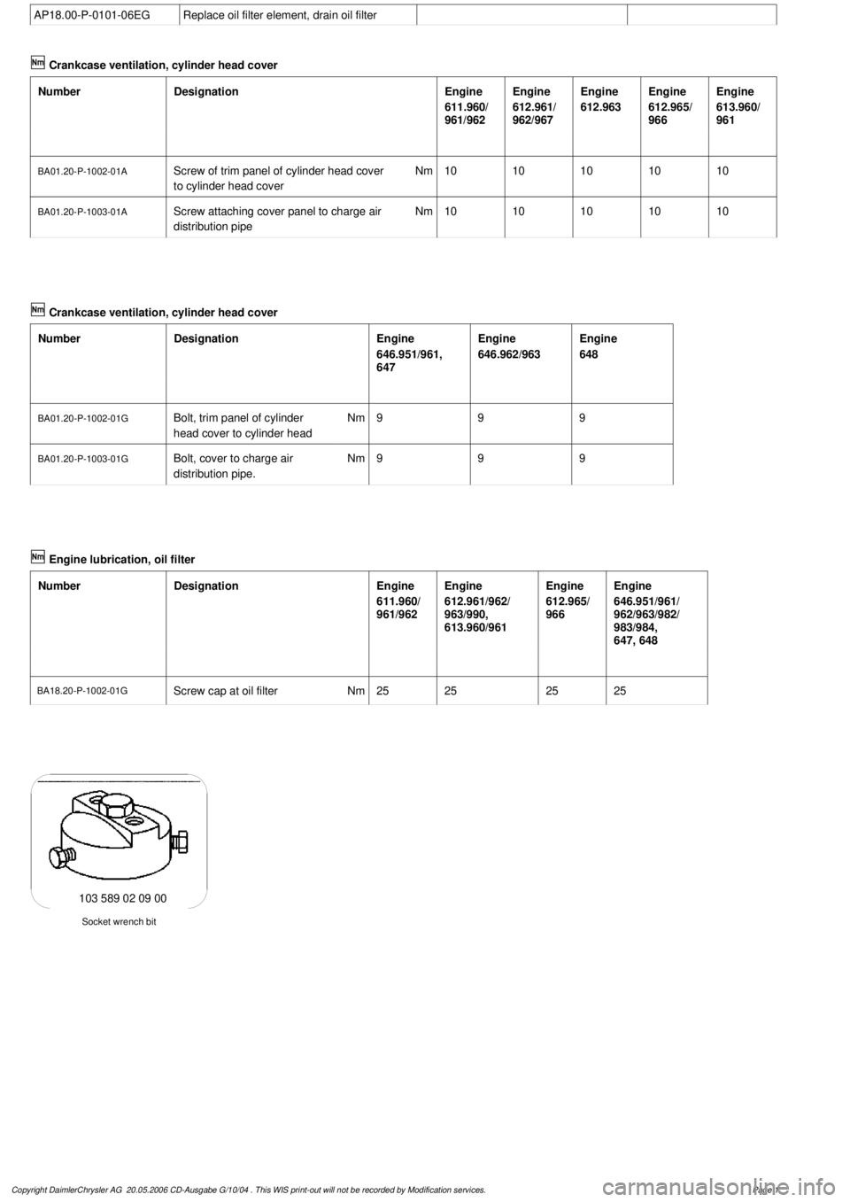
Socket wrench bit
103 589 02 09 00
Copyright DaimlerChrysler AG 20.05.2006 CD-Ausgabe G/10/04 . This WIS print-out will not be recorde
d by Modification services.
Page 1
Page 3720 of 4133
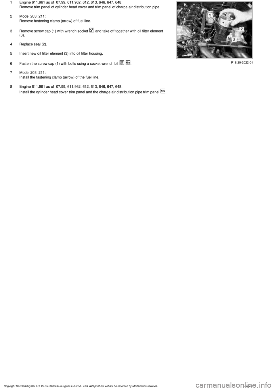
P18.20-2022-01
1
Engine 611.961 as of 07.99, 611.962, 612, 613, 646, 647, 648:
Remove trim panel of cylinder head cover and trim panel of charge air distribution pipe.
2
Model 203, 211:
Remove fastening clamp (arrow) of fuel line.
3
Remove screw cap (1) with wrench socket
and take off together with oil filter element
(3).
4
Replace seal (2).
5
Insert new oil filter element (3) into oil filter housing.
6
Fasten the screw cap (1) with bolts using a socket wrench bit
.
7
Model 203, 211:
Install the fastening clamp (arrow) of the fuel line.
8
Engine 611.961 as of 07.99, 611.962, 612, 613, 646, 647, 648:
Install the cylinder head cover trim panel and the charge air distribution pipe trim panel
.
Copyright DaimlerChrysler AG 20.05.2006 CD-Ausgabe G/10/04 . This WIS print-out will not be recorde
d by Modification services.
Page 2
Page 3775 of 4133
AP15.10-P-1580GHReplace spark plugs
1.7.97
ENGINE
112.942 in MODEL 163.154
ENGINE
112.970 in MODEL 163.157
ENGINE
113.942 in MODEL 163.172
ENGINE
113.981 in MODEL 163.174
ENGINE
113.965 in MODEL 163.175
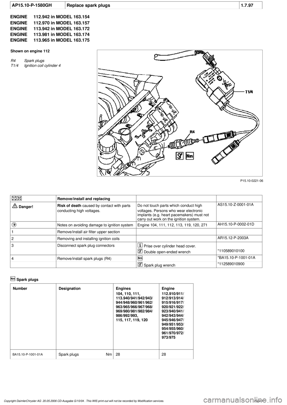
P15.10-0221-06
Shown on engine 112
R4
Spark plugs
T1/4
Ignition coil cylinder 4
Remove/install and replacing
Danger!
Risk of death
caused by contact with parts
conducting high voltages.
Do not touch parts which conduct high
voltages. Persons who wear electronic
implants (e.g. heart pacemakers) must not
carry out work on the ignition system.
AS15.10-Z-0001-01A
Notes on avoiding damage to ignition system
Engine 104, 111, 112, 113, 119, 120, 271
AH15.10-P-0002-01D
1
Remove/install air filter upper section
2
Removing and installing ignition coils
AR15.12-P-2003A
3
Disconnect spark plug connectors
Prise over cylinder head cover.
Double open-ended wrench
*110589010100
4
Remove/install spark plugs (R4)
*BA15.10-P-1001-01A
Spark plug wrench
*112589010900
Spark plugs
Number
Designation
Engines
104, 110, 111,
113.940/941/942/943/
944/948/960/961/962/
963/965/966/967/968/
969/980/981/982/984/
986/992/993,
115, 117, 119, 120
Engine
112.910/911/
912/913/914/
915/916/917/
920/921/922/
923/940/941/
942/943/944/
945/946/947/
949/951/953/
954/955/960/
961/970/972/
973/975
BA15.10-P-1001-01A
Spark plugs
Nm
2828
Copyright DaimlerChrysler AG 20.05.2006 CD-Ausgabe G/10/04 . This WIS print-out will not be recorde
d by Modification services.
Page 1
Page 3836 of 4133

Measures for slightly sludged engine:
Oil and filter change. Purge engine, i.e. normal engine operation
in neutral, or while driving, using oil from Sheet 229.3, 228.3, or
228.5. Drain off scavenging oil after purging process (approx. 1
hour). Repeat purging process if necessary. Refill using engine oil
from Sheet 229.3, or 229.1. The first oil change after clearing the
sludge should be performed after approx. 10,000 km or beforehand;
when doing so use engine oil from Sheet 229.3.
Measures for severely sludged engine:
Engines with severe oil sludging and caking onto engine parts
and into bores have to be dismantled and mechanically cleaned.
Tough sludge residue must not enter the clean side of the oil circuit,
as otherwise, e.g. the piston oil spray and the hydraulic
compensation elements may have their functionality impaired. Refill
using engine oil from Sheet 229.3, or 229.1.
The first oil change after sludging should be performed after approx.
10,000 km; when doing so use engine oil from
Sheet 229.3.
Warranty/goodwill regulations
If in combination with engine oil sludging a warranty/goodwill claim is
submitted, then a regular documentation of maintenance must be
presented. The ASSYST printout is to be filed carefully for further
reference.
Oil sludging in combination with an exceeded oil change interval, or
because of special additives in the fuel/engine oil are costs to be
borne by the customer.
Copyright DaimlerChrysler AG 20.05.2006 CD-Ausgabe G/10/04 . This WIS print-out will not be recorde
d by Modification services.
Page 2
Page 3989 of 4133
AR40.15-P-0080A
Remove/install wheel sensor
1.4.99
MODELS
210.074 /274 with CODE (475) Tire pressure indicator
MODELS
211 with CODE (475) Tire pressure indicator
MODELS
215 with CODE (475) Tire pressure indicator
MODELS
220 with CODE (475) Tire pressure indicator
MODELS
230 with CODE (475) Tire pressure indicator
MODELS
240 with CODE (475) Tire pressure indicator
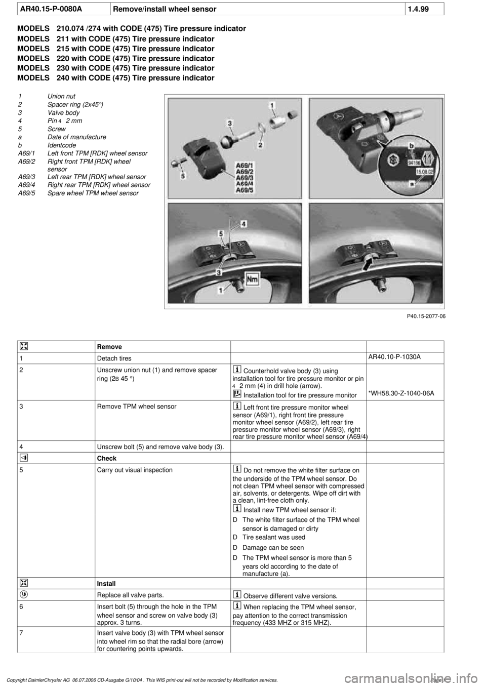
P40.15-2077-06
1
Union nut
2
Spacer ring (2x45°)
3
Valve body
4
Pin
4
2 mm
5
Screw
a
Date of manufacture
b
Identcode
A69/1
Left front TPM [RDK] wheel sensor
A69/2
Right front TPM [RDK] wheel
sensor
A69/3
Left rear TPM [RDK] wheel sensor
A69/4
Right rear TPM [RDK] wheel sensor
A69/5
Spare wheel TPM wheel sensor
Remove
1
Detach tires
AR40.10-P-1030A
2
Unscrew union nut (1) and remove spacer
ring (2
B
45 °)
Counterhold valve body (3) using
installation tool for tire pressure monitor or pin
4
2 mm (4) in drill hole (arrow).
Installation tool for tire pressure monitor
*WH58.30-Z-1040-06A
3
Remove TPM wheel sensor
Left front tire pressure monitor wheel
sensor (A69/1), right front tire pressure
monitor wheel sensor (A69/2), left rear tire
pressure monitor wheel sensor (A69/3), right
rear tire pressure monitor wheel sensor (A69/4)
4
Unscrew bolt (5) and remove valve body (3).
Check
5
Carry out visual inspection
Do not remove the white filter surface on
the underside of the TPM wheel sensor. Do
not clean TPM wheel sensor with compressed
air, solvents, or detergents. Wipe off dirt with
a clean, lint-free cloth only.
Install new TPM wheel sensor if:
D
The white filter surface of the TPM wheel
sensor is damaged or dirty
D
Tire sealant was used
D
Damage can be seen
D
The TPM wheel sensor is more than 5
years old according to the date of
manufacture (a).
Install
Replace all valve parts.
Observe different valve versions.
6
Insert bolt (5) through the hole in the TPM
wheel sensor and screw on valve body (3)
approx. 3 turns.
When replacing the TPM wheel sensor,
pay attention to the correct transmission
frequency (433 MHZ or 315 MHZ).
7
Insert valve body (3) with TPM wheel sensor
into wheel rim so that the radial bore (arrow)
for countering points upwards.
Copyright DaimlerChrysler AG 06.07.2006 CD-Ausgabe G/10/04 . This WIS print-out will not be recorde
d by Modification services.
Page 1