Page 3292 of 4133
Fig. 38: Identifying Heater Box Function - Operating Condition No Heating
Operating condition: No heating Function
In the "no heating" operating status, the fresh air (A) is drawn in by the blower (5) into the heater housing and
routed through the dust filter (3).
The fresh air (B), which is cleaned by the dust filter (3), is subsequently routed around the heat exchanger (1).
This air conduction is controlled via the setting of the blending air flaps (6).
The cleaned fresh air (B) is routed directly into the passenger compartment via the air outlets (E, F, M and S).
The recirculated air flap (4) is closed.
Operating condition: No "recirculated air" heating
2001 Mercedes-Benz ML320
1998-2005 HVAC Climate Control - 163 Chassis
me
Saturday, October 02, 2010 3:23:15 PMPage 48 © 2006 Mitchell Repair Information Company, LLC.
Page 3293 of 4133
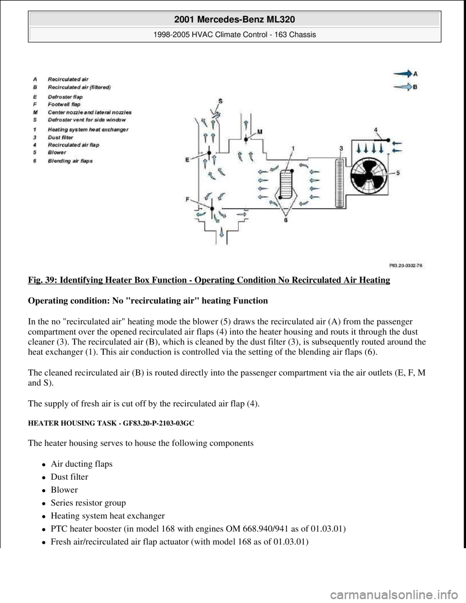
Fig. 39: Identifying Heater Box Function - Operating Condition No Recirculated Air Heating
Operating condition: No "recirculating air" heating Function
In the no "recirculated air" heating mode the blower (5) draws the recirculated air (A) from the passenger
compartment over the opened recirculated air flaps (4) into the heater housing and routs it through the dust
cleaner (3). The recirculated air (B), which is cleaned by the dust filter (3), is subsequently routed around the
heat exchanger (1). This air conduction is controlled via the setting of the blending air flaps (6).
The cleaned recirculated air (B) is routed directly into the passenger compartment via the air outlets (E, F, M
and S).
The supply of fresh air is cut off by the recirculated air flap (4).
HEATER HOUSING TASK - GF83.20-P-2103-03GC
The heater housing serves to house the following components
Air ducting flaps
Dust filter
Blower
Series resistor group
Heating system heat exchanger
PTC heater booster (in model 168 with engines OM 668.940/941 as of 01.03.01)
Fresh air/recirculated air flap actuator (with model 168 as of 01.03.01)
2001 Mercedes-Benz ML320
1998-2005 HVAC Climate Control - 163 Chassis
me
Saturday, October 02, 2010 3:23:15 PMPage 49 © 2006 Mitchell Repair Information Company, LLC.
Page 3313 of 4133
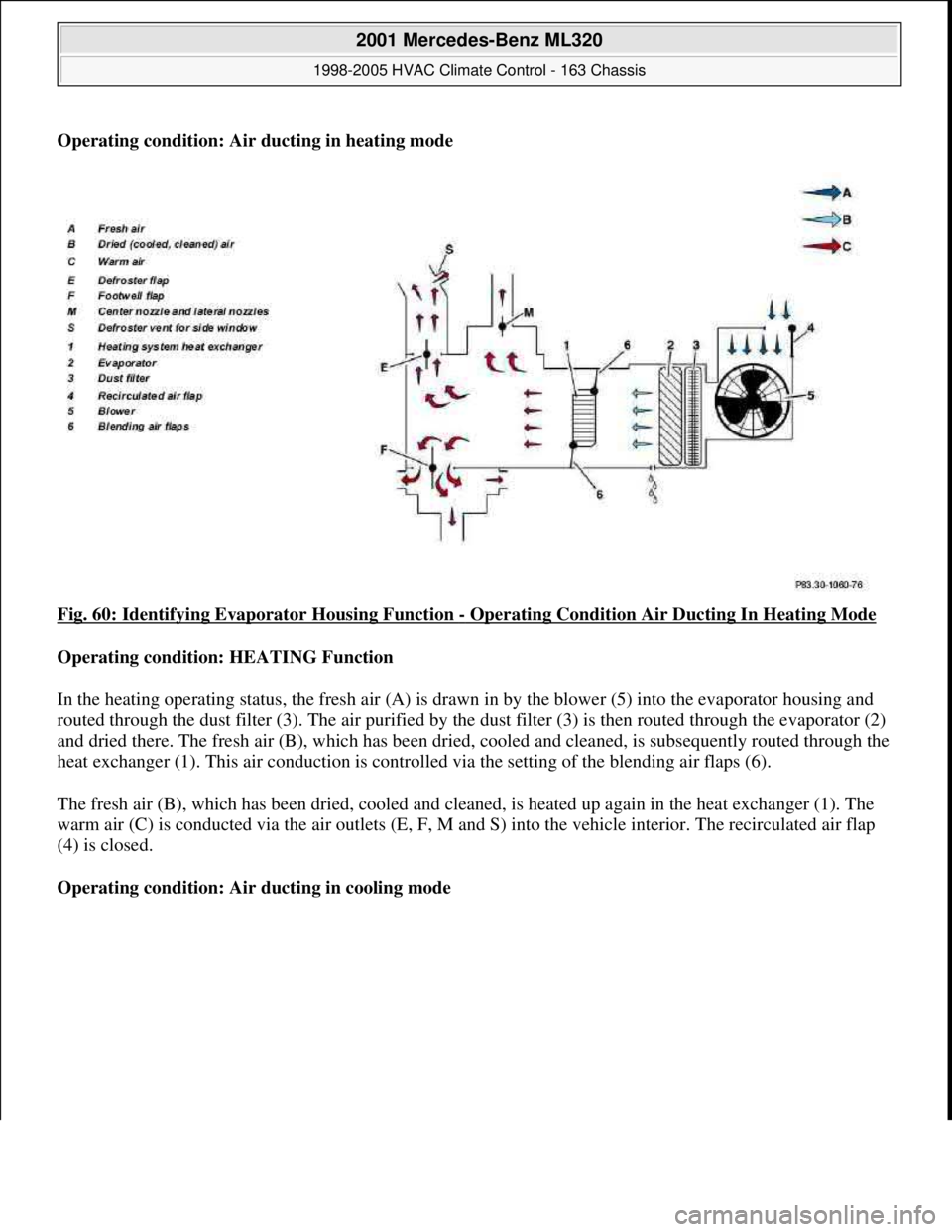
Operating condition: Air ducting in heating mode
Fig. 60: Identifying Evaporator Housing Function
- Operating Condition Air Ducting In Heating Mode
Operating condition: HEATING Function
In the heating operating status, the fresh air (A) is drawn in by the blower (5) into the evaporator housing and
routed through the dust filter (3). The air purified by the dust filter (3) is then routed through the evaporator (2)
and dried there. The fresh air (B), which has been dried, cooled and cleaned, is subsequently routed through the
heat exchanger (1). This air conduction is controlled via the setting of the blending air flaps (6).
The fresh air (B), which has been dried, cooled and cleaned, is heated up again in the heat exchanger (1). The
warm air (C) is conducted via the air outlets (E, F, M and S) into the vehicle interior. The recirculated air flap
(4) is closed.
Operating condition: Air ducting in cooling mode
2001 Mercedes-Benz ML320
1998-2005 HVAC Climate Control - 163 Chassis
me
Saturday, October 02, 2010 3:23:15 PMPage 69 © 2006 Mitchell Repair Information Company, LLC.
Page 3314 of 4133
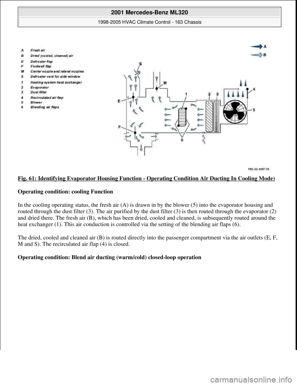
Fig. 61: Identifying Evaporator Housing Function - Operating Condition Air Ducting In Cooling Mode)
Operating condition: cooling Function
In the cooling operating status, the fresh air (A) is drawn in by the blower (5) into the evaporator housing and
routed through the dust filter (3). The air purified by the dust filter (3) is then routed through the evaporator (2)
and dried there. The fresh air (B), which has been dried, cooled and cleaned, is subsequently routed around the
heat exchanger (1). This air conduction is controlled via the setting of the blending air flaps (6).
The dried, cooled and cleaned air (B) is routed directly into the passenger compartment via the air outlets (E, F,
M and S). The recirculated air flap (4) is closed.
Operating condition: Blend air ducting (warm/cold) closed-loop operation
2001 Mercedes-Benz ML320
1998-2005 HVAC Climate Control - 163 Chassis
me
Saturday, October 02, 2010 3:23:15 PMPage 70 © 2006 Mitchell Repair Information Company, LLC.
Page 3315 of 4133
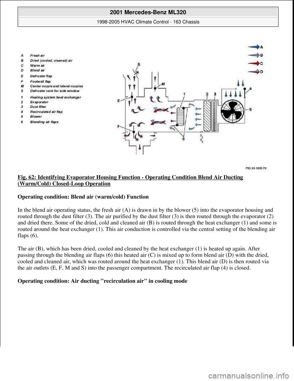
Fig. 62: Identifying Evaporator Housing Function - Operating Condition Blend Air Ducting
(Warm/Cold) Closed-Loop Operation
Operating condition: Blend air (warm/cold) Function
In the blend air operating status, the fresh air (A) is drawn in by the blower (5) into the evaporator housing and
routed through the dust filter (3). The air purified by the dust filter (3) is then routed through the evaporator (2)
and dried there. Some of the dried, cold and cleaned air (B) is routed through the heat exchanger (1) and some is
routed around the heat exchanger (1). This air conduction is controlled via the central setting of the blending air
flaps (6).
The air (B), which has been dried, cooled and cleaned by the heat exchanger (1) is heated up again. After
passing through the blending air flaps (6) this heated air (C) is mixed up to form blend air (D) with the dried,
cooled and cleaned air, which was routed around the heat exchanger (1). This blend air (D) is then routed via
the air outlets (E, F, M and S) into the passenger compartment. The recirculated air flap (4) is closed.
Operating condition: Air ducting "recirculation air" in cooling mode
2001 Mercedes-Benz ML320
1998-2005 HVAC Climate Control - 163 Chassis
me
Saturday, October 02, 2010 3:23:15 PMPage 71 © 2006 Mitchell Repair Information Company, LLC.
Page 3316 of 4133
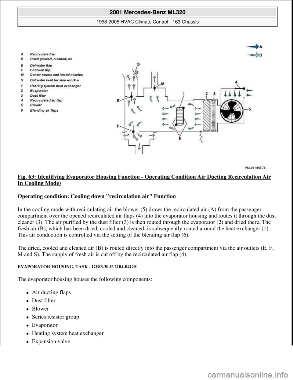
Fig. 63: Identifying Evaporator Housing Function - Operating Condition Air Ducting Recirculation Air
In Cooling Mode)
Operating condition: Cooling down "recirculation air" Function
In the cooling mode with recirculating air the blower (5) draws the recirculated air (A) from the passenger
compartment over the opened recirculated air flaps (4) into the evaporator housing and routes it through the dust
cleaner (3). The air purified by the dust filter (3) is then routed through the evaporator (2) and dried there. The
fresh air (B), which has been dried, cooled and cleaned, is subsequently routed around the heat exchanger (1).
This air conduction is controlled via the setting of the blending air flap (6).
The dried, cooled and cleaned air (B) is routed directly into the passenger compartment via the air outlets (E, F,
M and S). The supply of fresh air is cut off by the recirculated air flap (4).
EVAPORATOR HOUSING, TASK - GF83.30-P-2104-04GH
The evaporator housing houses the following components:
Air ducting flaps
Dust filter
Blower
Series resistor group
Evaporator
Heating system heat exchanger
Expansion valve
2001 Mercedes-Benz ML320
1998-2005 HVAC Climate Control - 163 Chassis
me
Saturday, October 02, 2010 3:23:15 PMPage 72 © 2006 Mitchell Repair Information Company, LLC.
Page 3320 of 4133
The liquefied refrigerant is routed under pressure into the fluid reservoir and flows through a stainless steel
meshing to the filter block. The pores in the filter block are matched precisely to the refrigerant's molecular size.
Thus the refrigerant can flow through the filter block.
All other matter, primarily water, is held back by this molecular filter and deposited. The cleaned refrigerant
flows over a rising pipe to the expansion valve.
Whenever the system is opened, the fluid reservoir should be replaced because of the water which has
collected there in the meantime.
ALL-ACTIVITY MODULE, LOCATION - GF83.30-P-2108-02GH
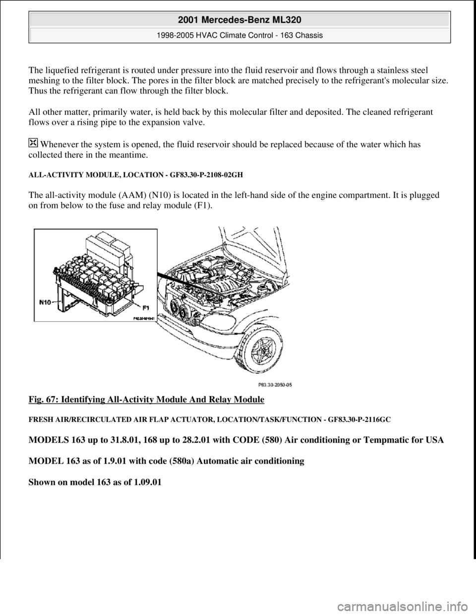
The all-activity module (AAM) (N10) is located in the left-hand side of the engine compartment. It is plugged
on from below to the fuse and relay module (F1).
Fig. 67: Identifying All
-Activity Module And Relay Module
FRESH AIR/RECIRCULATED AIR FLAP ACTUATOR, LOCATION/TASK/FUNCTION - GF83.30-P-2116GC
MODELS 163 up to 31.8.01, 168 up to 28.2.01 with CODE (580) Air conditioning or Tempmatic for USA
MODEL 163 as of 1.9.01 with code (580a) Automatic air conditioning
Shown on model 163 as of 1.09.01
2001 Mercedes-Benz ML320
1998-2005 HVAC Climate Control - 163 Chassis
me
Saturday, October 02, 2010 3:23:15 PMPage 76 © 2006 Mitchell Repair Information Company, LLC.
Page 3322 of 4133
AIR CONDITIONING FLUID RESERVOIR, LOCATION/TASK/FUNCTION - GF83.30-P-2120GC
MODELS 163 up to 31.8.01
168 up to with code (580) Air conditioning or Tempmatic for USA
OVERVIEW OF AIR CONDITIONING (TAC) SYSTEM COMPONENTS, LOCATION/PURPOSE/DESIGN/FUNCTION -
GF83.30-P-9999GI
MODEL 163 up to 31.8.01 with CODE (580a) Automatic air conditioning
Evaporator housing, task 04GH
Evaporator housing,
function GF83.30-P-2104-
02GH
At maximum heating mode in vehicles with engine
612.963 onlyGF83.30-P-2104-
02GK
Fluid reservoir (TAC),
locationModel 168GF83.30-P-2106-
01GC
Model 163GF83.30-P-2106-
01GH
Fluid reservoir (TAC),
task
Filtering chemical and mechanical impurities out
of the refrigerant
Volume accumulator for refrigerant
Draining of refrigerant
Fluid reservoir (TAC),
function GF83.30-P-2106-
02GC
Air inlet, location/function GF83.10-P-
2138GC
Air ducts, location/purpose/design GF83.10-P-
2139GH
Blower, location/purpose/design/function GF83.10-P-
2102GC
Series resistor group, location/purpose/function GF83.10-P-
2161GC
Dust filter, location/purpose/function GF83.10-P-
2142GH
Rear vent, location/purpose/function GF83.10-P-
2143GC
Defroster vent, location/purpose/function GF83.10-P-
2144GC
Center nozzle, location/purpose/function GF83.10-P-
2149GC
2001 Mercedes-Benz ML320
1998-2005 HVAC Climate Control - 163 Chassis
me
Saturday, October 02, 2010 3:23:15 PMPage 78 © 2006 Mitchell Repair Information Company, LLC.