Page 3964 of 4133
1
Phone Overview
The phone uses the vehicle’s integrated antenna when connected via the coilcord.
Earpiece
Headset Jack
Insert headset accessory
for hands-free use.
Status LightSee incoming call and service status.
Volume KeysAdjust earpiece and ringer volume.
Accessory Connector PortInsert charger and phone accessories.
Right Soft KeyPerform functions identified by
right display prompt.
Menu Key
Scroll Key
Move through menus and lists.Power Key
Microphone Voice Key
Record voice notes, phonebook and
shortcut names.
Send KeySend and answer calls, view
recent dialed calls list.
Smart KeySelect menu items, send and end calls.
End KeyEnd phone calls, exit menu system.
Left Soft KeyPerform functions identified by
left display prompt.
Display
Page 3988 of 4133
AD54.30-P-3000-02A
Warning buzzer function check IC
Warning buzzer
D
Light reminder and parking brake reminder
D
Key reminder
I
D
Seat belt reminder
for approx. 6 s
I
,
M
,
H
and Korea
for approx. 12 s
G
The warning tone is interrupted as soon as the seat belt buckle is
inserted.
D
Warning tone for a shortage of oil
D
Vehicle speed warning
G
> 120 km/h, v-limit warning (cruise
control)
D
In addition the symbol for vehicle speed warning appears in the
instrument cluster with multi-function display.
D
On model 163 a warning tone sounds for approx. 5 seconds if the
CAN signal is unusable.
D
Model 168 with automatic clutch system features an audible gear
warning.
It sounds if a gear is engaged at the same time as the driver's
door is opened. Brake and accelerator pedal must not be
operated.
Copyright DaimlerChrysler AG 05.06.2006 CD-Ausgabe G/10/04 . This WIS print-out will not be recorde
d by Modification services.
Page 1
Page 3991 of 4133

AR40.10-P-1040A
Balance wheels
27.1.95
MODELS
124, 129, 140, 163, 168, 170, 171, 202, 203, 208, 209, 210, 211, 215, 220, 230, 240
MODEL
414
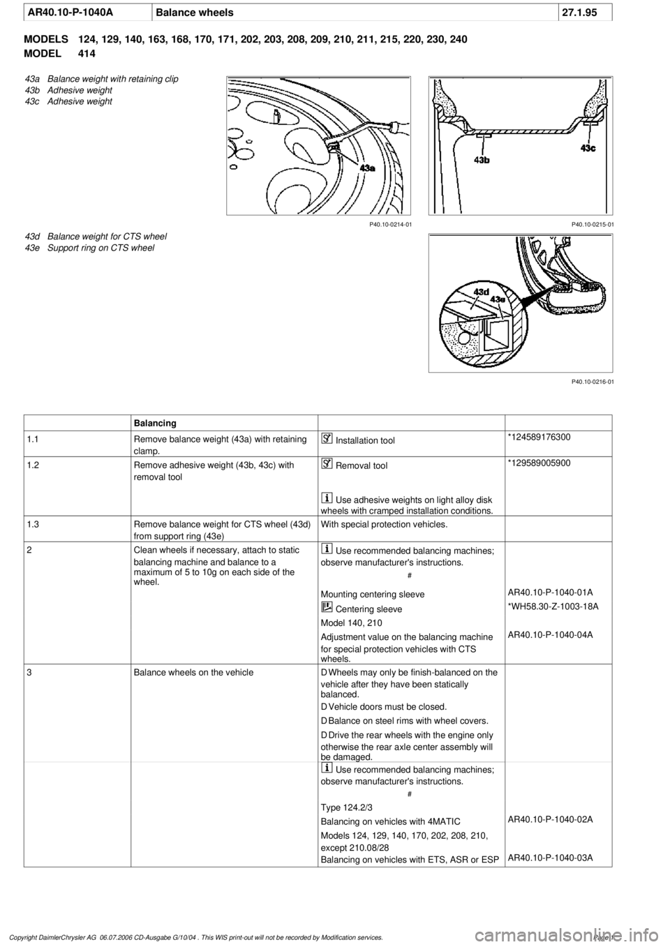
P40.10-0214-01
43a
Balance weight with retaining clip
43b
Adhesive weight
43c
Adhesive weight
P40.10-0215-01
P40.10-0216-01
43d
Balance weight for CTS wheel
43e
Support ring on CTS wheel
Balancing
1.1
Remove balance weight (43a) with retaining
clamp.
Installation tool
*124589176300
1.2
Remove adhesive weight (43b, 43c) with
removal tool
Removal tool
*129589005900
Use adhesive weights on light alloy disk
wheels with cramped installation conditions.
1.3
Remove balance weight for CTS wheel (43d)
from support ring (43e)
With special protection vehicles.
2
Clean wheels if necessary, attach to static
balancing machine and balance to a
maximum of 5 to 10g on each side of the
wheel.
Use recommended balancing machines;
observe manufacturer's instructions.
#
Mounting centering sleeve
AR40.10-P-1040-01A
Centering sleeve
*WH58.30-Z-1003-18A
Model 140, 210
Adjustment value on the balancing machine
for special protection vehicles with CTS
wheels.
AR40.10-P-1040-04A
3
Balance wheels on the vehicle
D
Wheels may only be finish-balanced on the
vehicle after they have been statically
balanced.
D
Vehicle doors must be closed.
D
Balance on steel rims with wheel covers.
D
Drive the rear wheels with the engine only
otherwise the rear axle center assembly will
be damaged.
Use recommended balancing machines;
observe manufacturer's instructions.
#
Type 124.2/3
Balancing on vehicles with 4MATIC
AR40.10-P-1040-02A
Models 124, 129, 140, 170, 202, 208, 210,
except 210.08/28
Balancing on vehicles with ETS, ASR or ESP
AR40.10-P-1040-03A
Copyright DaimlerChrysler AG 06.07.2006 CD-Ausgabe G/10/04 . This WIS print-out will not be recorde
d by Modification services.
Page 1
Page 3993 of 4133
AR40.10-P-1010-01A
Checking condition of rim
P40.10-0259-01
1
Check inside and outside of wheel for dirt and clean wheel if necessary.
2
Check contact surface of rim for dirt and clean if necessary.
3
Check centering, spherical caps and rim flanges for damage. The spherical caps must be
free of grease.
Light-alloy rims
4
The rim flanges on light-alloy rims may exhibit increased levels of wear under the following
conditions:
High loads, operation with a trailer, insufficient tire inflation pressure, use of non-approved
tire makes or versions, contamination with dirt, sand and road salt.
5
The wear (X) must be no more than 1 mm.
Copyright DaimlerChrysler AG 06.07.2006 CD-Ausgabe G/10/04 . This WIS print-out will not be recorde
d by Modification services.
Page 1
Page 4035 of 4133
Fig. 18: 3.2L, Engine Performance Circuit (3 of 3)
EXTERIOR LIGHTS
2001 Mercedes-Benz ML320
2001 SYSTEM WIRING DIAGRAMS Mercedes-Benz - ML320
me
Saturday, October 02, 2010 3:27:59 PMPage 37 © 2006 Mitchell Repair Information Company, LLC.
Page 4039 of 4133
Fig. 20: Exterior Lights Circuit (1 of 2)
2001 Mercedes-Benz ML320
2001 SYSTEM WIRING DIAGRAMS Mercedes-Benz - ML320
me
Saturday, October 02, 2010 3:27:59 PMPage 41 © 2006 Mitchell Repair Information Company, LLC.
Page 4041 of 4133
Fig. 21: Exterior Lights Circuit (2 of 2)
GROUND DISTRIBUTION
2001 Mercedes-Benz ML320
2001 SYSTEM WIRING DIAGRAMS Mercedes-Benz - ML320
me
Saturday, October 02, 2010 3:27:59 PMPage 43 © 2006 Mitchell Repair Information Company, LLC.
Page 4047 of 4133
Fig. 24: Ground Distribution Circuit (3 of 3)
HEADLIGHTS
2001 Mercedes-Benz ML320
2001 SYSTEM WIRING DIAGRAMS Mercedes-Benz - ML320
me
Saturday, October 02, 2010 3:27:59 PMPage 49 © 2006 Mitchell Repair Information Company, LLC.