1997 MERCEDES-BENZ ML350 light
[x] Cancel search: lightPage 3834 of 4133

463
All
-----
1)
Recognition: existing "airbag Off" warning light in center
console.
2)
With HHT functions menu point 5 Coding Reboard child seat. If
only the passenger side airbag is de-activated, then program
menu point Vehicle equipment.
3)
Depending on model and version, unplug one or two
connectors at the passenger side airbag and insert the
corresponding replacement resistors.
4)
Without ACSR, with seat belt force limiter.
Immobilizing passenger side airbag certificate
Model 124, 126, 129, 140, 163 up to VIN
145263, 170, 202, 210
Have customer sign certificate after
immobilization
OF91.60-P-1000-01A
Cancel immobilization
D
To re-activate the passenger side airbag remove the ignition
resistor at the cable.
D
Fit together connector at passenger side airbag.
D
Fit together connector at passenger side ETR (on models fitted
with seat belt force limiter).
D
Use HHT or STAR Diagnosis tool (DAS) to re-program
passenger side airbag and passenger side ETR in the SRS
control module to "YES".
D
Remove sticker on passenger side airbag and render invalid in
Owner's Manual.
D
Complete re-activation on certificate after immobilization.
D
If re-activated, delete de-activation in vehicle documents.
Parts ordering notes
Part no.
Designation
Quantity
140 868 00 50
Ignition resistor (replacement resistor)
as required
140 817 15 20
Sticker (without seat belt force limiter)
2
210 817 20 20
Sticker (with seat belt force limiter)
2
Copyright DaimlerChrysler AG 14.06.2006 CD-Ausgabe G/10/04 . This WIS print-out will not be recorde
d by Modification services.
Page 2
Page 3836 of 4133

Measures for slightly sludged engine:
Oil and filter change. Purge engine, i.e. normal engine operation
in neutral, or while driving, using oil from Sheet 229.3, 228.3, or
228.5. Drain off scavenging oil after purging process (approx. 1
hour). Repeat purging process if necessary. Refill using engine oil
from Sheet 229.3, or 229.1. The first oil change after clearing the
sludge should be performed after approx. 10,000 km or beforehand;
when doing so use engine oil from Sheet 229.3.
Measures for severely sludged engine:
Engines with severe oil sludging and caking onto engine parts
and into bores have to be dismantled and mechanically cleaned.
Tough sludge residue must not enter the clean side of the oil circuit,
as otherwise, e.g. the piston oil spray and the hydraulic
compensation elements may have their functionality impaired. Refill
using engine oil from Sheet 229.3, or 229.1.
The first oil change after sludging should be performed after approx.
10,000 km; when doing so use engine oil from
Sheet 229.3.
Warranty/goodwill regulations
If in combination with engine oil sludging a warranty/goodwill claim is
submitted, then a regular documentation of maintenance must be
presented. The ASSYST printout is to be filed carefully for further
reference.
Oil sludging in combination with an exceeded oil change interval, or
because of special additives in the fuel/engine oil are costs to be
borne by the customer.
Copyright DaimlerChrysler AG 20.05.2006 CD-Ausgabe G/10/04 . This WIS print-out will not be recorde
d by Modification services.
Page 2
Page 3852 of 4133

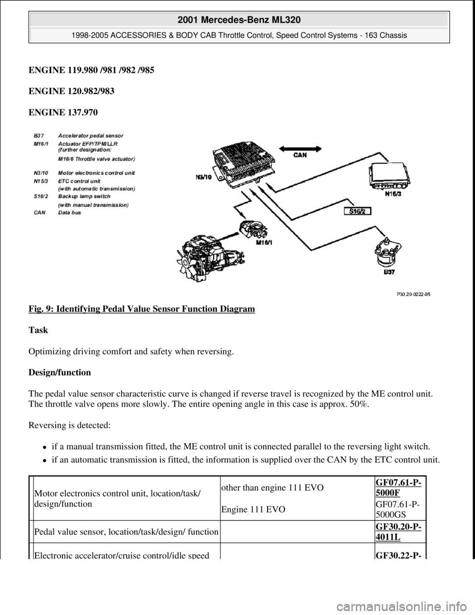
ENGINE 119.980 /981 /982 /985
ENGINE 120.982/983
ENGINE 137.970
Fig. 9: Identifying Pedal Value Sensor Function Diagram
Task
Optimizing driving comfort and safety when reversing.
Design/function
The pedal value sensor characteristic curve is changed if reverse travel is recognized by the ME control unit.
The throttle valve opens more slowly. The entire opening angle in this case is approx. 50%.
Reversing is detected:
if a manual transmission fitted, the ME control unit is connected parallel to the reversing light switch.
if an automatic transmission is fitted, the information is supplied over the CAN by the ETC control unit.
Motor electronics control unit, location/task/
design/functionother than engine 111 EVOGF07.61-P-
5000F
Engine 111 EVOGF07.61-P-
5000GS
Pedal value sensor, location/task/design/ function GF30.20-P-
4011L
Electronic accelerator/cruise control/idle speed GF30.22-P-
2001 Mercedes-Benz ML320
1998-2005 ACCESSORIES & BODY CAB Throttle Control, Speed Control Systems - 163 Chassis
me
Saturday, October 02, 2010 3:36:27 PMPage 12 © 2006 Mitchell Repair Information Company, LLC.
Page 3854 of 4133

ENGINE 113.940 /941 /942 /943 /948 /960 /961 /963 /965 /966 /967 /968 /969
ENGINE 119.980 /981 /982 /985
ENGINE 137.970
Task
To allow safe further driving depending on the fault which has arisen in the electronic accelerator pedal system.
Pedal value sensor emergency mode
If the sensor in the pedal value sensor (B37) fails, the system will switch over to the second sensor. The throttle
valve opening is limited to approx. 60%. There is also dynamic limitation of the throttle valve's opening speed
where the throttle valve opening is delayed (the indicator lamp EPC does not light up).
If the plausibility check delivers a negative result or both sensors are defect only the idling speed will be
regulated (the indicator lamp EPC lights up).
Actuator for the throttle valve - emergency running, electrical
If a potentiometer in the actuator for the throttle valve breaks down the system switches-over to the second
intact potentiometer. The air flow mass serves as a second parameter for comparative purposes. Following a
plausibility check, the throttle valve opening is limited to approx. 60% in line with engine speed and load (EPC
indicator lamp does not come on).
If the plausibility check is negative or if both potentiometers are faulty, the throttle valve adopts a mechanical
emergency running position which is fixed by the spring capsule in the actuator (EPC indicator lamp comes on).
Actuator for the throttle valve - emergency running, mechanical emergency running stop
If the actuator motor is defect or there are other faults present the power supply to the actuator will be shut off.
The throttle valve then lies on the mechanical stop (spring box) so the throttle valve opening remains at a
constant 10-12°. At no engine load (idling) engine speed is regulated to about 900 rpm by shutting off or
activating the cylinders at the fuel side.
When driving, engine speed is controlled, in line with the engine load, by switching the cylinders off and on at
the fuel side. The maximum engine speed is about 1800 rpm. which is limited by the mechanical stop (the
indicator lamp EPC lights up).
Safety fuel shutoff
If a mechanical fault exists in the actuator, the safety fuel shutoff is activated.
Here the fuel injection valves are shut off for engine speeds < 1400 rpm and actuated again at speeds < 1200
rpm (the indicator lamp EPC li
ghts up).
2001 Mercedes-Benz ML320
1998-2005 ACCESSORIES & BODY CAB Throttle Control, Speed Control Systems - 163 Chassis
me
Saturday, October 02, 2010 3:36:27 PMPage 14 © 2006 Mitchell Repair Information Company, LLC.
Page 3900 of 4133

5
Remove key and engage steering lock
6
Unscrew bolt (32c)
Hold the steering wheel (32).
Installation:
Replace bolt (32c).
*BA46.10-P-1001-02A
7
Pull off steering wheel (32)
Pass cables carefully through the openings.
Installation:
Align recesses of the splines
in the steering wheel with the markings on the
steering shaft (arrows).
8
Check fanfare horns and airbag clock spring
contact (A45) for damage
The clock spring contact must not be
turned while the steering wheel is removed
otherwise it will be damaged.
Visual inspection, replace clock spring
contact if necessary:
#
Removing and installing clock spring contact
AR46.10-P-0200GH
9
Install in the reverse order
10
Carry out road test
Tests during the road test:
Turn signal canceling:
When the steering wheel is offset by
more than 1 tooth, satisfactory resetting of the
turn signal is no longer guaranteed.
Airbag indicator lamp:
The SRS indicator lamp must not light up
on full steering lock in both directions.
Steering wheel position:
If the steering wheel is crooked, adjust it
by max. 1 tooth. If the difference is greater:
#
Check toe on front axle and adjust if
necessary, see:
#
Performing chassis alignment check
AR40.20-P-0200A
Steering wheel
Number
Designation
Model 163
BA46.10-P-1001-02A
Bolt, steering wheel to steering shaft
Nm
80
Copyright DaimlerChrysler AG 09.05.2006 CD-Ausgabe G/10/04 . This WIS print-out will not be recorde
d by Modification services.
Page 2
Page 3907 of 4133

AR88.30-P-0200-01GH
Separate detachable body components
Danger!
Risk of poisoning
after inhaling vapors or
swallowing adhesive.
Risk of injury
from
adhesive coming into contact with skin and
eyes
Wear protective respiratory masks,
protective gloves and safety glasses.
Pour adhesive only into suitable and
appropriately marked containers.
AS00.00-Z-0016-01A
Long wedge
115 589 03 59 00
Commercially available tools
(see Workshop Equipment Manual)
Number
Designation
Make (e. g.)
Order number
WH58.30-Z-1010-10A
Cutting tool kit (compressed-air tool + blades)
Europe:
The Barn
Holly Tree Farm
Holmes Chapel Road
Lower Withington,
Cheshire, SK11 9DT
England
Tel.:
+44 1477 571700
Japan:
Osaka Chamber of
Commerce
2-8 Hommachibashi
Chuo-ku
Osaka, Japan, 540-
0029
Tel.:+81 6 6944 6445
USA:
SPX
Dealer Equipment
Services Tel.:
+1-888-458-4040
P88.30-2108-01
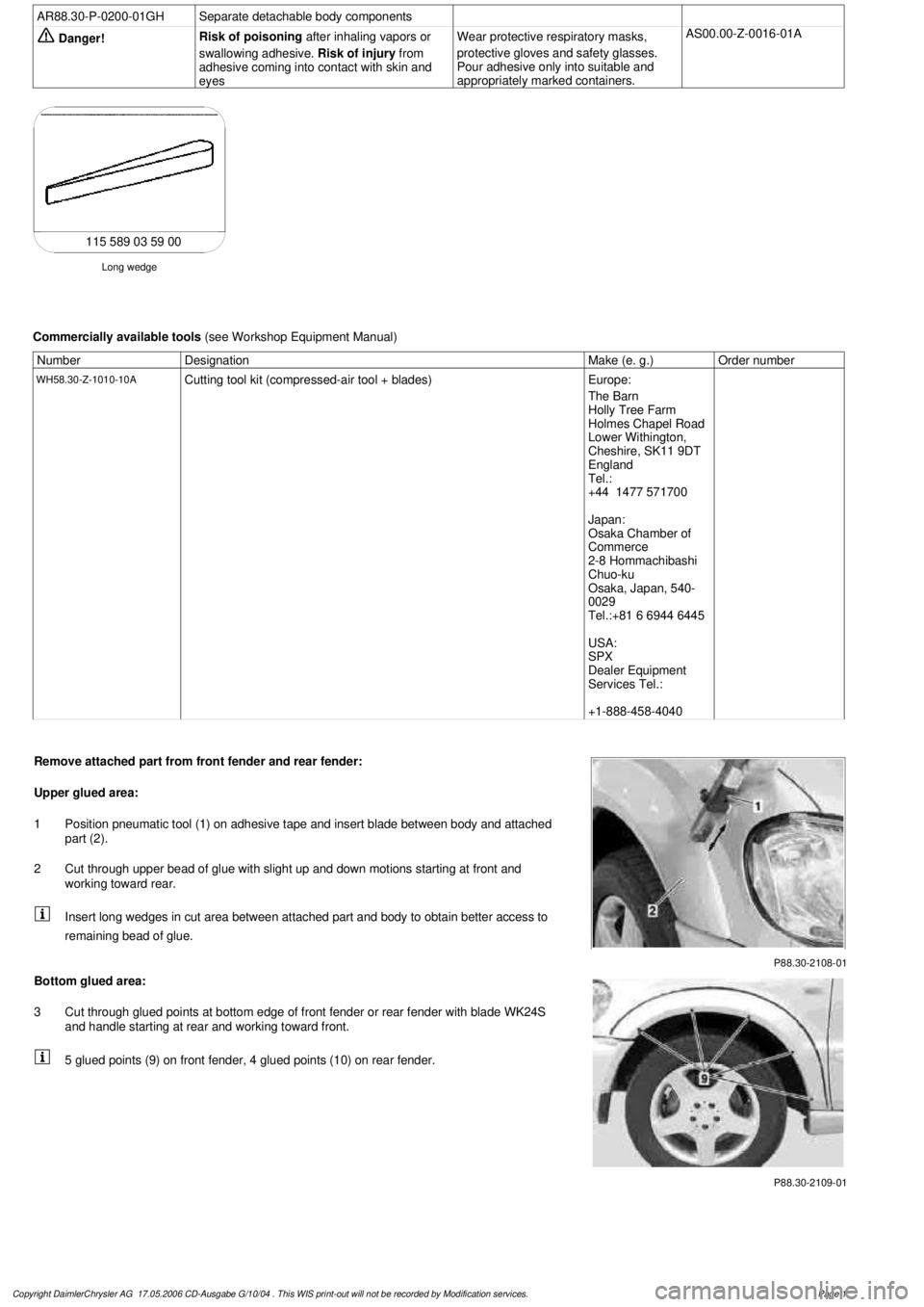
Remove attached part from front fender and rear fender:
Upper glued area:
1
Position pneumatic tool (1) on adhesive tape and insert blade between body and attached
part (2).
2
Cut through upper bead of glue with slight up and down motions starting at front and
working toward rear.
Insert long wedges in cut area between attached part and body to obtain better access to
remaining bead of glue.
P88.30-2109-01
Bottom glued area:
3
Cut through glued points at bottom edge of front fender or rear fender with blade WK24S
and handle starting at rear and working toward front.
5 glued points (9) on front fender, 4 glued points (10) on rear fender.
Copyright DaimlerChrysler AG 17.05.2006 CD-Ausgabe G/10/04 . This WIS print-out will not be recorde
d by Modification services.
Page 1
Page 3908 of 4133

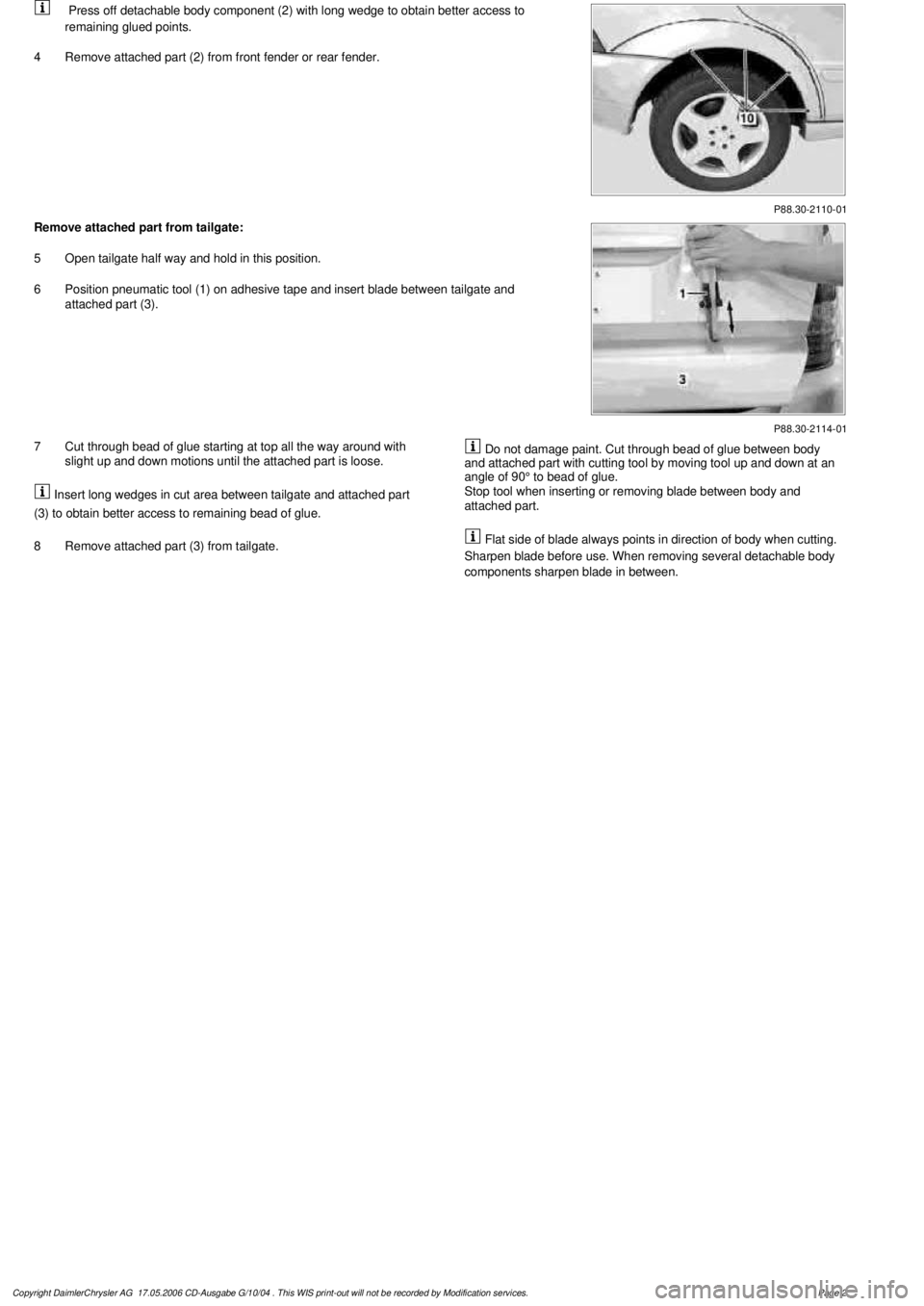
P88.30-2110-01
Press off detachable body component (2) with long wedge to obtain better access to
remaining glued points.
4
Remove attached part (2) from front fender or rear fender.
P88.30-2114-01
Remove attached part from tailgate:
5
Open tailgate half way and hold in this position.
6
Position pneumatic tool (1) on adhesive tape and insert blade between tailgate and
attached part (3).
7
Cut through bead of glue starting at top all the way around with
slight up and down motions until the attached part is loose.
Insert long wedges in cut area between tailgate and attached part
(3) to obtain better access to remaining bead of glue.
8
Remove attached part (3) from tailgate.
Do not damage paint. Cut through bead of glue between body
and attached part with cutting tool by moving tool up and down at an
angle of 90° to bead of glue.
Stop tool when inserting or removing blade between body and
attached part.
Flat side of blade always points in direction of body when cutting.
Sharpen blade before use. When removing several detachable body
components sharpen blade in between.
Copyright DaimlerChrysler AG 17.05.2006 CD-Ausgabe G/10/04 . This WIS print-out will not be recorde
d by Modification services.
Page 2
Page 3960 of 4133

AD54.30-P-5000-03A
Directly controlled display instruments
troubleshooting chart IC
Directly controlled display instruments or indicator
lamp/warning message:
D
Outside temperature indicator
D
Fuel gauge
D
Oil pressure gauge (models 129 and 140 only)
D
Left turn signal indicator lamp
D
Right turn signal indicator lamp
D
High beam indicator lamp
D
Fuel reserve indicator lamp
D
Airbag SRS indicator lamp/MIL
D
AIRBAG OFF indicator lamp (only model 163 except
I )
D
Low brake fluid level/parking brake indicator lamp (only brake
fluid direct)
(both functions via CAN on model 163)
D
Low windshield washer fluid level indicator lamp (except
models 163 and 168)
D
Low ECL indicator lamp (except models 163 and 168)
D
Generator charge indicator lamp
D
Seat belt reminder lamp
D
Seat belt/backrest lock reminder lamp
D
Exterior lamp failure indicator lamp
D
Hydraulic fluid level indicator lamp (models 202 and 210 only)
D
ADS MIL, suspension
D
Turn signal clicking
D
Seat belt reminder lamp
D
Light reminder lamp
D
Key reminder lamp
D
Soft top reminder lamp (model 170 only)
D
Steering lock warning lamp (
I )
Copyright DaimlerChrysler AG 05.06.2006 CD-Ausgabe G/10/04 . This WIS print-out will not be recorde
d by Modification services.
Page 1