1997 MERCEDES-BENZ ML350 oil change
[x] Cancel search: oil changePage 3176 of 4133

Because the brake fluid also absorbs moisture through the vent bore on the expansion reservoir, the wheel brake
cylinder and the brake hoses, the brake fluid has to be changed for safety reasons at regular intervals, best done
in the spring. When performing this change, make sure that the old fluid is also drained off the clutch system.
Generally, it is vital for the brake/clutch system to be completely drained before being filled with new fluid!
For the above-mentioned reasons, used brake fluid must not be used again.
The brake fluid is amber in color and thus can be easily confused with mineral products.
Therefore, brake fluids should always only be taken from original containers and stored separately from other
mineral oils and fluids.
When performing maintenance operations and repairs on brake parts, make sure that fuel, mineral oil, grease or
suchlike do not enter the brake system. Hydrocarbon-based materials will lead to swelling of the elastomers in
the brake and clutch system and - even in low concentrations - will suffice to cause total failure of the systems.
Only new brake fluid may be used as a rinsing and cleaning agent for the cylinders, lines and the expansion
reservoir of the hydraulic brake system.
Experience shows that before handling brake fluid, the hands must be cleaned and any oil and grease removed.
Brake fluid acts aggressively towards paint and color. In the event of any brake fluid spills or splashes, it must
be rinsed away immediately using copious amounts of water (do not rub it away).
Brake fluid disposal
When disposing of brake fluid, the relevant national specifications must be observed. It is advisable to try to
have the brake fluid disposed of as economic good; this is contingent on
Strict separation of used brake fluid from other materials;
Presence of a disposal channel, which justifies its classification as an economic good, i.e. a proper
alternate usage must be assured.
If this procedure is not possible, used brake fluid is to be disposed of together with any, e.g. paint residue,
solvents and suchlike. Any adding of used oil must be avoided, as it will result in difficulties, if the used oil is to
be recycled; in several countries this is prohibited by the legislators.
MISCELLANEOUS NOTES
NOTES ON SCRAPPING GAS-FILLED HYDRAULIC COMPONENTS - OS00.00-P-1000-01A
all
Unusable gas pressure dampers, spring accumulators, pressure reservoirs and impact absorbers have to be
depressurized before being scrapped according to the respective valid accident prevention regulations. These
safety measures are necessary because gas pressurized hydraulic parts can explode if heat is applied. A risk of
explosion is
given, e.g. when scrapping with cutting torches, smelting or if gas pressurized parts in landfills start
2004 Mercedes-Benz ML350
1998-2005 GENINFO Overall vehicle - 163 Chassis
me
Saturday, October 02, 2010 3:47:57 PMPage 531 © 2006 Mitchell Repair Information Company, LLC.
Page 3185 of 4133

AD54.30-P-2000-02GC
Notes on HHT previous knowledge diagnosis
IC
HHT :
The instrument cluster and active service system (ASSYST) sub-
function are checked with HHT, there being the choice of the
following functions for this:
1. Control module version
2. Fault memory
3. Actual values
4. Actuations
5. Control module adaptation
Additional information on test items 2, 3 and 5 can be called up using
the INPUT key
Control module adaptation
The following alternatives are available in the HHT under control
module adaptation:
1.)
Read out coding and transfer to new instrument cluster. IC and
ASSYST.
2.)
Read out/change codings e.g.:
Engine and national variants,
version of fuel tank,
special equipment etc.
3.)
Settings:
1
Clock
2
Put forward kilometer reading
3
Put back kilometer reading
4
Oil change
5
Reset oil change initiated inadvertently
6
Active Service System
7
Enter times with battery disconnected
8
Set minimum oil warning
Before replacing a defective instrument cluster, readout the existing
variant codings (driving data and instrument cluster data) and store in
the HHT on an interim basis. Read in the values stored on an interim
basis again after installing the new instrument cluster.
If it is not possible to read out the stored variant coding, all variant
codings must be input manually (menu-assistance in HHT).
When installing an instrument cluster on an experimental basis, do
not put forward the kilometer reading as it cannot be put back later.
Copyright DaimlerChrysler AG 05.06.2006 CD-Ausgabe G/10/04 . This WIS print-out will not be recorde
d by Modification services.
Page 1
Page 3191 of 4133

Valve seal not okay :
#
3
Remove/install/replace valve seal.
AR05.30-P-3500B
Cause 6:
Remedy 6:
00 001 70
1.5 mm hole missing on individual right
cylinder head covers at connection to
crankcase ventilation.
1
Check cylinder head cover
Up to production 06/1999.
Crankcase ventilation out of order, engine can
sludge up and consume oil as a result
Cylinder head cover not okay:
#
2
Remove/install/replace cylinder head
cover.
ENGINE
112
Air cleaner positioned on engine
side.
ENGINE
113
Air cleaner positioned on engine
side.
AR01.20-P-5014BV
ENGINE
112
Air cleaner positioned on engine side
ENGINE
113
Air cleaner positioned on engine side
AR01.20-P-5014B
Cause 7:
Remedy 7:
00 001 70
Engine oil sludging due to excessively long
engine oil change intervals
Service information: Oil sludge
SI18.00-P-0010A
If the service interval according to
ASSYST is exceeded, the engine oil sludges
up sooner or later depending on the oil
quality, type of operation and operating time.
Engine consumes oil.
See Service Information.
1
Print out ASSYST printout.
2
Check oil change intervals
3
Inform vehicle owner.
4
Remove/install/replace piston rings.
AR03.10-P-7311BV
Disassemble and clean sludged engines
completely because dirty oil usually gets into
clean-oil side due to clogged oil filter.
Cause 8:
Remedy 8:
00 001 70
Piston rings sticky or have coke deposits from
engine oils (e.g. API-S in USA) in connection
with regionally poor fuel quality.
Always use engine oils according to
Specifications for Operating Fluids 229.3, do
not add special additives to engine oil and fuel
BB00.40-P-0229-03A
1
Remove/install/replace piston rings.
AR03.10-P-7311BV
Cause 9:
Remedy 9:
00 001 70
Piston ring wear due to excessive
contamination/dust (model 163) through air
intake system.
1
Remove/install/replace gaskets on air
intake line and distribution element of
partial load ventilation.
e.g. due to incorrect assembly after
workshop visit or embrittlement of gaskets
The distribution element with optimized
material will be available as of 11/ 2000 as a
standard feature.
2
Remove/install/replace intake module.
Exterior oil loss, e.g. due to cast iron
porosity on left side of crankcase in area of
engine support is not considered to be oil
consumption
In the event of a customer complaint
regarding the engine oil consumption, always
determine the oil consumption definitely
because the oil indicator lamp can come on
due to other causes (e.g. defective oil sensor).
Commercially available tools
(see Workshop Equipment Manual)
Number
Designation
Make (e. g.)
Order number
WH58.30-Z-1009-05A
Flexible inspection light
Scope of supply 1 (complete unit):
-glass fiber optical fiber
-light projector
-230 V, storage case
-operating instructions
-graphics protocol
Richard Wolf GmbH
Pforzheimerstr. 32
D-75438 Knittlingen
Karl Storz GmbH
Mittelstr. 8
D-78532 Tuttlingen
1.00565.00
80902
WH58.30-Z-1010-05A
Flexible inspection light
Scope of delivery 2 (for workshops which already have an approved
Wolf or Storz inspection light):
-storage case
-operating instructions
-pictures protocol
Richard Wolf GmbH
Pforzheimerstr. 32
D-75438 Knittlingen
Karl Storz GmbH
Mittelstr. 8
D-78532 Tuttlingen
7.05065.00
K03506AJ
Copyright DaimlerChrysler AG 20.05.2006 CD-Ausgabe G/10/04 . This WIS print-out will not be recorde
d by Modification services.
Page 2
Page 3369 of 4133

Diaphragm pressure in the refrigerant compressor control valve (8) (approx. 2 bar)
Suction pressure of refrigerant compressor
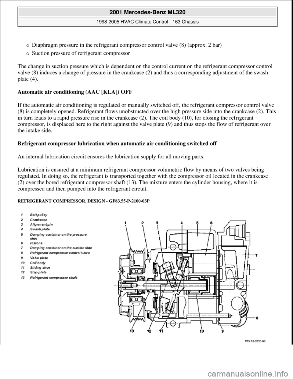
The change in suction pressure which is dependent on the control current on the refrigerant compressor control
valve (8) induces a change of pressure in the crankcase (2) and thus a corresponding adjustment of the swash
plate (4).
Automatic air conditioning (AAC [KLA]) OFF
If the automatic air conditioning is regulated or manually switched off, the refrigerant compressor control valve
(8) is completely opened. Refrigerant flows unobstructed over the high pressure side into the crankcase (2). This
in turn leads to a rapid pressure rise in the crankcase (2). The coil body (10), for closing the refrigerant
compressor, is displaced here to the right against the valve plate (9) and thus stops the flow of refrigerant over
the intake side.
Refrigerant compressor lubrication when automatic air conditioning switched off
An internal lubrication circuit ensures the lubrication supply for all moving parts.
Lubrication is ensured at a minimum refrigerant compressor volumetric flow by means of two valves being
regulated. In doing so, the refrigerant is transported together with the compressor oil located in the crankcase
(2) over the bored refrigerant compressor shaft (13). The mixture enters the cylinder housing, where it is
compressed and then pumped into the refrigerant circuit.
REFRIGERANT COMPRESSOR, DESIGN - GF83.55-P-2100-03P
2001 Mercedes-Benz ML320
1998-2005 HVAC Climate Control - 163 Chassis
me
Saturday, October 02, 2010 3:23:16 PMPage 125 © 2006 Mitchell Repair Information Company, LLC.
Page 3441 of 4133

poisoning from swallowing
coolant.Wear protective gloves, protective
clothing and eye protection.
1Drain coolantEngine 111 in MODEL 163.AR20.00-P-
1142HG
Engines 112 /113 in MODEL 163.AR20.00-
P-1142HA
Engine 628.963 in MODEL 163.128.AR20.00-P-
1142HB
Engine 612.963 in MODEL 163.113.AR20.00-P-
1142M
2.1 Detach
brake line
from the
front end of
the radiator
Only required for right-hand steering.
3.1 Detach
ignition
cable from
the front end
of the
radiator
Only required on right-hand drive vehicles
with ENGINES 111 /112/113.
4Release coolant overflow from
battery shield
5Disconnect upper coolant hose
from the electric coolant pump Detach hose clamp from the upper
coolant hose.
6Unscrew nuts from expansion
reservoir at firewall
7Remove expansion reservoir from
the firewall and lay aside
8Disconnect coolant delivery/return
hoses for heat exchanger (17) Detach hose clamps from coolant
delivery/ return hoses for heat exchanger.
9Discharge air conditioning system
Installation: Evacuate air
conditioning, refill and check for proper
operation and leaktightness.AR83.30-
P-1760GH
10Unscrew self-locking nut (16) at
the expansion valve (15) Replace self-locking nut.
*BA83.30-
P-1003-01B
11
Detach low-pressure refrigerant
line (13) and high-pressure
refrigerant line (14) from expansion
valve (15)
Installation: Install new sealing rings
and moisten with compressor oil.
12Remove instrument panel carrier
(4) AR68.10-
P-1111GH
2001 Mercedes-Benz ML320
1998-2005 HVAC Climate Control - 163 Chassis
me
Saturday, October 02, 2010 3:23:18 PMPage 197 © 2006 Mitchell Repair Information Company, LLC.
Page 3464 of 4133

Remove/install
Risk of injury to skin and eyes
suffering scalding from contact with
hot coolant spray. Risk of poisoning
from swallowing coolant.
Do not open cooling system unless coolant
temperature is below 90°C. Open cap slowly
and release the pressure. Do not pour
coolant into beverage bottles.
Wear protective gloves, protective clothing
and eye protection.
AS20.00-Z-
0001-01A
Risk of explosion from welding or
soldering work on closed air
conditioning system. Risk of
poisoning. Inhaling overheated
refrigerant vapors may be toxic. Risk
of injury from skin and eye contact
with liquid refrigerant.Do not carry out any welding work on the
closed air conditioning system or in the
surrounding area. No smoking or open
flames. Wear eye protection and protective
gloves. Work only in well ventilated areas.
Carry out repair work on the air
conditioning system circuit only after the
system has been discharged.
AS83.00-Z-
0001-01A
Procedures if air conditioning system
is damaged or leakingAll models
AH83.30-
N-0004-
01A
Protect air conditioning circuit and
components from moisture when
carrying out repair work
All models fitted with air conditioning
AH83.30-
N-0005-
01A
Notes on handling refrigerant R134aAll models fitted with air conditioning
AH83.30-
N-0003-
01A
1Drain coolant J Engine 112, 113.AR20.00-P-
1142HA
Engine 111.AR20.00-P-
1142HG
Engine 612.963.AR20.00-P-
1142M
2Unscrew coolant compensating
reservoir (1) on firewall Lay compensating reservoir to one side.
3Disconnect coolant delivery/return
hoses for heat exchanger (2) Remove hose clamps from coolant hoses.
4Discharge air conditioning system
Installation: Evacuate air conditioning,
refill and check for proper operation and
leaktightness.AR83.30-P-
1760GH
5Remove cover on expansion valve
(4)
6Remove nut (3) on expansion valve
(4) Replace self-locking nut.
*BA83.30-
P-1003-01B
7Disconnect refrigerant lines from
expansion valve Installation: Install new sealing rings
and moisten with compressor oil.
2001 Mercedes-Benz ML320
1998-2005 HVAC Climate Control - 163 Chassis
me
Saturday, October 02, 2010 3:23:19 PMPage 220 © 2006 Mitchell Repair Information Company, LLC.
Page 3479 of 4133

BT27.00-Z-9999AZ
Technical modifications: Passenger cars: Automatic transmission
30.4.97
MODEL all
Vacuum unit for modulating pressure modified
TRANSMISSION 722.3 /5 as of 15.8.92
BT27.10-P-0001-01A
Secondary pump dispensed with
TRANSMISSION 722.5## ## as of 3652931
BT27.10-P-0002-01A
Control pressure cable with vacuum actuators
standardized
TRANSMISSION 722.3 /4 /5 as of 1.7.93
BT27.10-P-0003-01A
Sump volume modified
TRANSMISSION 722.7## ## as of 0054011
as of 29.7.99
BT27.10-P-0004-01A
Additional shim between deep-groove ball
bearing and output flange
TRANSMISSION 722 ...
BT27.10-P-0005-01A
Oil pan and overflow tube modified
TRANSMISSION 722.901
BT27.10-P-0006-01W
Retaining lug added to electrohydraulic
control module
TRANSMISSION 722.6## # as of 0026195
BT27.19-P-0001-01A
Caps for solenoid valve, new
TRANSMISSION 722.6 as of 1.8.97
BT27.19-P-0003-01A
Oil drain plug on torque converter deleted
TRANSMISSION 722.6## /6## ## as of
1772285 as of 22.9.99
BT27.20-P-0001-01A
Small intermediate plate modified
TRANSMISSION 722.5## ## as of 3987361
as of 15.3.94
BT27.35-P-0001-01A
Installation of a pressure feed valve
TRANSMISSION 722.6## # as of 0027083
BT27.35-P-0002-01A
Primary pump non-return valve dispensed with
TRANSMISSION 722.5## ## as of 3652931
BT27.35-P-0003-01A
Strainer for modulating pressure and shift
pressure control solenoid valve, new
TRANSMISSION 722.6## ## as of 0538312
BT27.35-P-0004-01A
Strainer in inlet to converter lock-up control
solenoid valve, newTRANSMISSION 722.6## ## as of 0485895
BT27.35-P-0005-01A
Feed B1 enlarged
TRANSMISSION 722.5 as of 15.8.91
BT27.40-P-0001-01A
Fluid reservoir deleted
TRANSMISSION 722.7## ## as of 0111673
as of 11.9.00
BT27.40-P-0002-01A
Magnet in oil pan, new part
TRANSMISSION 722.6## ## as of 2871384
as of 17.4.01, 722.7## ## as of 0153700 as
of 9.7.01
BT27.40-P-0003-01A
Piston B1 modified
TRANSMISSION 722.5## ## as of 3746852
as of 15.6.92, 722.3## ## as of 3969172
BT27.50-P-0002-01A
Plain bearing of input shaft changed to an anti-
friction bearing
TRANSMISSION 722 ...
BT27.50-P-0002-02A
One-way valve dispensed with
TRANSMISSION 722.5## ## as of 3652931
BT27.50-P-0007-01A
Outer multiple-disc carrier B1 modified
TRANSMISSION 722.6## # as of 0005900
BT27.50-P-0008-01A
Peak-to-valley height on piston B2 modified
TRANSMISSION 722.6## # as of 0023104
BT27.50-P-0009-01A
Piston B2 changed
TRANSMISSION 722.6## ## as of 0552036
as of 1.8.97
BT27.50-P-0010-01A
Friction bearing in sun wheel of rear planet
gear set converted to anti-friction bearing
TRANSMISSION 722 ...
BT27.50-P-0011-01A
Conversion from 18° to 23° gearing in front
and rear planetary gear system
TRANSMISSION 722 ...
BT27.50-P-0012-01A
Multi-disks for B1, K1 and K3 changed
TRANSMISSION 722.6## ## as of 3947440
as of 2.9.02
BT27.50-P-0013-01A
Thickness of friction and steel disks K3
changed
TRANSMISSION 722.6
BT27.51-P-0001-01A
Thickness of steel plates of B1, K1 and K2
modified
TRANSMISSION 722.6## ## as of 1596205
as of 15.6.99
BT27.51-P-0002-01A
Additional dished washer in multi-plate set K2
TRANSMISSION 722.6## ## as of 1596205
as of 15.6.99
BT27.51-P-0003-01A
Center shift modified
TRANSMISSION 722.6
BT27.60-P-0001-01A
Deletion shift lock cable ignition lock to
transmission
TRANSMISSION 722.7 in MODEL
WDB168.### ## as of 548031 as of 10.1.01
BT27.60-P-0001-02A
Selector lever soldered
TRANSMISSION 722.6 as of 1.5.96
BT27.60-P-0002-01A
Deletion of lever for shift lock cable ignition
lock at transmission
TRANSMISSION 722.700 ## as of 0129631
as of 24.1.01, 722.701 ## as of 0132072 as
of 8.2.01
BT27.60-P-0003-01A
Copyright DaimlerChrysler AG 28.05.2006 CD-Ausgabe G/10/04 . This WIS print-out will not be recorde
d by Modification services.
Page 1
Page 3835 of 4133

SI18.00-P-0010A
Service Information: oil sludge
26.3.01
ENGINE
111 in MODELS 124, 163, 170, 202, 203, 208, 210
ENGINE
112 in MODELS 129, 163, 170, 202, 203, 208, 210, 220
ENGINE
112, 113 in MODEL 463
ENGINE
113 in MODELS 129, 163, 202, 208, 210, 215, 220
ENGINE
137 in MODEL 215, 220
ENGINE
166 in MODEL 168
Oil sludging in gasoline engines with ASSYST maintenance
system
Recently we have determined that time and time again oil
sludging occurs in gasoline engines with an ASSYST maintenance
system.
Oil sludging can lead to the following complaints:
D
engine oil consumption
D
engine smoke (white/blue)
D
influencing of oil level indicator
D
clogged oil filter, engine oil thickened like jelly
D
Check engine lamp illuminated
D
oil sludge visible during assembly job, e.g. in oil filter, in cylinder
head covers, condensation sludging
(engine 166) etc.
-----------------------------------------------------------------------------------------
The following list of causes may lead individually or as a combination
to engine oil sludging:
D
Crankcase ventilation inoperable, function orifices, bores,
passages in cylinder head cover, cylinder head, crankcase etc.
are mechanically sealed. A nonfunctioning crankcase
ventilation boosts loads on the engine oil through organic
nitrates. The risk of oil sludging increases.
The mechanical condition of the engine is always to be
checked, i.e. all engine oil drain orifices on the cylinder head
and crankcase and all crankcase ventilation ducts must be free
of obstacles. Crankcase breather lines may not be kinked.
Check the ventilation bores in the cylinder head covers.
-----------------------------------------------------------------------------------------
D
The engine oil used does not comply with the specifications in
Sheet 229.1 or 229.3 of the Specifications for Service Products.
The additive process, e.g. dirt-carrying capability, neutralization
capability and oxidation resistance as well as the quality of the
base stock influence sludging time.
Use of engine oils with best possible resistance to formation of
sludge, i.e. use only tested and approved engine oils (from
Sheet 229.1 or 229.3). The best protection is afforded by the
engine oils on Sheet 229.3, which fulfill more stringent
specifications with regard to preventing sludge and deposits
(see Sheet 221.0, page 11). These oils have a distinctly better
anti-sludge characteristic than other engine oils.
D
Sludging after adding a fuel or engine oil special additive.
Do not use fuel or engine oil special additives. More information
hereto is available on Sheet 219.0 of the Specifications for
Service products. Reference to customer not to use special
additives.
D
Engine oil change not performed according to ASSYST
specifications. At driven distances
exceeding > approx. 3000 km, engine oil sludging may occur.
-----------------------------------------------------------------------------------------
Comply with engine oil and filter change as under ASSYST
specifications. Observe remaining distance.
D
Fuel grade lies outside standard (regionally contingent). If
contaminated, deficient fuel is used, then engine oil sludging
may occur even where approved engine oil is used.
Operation with fuel, e.g. as under DIN EN 228. Clarify refueling
behavior of customer. If engine operation regional, is
temporarily possible with deficient oil only, then the startup
distance has to be individually reduced, i.e. the oil change
temporarily performed at an interval of, e.g. 10,000 km.
D
Radiator antifreeze penetration into engine oil, e.g. through an
internal engine leak (cylinder head gasket, casting porosity).
The engine oil sludges within a short period. The crankcase
ventilation clogs up and stops functioning. Condensation
sludging clogs up the oil separator cells
(engine 166).
Rectify coolant leakage. Clean all sludged engine parts, in
particular the crankcase ventilation parts. If the occurrence
repeats, and casting porosity is suspected, e.g. replace
crankcase.
-----------------------------------------------------------------------------------------
Copyright DaimlerChrysler AG 20.05.2006 CD-Ausgabe G/10/04 . This WIS print-out will not be recorde
d by Modification services.
Page 1