1997 MERCEDES-BENZ ML350 oil change
[x] Cancel search: oil changePage 1449 of 4133
The ETC control module (N15/3) determines the instantaneous operating condition of the vehicle and controls
all gearshift sequences taking into account the ease of shifting and the driving situation. See Fig. 158
. This
involves receiving , converting and transmitting various digital and analog signals.
Input Signals:
Starter Lock-Out Contact (Y3/6S1)
RPM Sensor 2 (Y3/6N2)
RPM Sensor 3 (Y3/6N3)
Transmission Oil Temperature Sensor (Y3/6B1)
Kickdown Switch (S16/6)
Gear Recognition Switch (S16/10)
Output signals:
Reverse/Parking Lock Valve
Input And Output Signals:
Datalink Connector (X11/4)
In addition there is a connection via the engine compartment bus to the:
ME-SFI Control Module (N3/10) or CDI Control Module (N3/9)
Traction System Control Module (N47)
Transfer Case Control Module (N78)
The solenoid valves for the modulating and shift pressure and for the gear changes are actuated by the ETC
control module (N15/3). The pressure required is calculated from all input signals, adjusted to the torque to be
transferred.
The following information from other systems is then processed:
ME-SFI Control Module (N3/10) or CDI Control Module (N3/9)
Reverse And Parking Lock Solenoids (Y66/1)
Selector Lever Position (P/N) to the Engine Control Module (ME-SFI) (N3/10) (only on detection of the
selector lever position "P" or "N" on the transmission range recognition switch (S16/10) and at the starter
interlock contact (Y3/6s1)).
Traction System Control Module (N47):
Wheel Speeds
Gear Shift
Traction Status
2001 Mercedes-Benz ML320
1998-03 AUTOMATIC TRANSMISSIONS Complete Transmissions - ML 320 - 722.662
me
Saturday, October 02, 2010 3:15:29 PMPage 280 © 2006 Mitchell Repair Information Company, LLC.
Page 1454 of 4133
Courtesy of MERCEDES-BENZ OF NORTH AMERICA.
Operation
The driver's wish for maximum acceleration of the vehicle is met with the kick-down function. See Fig. 160.
When the kick-down switch (S16/6) is operated a CAN Signal is passed on from the electronic selector lever
module control module (N15/5) to the ETC control module (N15/3) via the electronic accelerator.
Based on this information the ETC control module (N15/3) actuates the solenoid valves so that the upshifts and
downshifts take place at higher engine speeds in order to achieve maximum performance.
Kick-Down Switch, Location/Task/Design
See KICK
-DOWN SWITCH, LOCATION/TASK/DESIGN.
Hydropneumatic Transmission Control, Function (Without Touch Shift)
Operation
The hydropneumatic transmission control is divided into electronic and hydraulic transmission control.
While the electronic transmission control is responsible for gear selection and for matching the pressures to the
torque to be transmitted, the transmission's power supply control occurs via hydraulic elements in the
electrohydraulic control module. The oil supply to the hydraulic elements, such as the hydrodynamic torque
converter, the shift elements and the hydraulic transmission control, is provided by way of an oil pump
connected with the torque converter.
The electronic transmission control (ETC) allows for the precise adaptation of pressures to the corresponding
operating conditions and to the engine output during the gearshift phase, resulting in a noticeable improvement
in shift quality.
It is possible to reach the engine RPM limit in the individual gears using full throttle and kick-down. The shift
range can be changed in the forward gears while driving, but the electronic transmission control (ETC) employs
a downshift safeguard to prevent over-revving the engine.
The system offers the additional advantage of flexible adaptation to different vehicle and engine variants.
ETC Control Module, Location/Task
See ETC CONTROL UNIT, LOCATION/TASK
.
Electric Control Module, Location/Task/Design/Function
See ELECTRONIC CONTROL MODULE, LOCATION/TASK/DESIGN/FUNCTION
.
Kickdown Switch, Location/Task/Design/Function Model 163 Without Touch Shift
2001 Mercedes-Benz ML320
1998-03 AUTOMATIC TRANSMISSIONS Complete Transmissions - ML 320 - 722.662
me
Saturday, October 02, 2010 3:15:29 PMPage 285 © 2006 Mitchell Repair Information Company, LLC.
Page 1472 of 4133
SURVEY OF SYSTEM COMPONENTS, AUTOMATIC TRANSMISSION (AT), LOCATION, TASK, DESIGN
Function Of Gear Change
See FUNCTION OF GEAR CHANGE
.
Shifting N to D (1st Gear), Function
See SHIFTING N TO D (1ST GEAR), FUNCTION
.
Shift From 1 to 2, Function
See SHIFT FROM 1 TO 2, FUNCTION
.
Limp-Home Mode, function
See LIMP
-HOME MODE, FUNCTION.
Operating Pressure, Function
See OPERATING PRESSURE, FUNCTION
.
Lubricating Pressure, Function
See LUBRICATING PRESSURE, FUNCTION
.
Shift Pressure, Function
See SHIFT PRESSURE, FUNCTION
.
Modulating Pressure, Function
See MODULATING PRESSURE, FUNCTION
.
Regulating Valve Pressure, Function
See REGULATING VALVE PRESSURE, FUNCTION
.
Shift Valve Pressure, Function
See SHIFT VALVE PRESSURE, FUNCTION
.
Manual Drive Mode Selection, Function
See MANUAL DRIVE MODE SELECTION, FUNCTION
.
Oil Level Control, Function
2001 Mercedes-Benz ML320
1998-03 AUTOMATIC TRANSMISSIONS Complete Transmissions - ML 320 - 722.662
me
Saturday, October 02, 2010 3:15:30 PMPage 303 © 2006 Mitchell Repair Information Company, LLC.
Page 1742 of 4133
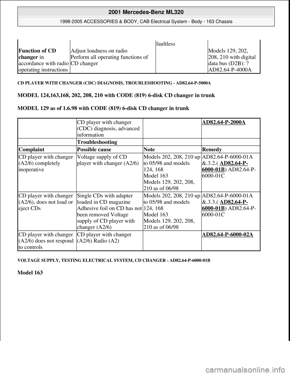
CD PLAYER WITH CHANGER (CDC) DIAGNOSIS, TROUBLESHOOTING - AD82.64-P-5000A
MODEL 124,163,168, 202, 208, 210 with CODE (819) 6-disk CD changer in trunk
MODEL 129 as of 1.6.98 with CODE (819) 6-disk CD changer in trunk
VOLTAGE SUPPLY, TESTING ELECTRICAL SYSTEM, CD CHANGER - AD82.64-P-6000-01B
Model 163
faultless
Function of CD
changer in
accordance with radio
operating instructionsAdjust loudness on radio
Perform all operating functions of
CD changer Models 129, 202,
208, 210 with digital
data bus (D2B): ?
AD82.64-P-4000A
CD player with changer
(CDC) diagnosis, advanced
information AD82.64-P-2000A
Troubleshooting
Complaint Possible cause Note Remedy
CD player with changer
(A2/6) completely
inoperativeVoltage supply of CD
player with changer (A2/6)Models 202, 208, 210 up
to 05/98 and models
124, 168
Model 163
Models 129, 202, 208,
210 as of 06/98AD82.64-P-6000-01A
&.3.2.( AD82.64
-P-
6000-01B) AD82.64-P-
6000-01C
CD player with changer
(A2/6), does not load or
eject CDsSingle CDs with adapter
loaded in CD magazine
Adhesive foil on CD has not
been removed Voltage
supply of CD player with
changer (A2/6)Models 202, 208, 210 up
to 05/98 and models
124, 168
Model 163
Models 129, 202, 208,
210 as of 06/98AD82.64-P-6000-01A
&.3.3.( AD82.64
-P-
6000-01B) AD82.64-P-
6000-01C
CD player with changer
(A2/6) does not respond
to controlsCD player with changer
(A2/6) Radio (A2) AD82.64-P-6000-02A
2001 Mercedes-Benz ML320
1998-2005 ACCESSORIES & BODY, CAB Electrical System - Body - 163 Chassis
me
Saturday, October 02, 2010 3:30:08 PMPage 247 © 2006 Mitchell Repair Information Company, LLC.
Page 2088 of 4133

16
Remove poly V-belt (8)
Installation:
Lock tensioning device with
a drift or pin (diameter 5 mm).
Model 163.154 /157 /172.
AR13.22-P-1202B
Model 163.174 /175.
AR13.22-P-1202BA
17
Detach the coolant line (16) at the cylinder
head on the left
6 mm socket hexagon
*WH58.30-Z-1001-06A
7 mm socket hexagon
*WH58.30-Z-1002-06A
18.1
Remove fender liner (9)
Only with engine 113.113.942 /965 / 981.
AR88.10-P-1300GH
19.1
Remove shield (10)
Only with engine 113.942 /965 /981.
20.1
Remove exhaust bracket (11)
Only with engine 113.942 /965 /981.
Support exhaust system.
21
Detach exhaust system at exhaust manifold
Installation:
On vehicles with engine
damage, the exhaust system must be
examined for swarfs before assembling and
any swarfs present must be removed, in order
to avoid consequential damage.
*BA14.10-P-1002-01B
22
Position crankshaft to 40° after ignition TDC
on cylinder 1
The engine must not be turned back;
otherwise the timing chain can get jammed.
AR05.10-P-6858V
Rotate engine at the crankshaft in running
direction until scribe mark 40° on pulley/
vibration damper corresponds with scribe
mark on timing case.
The grooves on the camshafts must be
pointing toward the inner V.
23
Lock camshafts with locating plates
Locating plate
*112589003200
Locating plate
*112589013200
24
Remove chain tensioner (17)
Model 163.154 /157 with engine 112.942/
970, model 163.172 with engine 113.942.
AR05.10-P-7800C
Model 163.174 /175 with engine 113.981/ 965.
AR05.10-P-7800CA
25.1
Remove oil filter housing (18) together with oil-
water heat exchanger
Engine 113.942.
AR18.20-P-3471B
Engine 112.942/970.
AR18.20-P-3471BA
26
Unscrew camshaft sprockets (19)
If camshaft sprockets are removed,
engine must no longer be cranked, otherwise
timing chain might jam.
Engine 113.942 /965 /981:
#
Tie timing chain tight on both camshaft
sprockets with tie straps.
Engine 112.942 /970:
#
Right-hand camshaft sprocket:
Tie timing chain tight on camshaft sprocket
with tie strap.
Left-hand camshaft sprocket:
Mark camshaft sprocket to timing chain and
remove camshaft sprocket.
It is not possible for the timing chain to
jump across at the crankshaft and balancing
shaft.
After installation:
#
Inspect basic position of camshafts.
AR05.10-P-6858V
If necessary after checking:
#
Set the basic position of camshafts
AR05.20-P-6020AU
Open-end wrench
*112589000100
Insertion tool
*112589010300
Torque wrench
*001589722100
*BA05.20-P-1001-01B
27
Remove camshaft bearing bridges (28)
Pay attention to slackening and tightening
pattern!
AR05.20-P-7103AU
28
Unscrew bolts, cylinder head
!
timing case
cover (20)
*BA01.40-P-1002-01C
Copyright DaimlerChrysler AG 20.05.2006 CD-Ausgabe G/10/04 . This WIS print-out will not be recorde
d by Modification services.
Page 4
Page 2096 of 4133

16
Remove poly V-belt (8)
Installation:
Lock tensioning device with
a drift or pin (diameter 5 mm).
Model 163.154 /157 /172.
AR13.22-P-1202B
Model 163.174 /175.
AR13.22-P-1202BA
17
Detach the coolant line (16) at the cylinder
head on the left
6 mm socket hexagon
*WH58.30-Z-1001-06A
7 mm socket hexagon
*WH58.30-Z-1002-06A
18.1
Remove fender liner (9)
Only with engine 113.113.942 /965 / 981.
AR88.10-P-1300GH
19.1
Remove shield (10)
Only with engine 113.942 /965 /981.
20.1
Remove exhaust bracket (11)
Only with engine 113.942 /965 /981.
Support exhaust system.
21
Detach exhaust system at exhaust manifold
Installation:
On vehicles with engine
damage, the exhaust system must be
examined for swarfs before assembling and
any swarfs present must be removed, in order
to avoid consequential damage.
*BA14.10-P-1002-01B
22
Position crankshaft to 40° after ignition TDC
on cylinder 1
The engine must not be turned back;
otherwise the timing chain can get jammed.
AR05.10-P-6858V
Rotate engine at the crankshaft in running
direction until scribe mark 40° on pulley/
vibration damper corresponds with scribe
mark on timing case.
The grooves on the camshafts must be
pointing toward the inner V.
23
Lock camshafts with locating plates
Locating plate
*112589003200
Locating plate
*112589013200
24
Remove chain tensioner (17)
Model 163.154 /157 with engine 112.942/
970, model 163.172 with engine 113.942.
AR05.10-P-7800C
Model 163.174 /175 with engine 113.981/ 965.
AR05.10-P-7800CA
25.1
Remove oil filter housing (18) together with oil-
water heat exchanger
Engine 113.942.
AR18.20-P-3471B
Engine 112.942/970.
AR18.20-P-3471BA
26
Unscrew camshaft sprockets (19)
If camshaft sprockets are removed,
engine must no longer be cranked, otherwise
timing chain might jam.
Engine 113.942 /965 /981:
#
Tie timing chain tight on both camshaft
sprockets with tie straps.
Engine 112.942 /970:
#
Right-hand camshaft sprocket:
Tie timing chain tight on camshaft sprocket
with tie strap.
Left-hand camshaft sprocket:
Mark camshaft sprocket to timing chain and
remove camshaft sprocket.
It is not possible for the timing chain to
jump across at the crankshaft and balancing
shaft.
After installation:
#
Inspect basic position of camshafts.
AR05.10-P-6858V
If necessary after checking:
#
Set the basic position of camshafts
AR05.20-P-6020AU
Open-end wrench
*112589000100
Insertion tool
*112589010300
Torque wrench
*001589722100
*BA05.20-P-1001-01B
27
Remove camshaft bearing bridges (28)
Pay attention to slackening and tightening
pattern!
AR05.20-P-7103AU
28
Unscrew bolts, cylinder head
!
timing case
cover (20)
*BA01.40-P-1002-01C
Copyright DaimlerChrysler AG 20.05.2006 CD-Ausgabe G/10/04 . This WIS print-out will not be recorde
d by Modification services.
Page 4
Page 2232 of 4133

AP18.00-P-0101AR
Engine - oil and filter change
20.1.99
ENGINE
612
Modification notes
12.9.02
Engine oil level modified
Step 9:
Only Model 203:
Up to engine end number: 134 163 oil level
MAX. 135
mm,
MIN 110
mm.
As of engine end number: 134 164 oil level
MAX. 124,5
mm,
MIN 99,5
mm.
Remove
Danger!
Risk of death
cased by vehicle slipping or
toppling off of the lifting platform.
Align vehicle between the columns of the
hydraulic hoist and position the four support
plates below the hoist support points specified
by the vehicle manufacturer.
AS00.00-Z-0010-01A
Danger!
Risk of accident
caused by vehicle starting
off by itself when engine is running.
Risk of
injury
caused by contusions and burns when
working in engine during starting procedure
Secure vehicle to prevent it from moving.
Wear closed and snug-fitting work clothes.
Do not grasp hot or rotating parts.
AS00.00-Z-0005-01A
Change the engine oil only when the engine
is at operating temperature
1
Remove trim panel of cylinder head cover
AR01.20-P-5014-02B
2
Replace oil filter element, drain oil filter
Model 203: Remove clamp attaching fuel
line in order to insert wrench socket.
AP18.00-P-0101-06EG
*BA18.20-P-1002-01G
Socket wrench bit
*103589020900
3.1
Suction off engine oil
AP18.00-P-0101-02Z
4.1
Remove rear left frame cross brace
Only necessary when draining engine oil
at oil drain plug.
MODEL 163
f
Model 203 except 203.018/218/718, 209
AR94.30-P-5300P
Model 210
AR94.30-P-5300AB
4.2
Detach lower engine compartment paneling
Only necessary when draining engine oil
at oil drain plug.
f
Only Model 203.018/218/718
AR61.20-P-1105P
5.1
Unscrew oil drain plug, drain engine oil
Install
6.1
Screw in oil drain plug
Replace sealing ring, in order to avoid
leakage.
*BA01.45-P-1003-01A
7
Pour in engine oil
Note specified and approved quality
grades and viscosity classes conforming to
SAE at enduring ambient temperatures.
*BE18.00-P-1001-02B
*BF18.00-P-1001-01A
g
Viscosity classes of engine oils (car engines)
Sheet 224.1
BB00.40-P-0224-01A
8
Run engine and inspect for leaks
9
Switch off engine
10.1
Fit on bottom part of noise encapsulation
Only necessary when draining engine oil
at oil drain plug.
f
Model 210
AR94.30-P-5300AB
MODEL 203, 209
AR94.30-P-5300P
MODEL 163
10.2
Install lower engine compartment paneling.
Only necessary when draining engine oil
at oil drain plug.
f
Only Model 203.018/218/718
AR61.20-P-1105P
Copyright DaimlerChrysler AG 20.05.2006 CD-Ausgabe G/10/04 . This WIS print-out will not be recorde
d by Modification services.
Page 1
Page 2234 of 4133
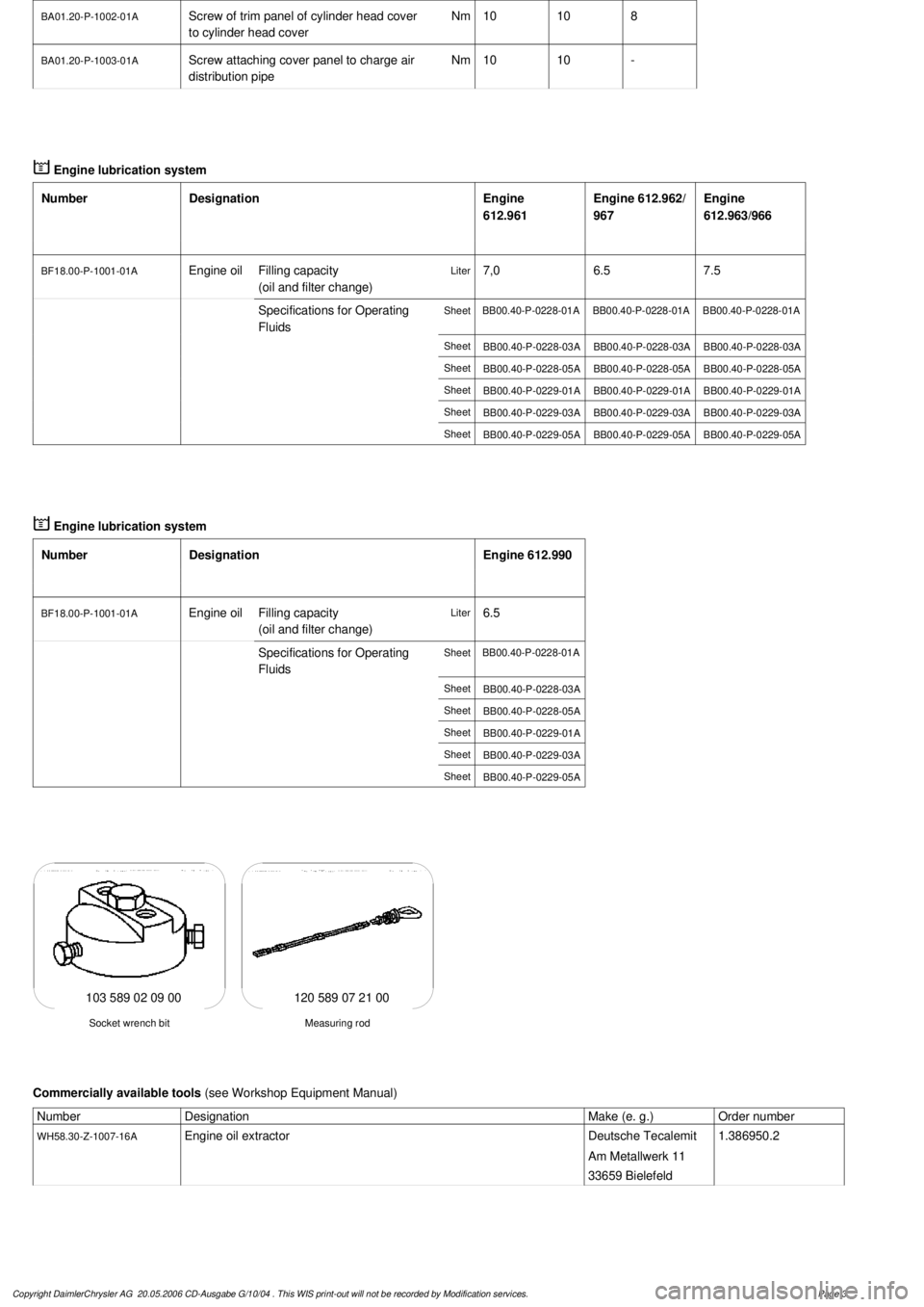
BA01.20-P-1002-01A
Screw of trim panel of cylinder head cover
to cylinder head cover
Nm
1010
8
BA01.20-P-1003-01A
Screw attaching cover panel to charge air
distribution pipe
Nm
1010
-
Designation
Engine
612.961
Engine 612.962/
967
Engine
612.963/966
BF18.00-P-1001-01A
Engine oil
Filling capacity
(oil and filter change)
Liter
7,06.57.5
Specifications for Operating
Fluids
SheetBB00.40-P-0228-01ABB00.40-P-0228-01ABB00.40-P-0228-01A
SheetBB00.40-P-0228-03ABB00.40-P-0228-03ABB00.40-P-0228-03A
SheetBB00.40-P-0228-05ABB00.40-P-0228-05ABB00.40-P-0228-05A
SheetBB00.40-P-0229-01ABB00.40-P-0229-01ABB00.40-P-0229-01A
SheetBB00.40-P-0229-03ABB00.40-P-0229-03ABB00.40-P-0229-03A
SheetBB00.40-P-0229-05ABB00.40-P-0229-05ABB00.40-P-0229-05A
Engine lubrication system
Number
Designation
Engine 612.990
BF18.00-P-1001-01A
Engine oil
Filling capacity
(oil and filter change)
Liter
6.5
Specifications for Operating
Fluids
SheetBB00.40-P-0228-01A
SheetBB00.40-P-0228-03A
SheetBB00.40-P-0228-05A
SheetBB00.40-P-0229-01A
SheetBB00.40-P-0229-03A
SheetBB00.40-P-0229-05A
120 589 07 21 00
Measuring rod
Socket wrench bit
103 589 02 09 00
Commercially available tools
(see Workshop Equipment Manual)
Number
Designation
Make (e. g.)
Order number
WH58.30-Z-1007-16A
Engine oil extractor
Deutsche Tecalemit
Am Metallwerk 11
33659 Bielefeld
1.386950.2
Copyright DaimlerChrysler AG 20.05.2006 CD-Ausgabe G/10/04 . This WIS print-out will not be recorde
d by Modification services.
Page 3