1997 MERCEDES-BENZ ML350 stop start
[x] Cancel search: stop startPage 1557 of 4133
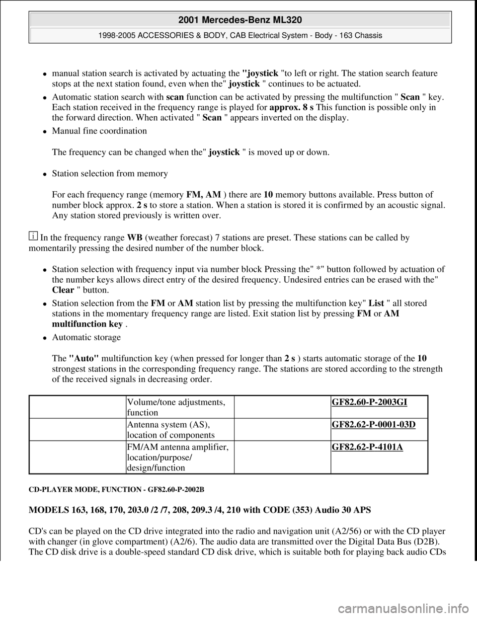
manual station search is activated by actuating the "joystick "to left or right. The station search feature
stops at the next station found, even when the" joystick " continues to be actuated.
Automatic station search with scan function can be activated by pressing the multifunction " Scan " key.
Each station received in the frequency range is played for approx. 8 s This function is possible only in
the forward direction. When activated " Scan " appears inverted on the display.
Manual fine coordination
The frequency can be changed when the" joystick " is moved up or down.
Station selection from memory
For each frequency range (memory FM, AM ) there are 10 memory buttons available. Press button of
number block approx. 2 s to store a station. When a station is stored it is confirmed by an acoustic signal.
Any station stored previously is written over.
In the frequency range WB (weather forecast) 7 stations are preset. These stations can be called by
momentarily pressing the desired number of the number block.
Station selection with frequency input via number block Pressing the" *" button followed by actuation of
the number keys allows direct entry of the desired frequency. Undesired entries can be erased with the"
Clear " button.
Station selection from the FM or AM station list by pressing the multifunction key" List " all stored
stations in the momentary frequency range are listed. Exit station list by pressing FM or AM
multifunction key .
Automatic storage
The "Auto" multifunction key (when pressed for longer than 2 s ) starts automatic storage of the 10
strongest stations in the corresponding frequency range. The stations are stored according to the strength
of the received signals in decreasing order.
CD-PLAYER MODE, FUNCTION - GF82.60-P-2002B
MODELS 163, 168, 170, 203.0 /2 /7, 208, 209.3 /4, 210 with CODE (353) Audio 30 APS
CD's can be played on the CD drive integrated into the radio and navigation unit (A2/56) or with the CD player
with changer (in glove compartment) (A2/6). The audio data are transmitted over the Digital Data Bus (D2B).
The CD disk drive is a double-speed standard CD disk drive, which is suitable both for pla
ying back audio CDs
Volume/tone adjustments,
function GF82.60-P-2003GI
Antenna system (AS),
location of components GF82.62-P-0001-03D
FM/AM antenna amplifier,
location/purpose/
design/function GF82.62-P-4101A
2001 Mercedes-Benz ML320
1998-2005 ACCESSORIES & BODY, CAB Electrical System - Body - 163 Chassis
me
Saturday, October 02, 2010 3:30:05 PMPage 62 © 2006 Mitchell Repair Information Company, LLC.
Page 1636 of 4133
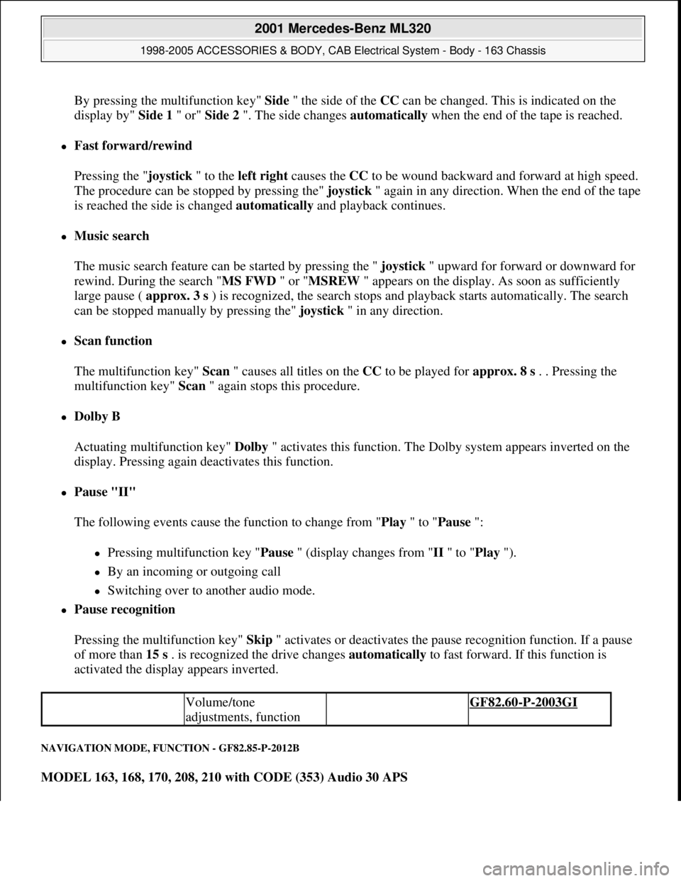
By pressing the multifunction key" Side" the side of the CCcan be changed. This is indicated on the
display by" Side 1 " or" Side 2 ". The side changes automatically when the end of the tape is reached.
Fast forward/rewind
Pressing the "joystick " to the left right causes the CC to be wound backward and forward at high speed.
The procedure can be stopped by pressing the" joystick" again in any direction. When the end of the tape
is reached the side is changed automatically and playback continues.
Music search
The music search feature can be started by pressing the " joystick " upward for forward or downward for
rewind. During the search "MS FWD " or "MSREW " appears on the display. As soon as sufficiently
large pause ( approx. 3 s ) is recognized, the search stops and playback starts automatically. The search
can be stopped manually by pressing the" joystick " in any direction.
Scan function
The multifunction key" Scan " causes all titles on the CC to be played for approx. 8 s . . Pressing the
multifunction key" Scan " again stops this procedure.
Dolby B
Actuating multifunction key" Dolby " activates this function. The Dolby system appears inverted on the
display. Pressing again deactivates this function.
Pause "II"
The following events cause the function to change from "Play " to "Pause ":
Pressing multifunction key "Pause " (display changes from "II " to "Play ").
By an incoming or outgoing call
Switching over to another audio mode.
Pause recognition
Pressing the multifunction key" Skip " activates or deactivates the pause recognition function. If a pause
of more than 15 s . is recognized the drive changes automatically to fast forward. If this function is
activated the display appears inverted.
NAVIGATION MODE, FUNCTION - GF82.85-P-2012B
MODEL 163, 168, 170, 208, 210 with CODE (353) Audio 30 APS
Volume/tone
adjustments, function GF82.60-P-2003GI
2001 Mercedes-Benz ML320
1998-2005 ACCESSORIES & BODY, CAB Electrical System - Body - 163 Chassis
me
Saturday, October 02, 2010 3:30:06 PMPage 141 © 2006 Mitchell Repair Information Company, LLC.
Page 1644 of 4133
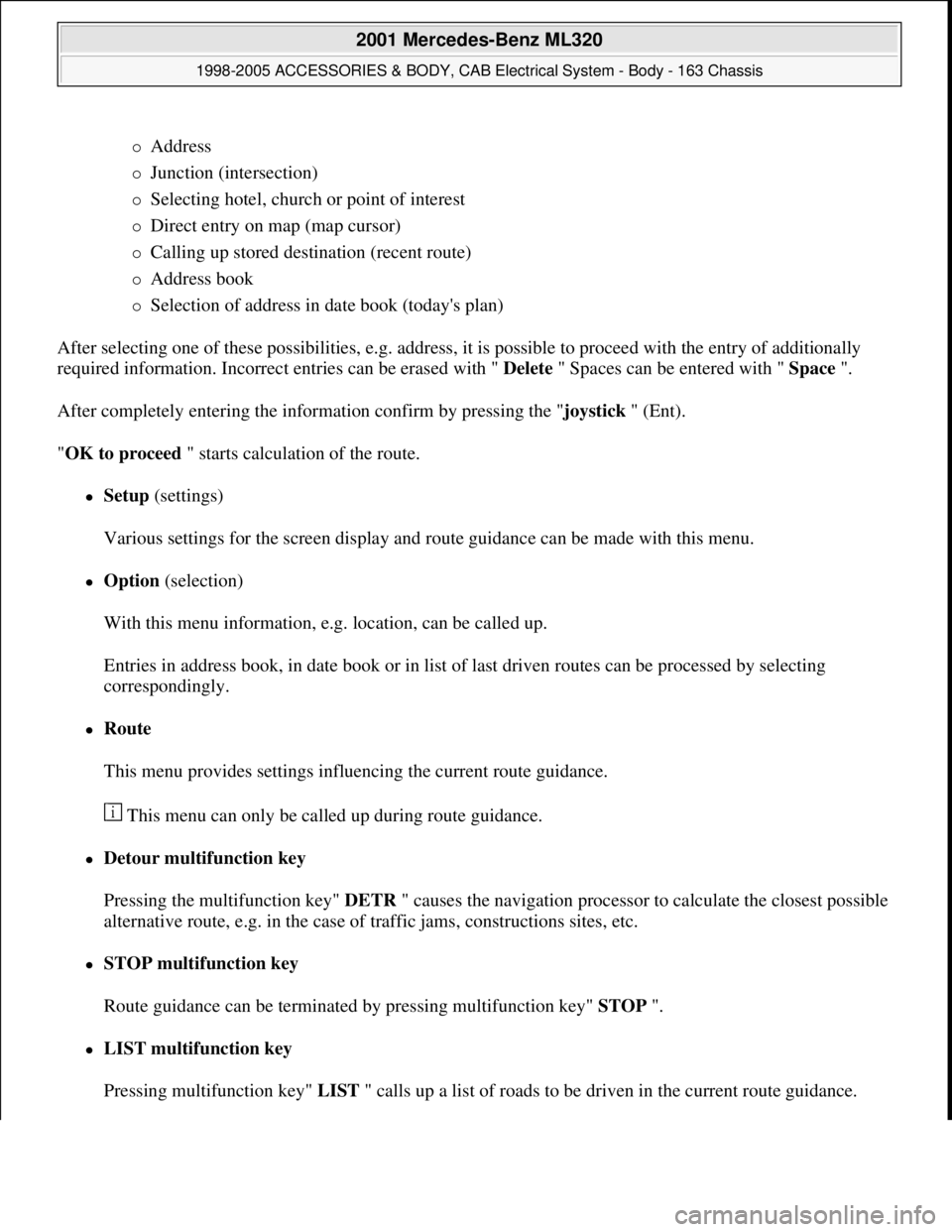
Address
Junction (intersection)
Selecting hotel, church or point of interest
Direct entry on map (map cursor)
Calling up stored destination (recent route)
Address book
Selection of address in date book (today's plan)
After selecting one of these possibilities, e.g. address, it is possible to proceed with the entry of additionally
required information. Incorrect entries can be erased with " Delete " Spaces can be entered with " Space ".
After completely entering the information confirm by pressing the "joystick " (Ent).
"OK to proceed " starts calculation of the route.
Setup (settings)
Various settings for the screen display and route guidance can be made with this menu.
Option (selection)
With this menu information, e.g. location, can be called up.
Entries in address book, in date book or in list of last driven routes can be processed by selecting
correspondingly.
Route
This menu provides settings influencing the current route guidance.
This menu can only be called up during route guidance.
Detour multifunction key
Pressing the multifunction key" DETR " causes the navigation processor to calculate the closest possible
alternative route, e.g. in the case of traffic jams, constructions sites, etc.
STOP multifunction key
Route guidance can be terminated by pressing multifunction key" STOP ".
LIST multifunction key
Pressin
g multifunction key" LIST " calls up a list of roads to be driven in the current route guidance.
2001 Mercedes-Benz ML320
1998-2005 ACCESSORIES & BODY, CAB Electrical System - Body - 163 Chassis
me
Saturday, October 02, 2010 3:30:06 PMPage 149 © 2006 Mitchell Repair Information Company, LLC.
Page 2042 of 4133
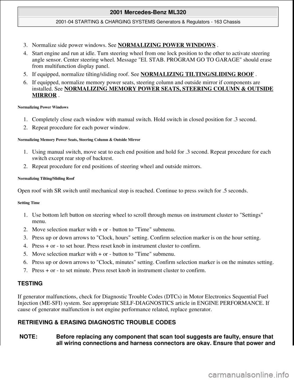
3. Normalize side power windows. See NORMALIZING POWER WINDOWS .
4. Start engine and run at idle. Turn steering wheel from one lock position to the other to activate steering
angle sensor. Center steering wheel. Message "EI. STAB. PROGRAM GO TO GARAGE" should erase
from multifunction display panel.
5. If equipped, normalize tilting/sliding roof. See NORMALIZING TILTING/SLIDING ROOF
.
6. If equipped, normalize memory power seats, steering column and outside mirror if components are
installed. See NORMALIZING MEMORY POWER SEATS, STEERING COLUMN & OUTSIDE
MIRROR .
Normalizing Power Windows
1. Completely close each window with manual switch. Hold switch in closed position for .3 second.
2. Repeat procedure for each power window.
Normalizing Memory Power Seats, Steering Column & Outside Mirror
1. Using manual switch, move seat to each end position and hold for .3 second. Repeat procedure for each
switch except rear stop of backrest.
2. Repeat procedure for end positions of steering wheel and outside mirrors.
Normalizing Tilting/Sliding Roof
Open roof with SR switch until mechanical stop is reached. Continue to press switch for .5 seconds.
Setting Time
1. Use bottom left button on steering wheel to scroll through menus on instrument cluster to "Settings"
menu.
2. Move selection marker with + or - button to "Time" submenu.
3. Press up or down arrows to "Clock, hours" setting. Confirm selection marker is on the hour setting.
4. Press + or - to set hour. Press reset knob in instrument cluster to confirm.
5. Move selection marker with + or - button to "Time" submenu.
6. Press up or down arrows to "Clock, minutes" setting. Confirm selection marker is on the minutes setting.
7. Press + or - to set minute. Press reset knob in instrument cluster to confirm.
TESTING
If generator malfunctions, check for Diagnostic Trouble Codes (DTCs) in Motor Electronics Sequential Fuel
Injection (ME-SFI) system. See appropriate SELF-DIAGNOSTICS article in ENGINE PERFORMANCE. If
cause of generator malfunction is not engine performance related, replace generator.
RETRIEVING & ERASING DIAGNOSTIC TROUBLE CODES
NOTE: Before replacing any component that scan tool suggests are faulty, ensure that
all wiring connections and harness connectors are okay. Ensure that power and
2001 Mercedes-Benz ML320
2001-04 STARTING & CHARGING SYSTEMS Generators & Regulators - 163 Chassis
me
Saturday, October 02, 2010 3:20:32 PMPage 8 © 2006 Mitchell Repair Information Company, LLC.
Page 2149 of 4133
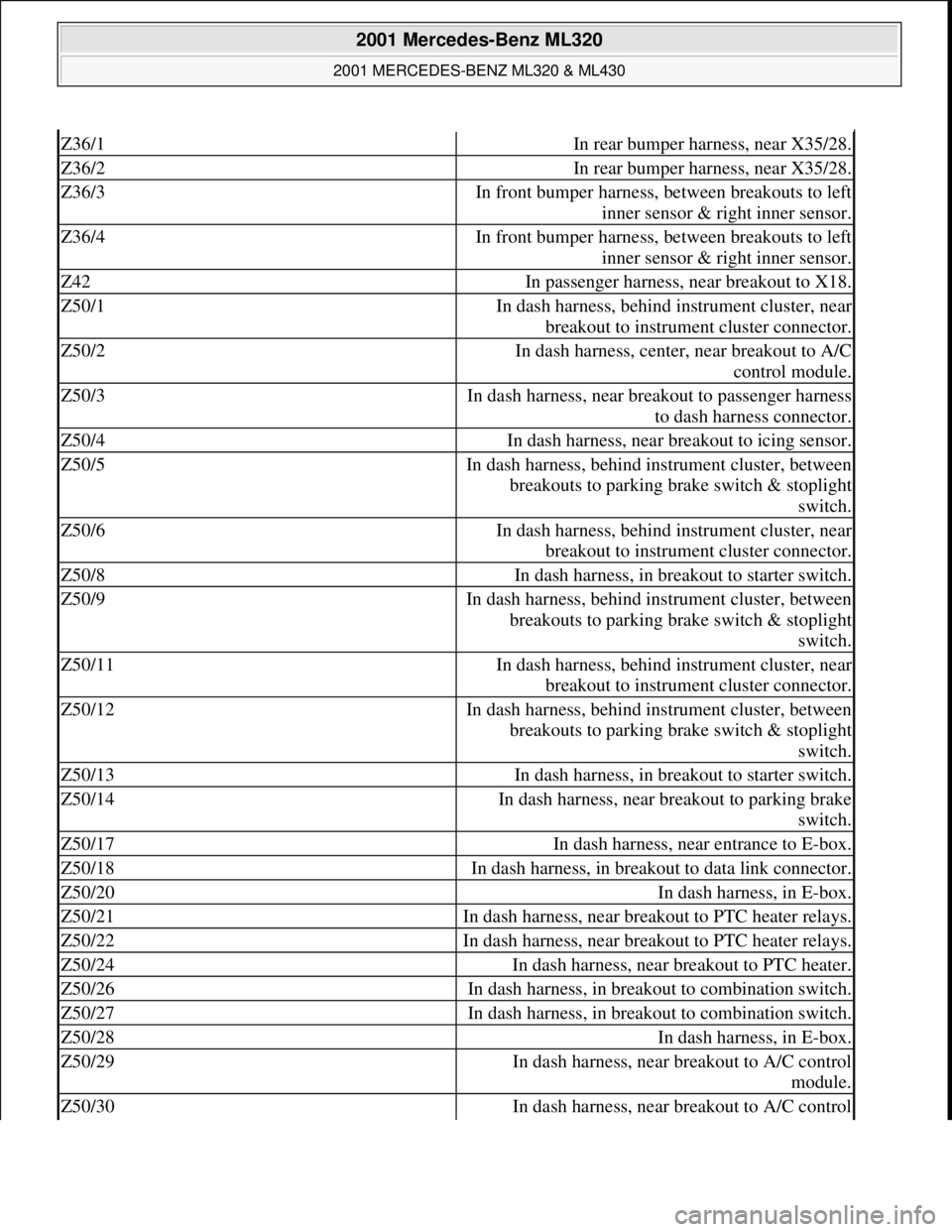
Z36/1In rear bumper harness, near X35/28.
Z36/2In rear bumper harness, near X35/28.
Z36/3In front bumper harness, between breakouts to left
inner sensor & right inner sensor.
Z36/4In front bumper harness, between breakouts to left
inner sensor & right inner sensor.
Z42In passenger harness, near breakout to X18.
Z50/1In dash harness, behind instrument cluster, near
breakout to instrument cluster connector.
Z50/2In dash harness, center, near breakout to A/C
control module.
Z50/3In dash harness, near breakout to passenger harness
to dash harness connector.
Z50/4In dash harness, near breakout to icing sensor.
Z50/5In dash harness, behind instrument cluster, between
breakouts to parking brake switch & stoplight
switch.
Z50/6In dash harness, behind instrument cluster, near
breakout to instrument cluster connector.
Z50/8In dash harness, in breakout to starter switch.
Z50/9In dash harness, behind instrument cluster, between
breakouts to parking brake switch & stoplight
switch.
Z50/11In dash harness, behind instrument cluster, near
breakout to instrument cluster connector.
Z50/12In dash harness, behind instrument cluster, between
breakouts to parking brake switch & stoplight
switch.
Z50/13In dash harness, in breakout to starter switch.
Z50/14In dash harness, near breakout to parking brake
switch.
Z50/17In dash harness, near entrance to E-box.
Z50/18In dash harness, in breakout to data link connector.
Z50/20In dash harness, in E-box.
Z50/21In dash harness, near breakout to PTC heater relays.
Z50/22In dash harness, near breakout to PTC heater relays.
Z50/24In dash harness, near breakout to PTC heater.
Z50/26In dash harness, in breakout to combination switch.
Z50/27In dash harness, in breakout to combination switch.
Z50/28In dash harness, in E-box.
Z50/29In dash harness, near breakout to A/C control
module.
Z50/30In dash harness, near breakout to A/C control
2001 Mercedes-Benz ML320
2001 MERCEDES-BENZ ML320 & ML430
me
Saturday, October 02, 2010 3:21:17 PMPage 9 © 2006 Mitchell Repair Information Company, LLC.
Page 2390 of 4133
covers and sealing ring of the hot
film air mass sensor in the air
filter housing with lubricant.
Models 230.474, 203.065/265,
170.466AR09.10-P-1150SVK
Lubricant
*BR00.45
-Z-1002-
06A
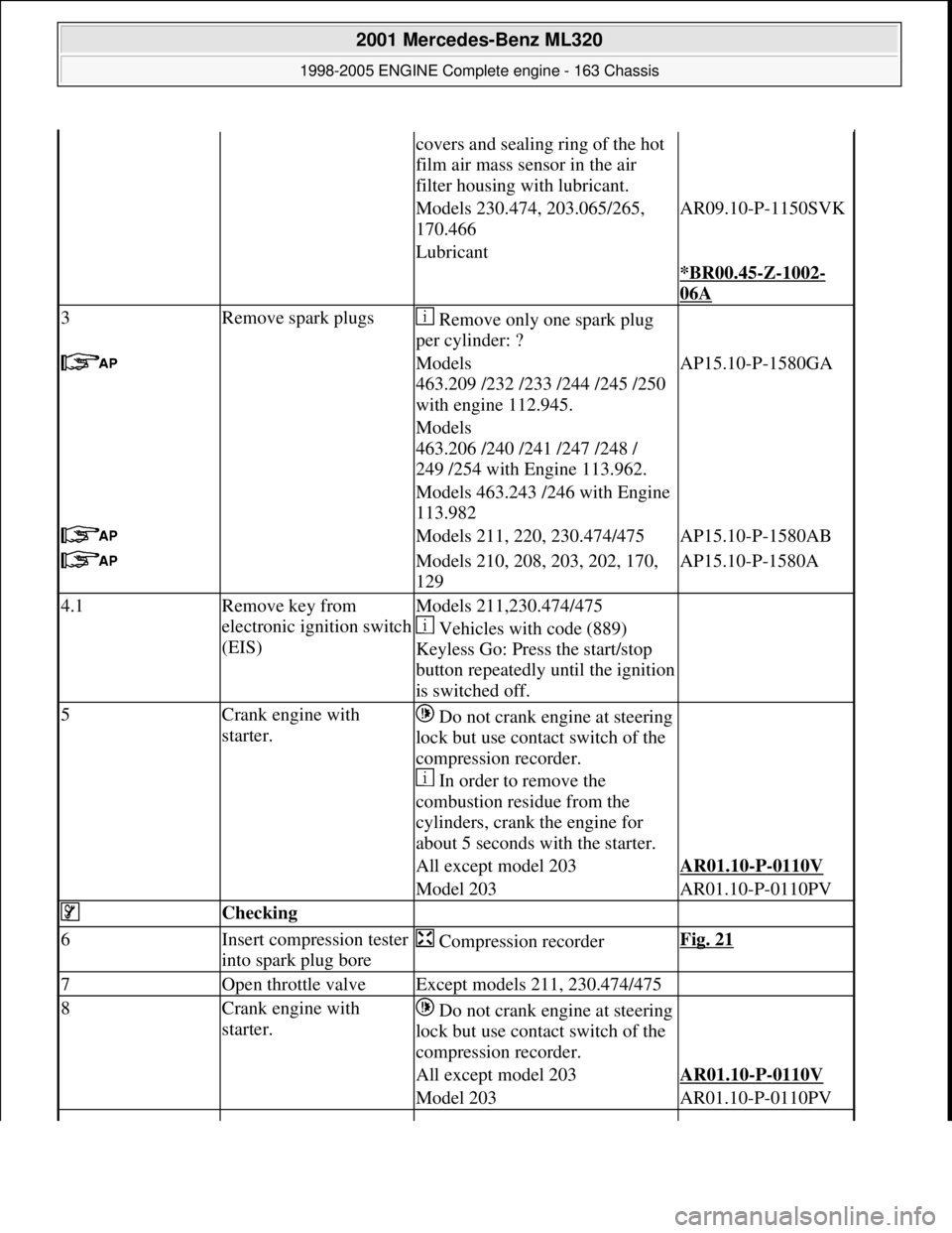
3Remove spark plugs Remove only one spark plug
per cylinder: ?
Models
463.209 /232 /233 /244 /245 /250
with engine 112.945.AP15.10-P-1580GA
Models
463.206 /240 /241 /247 /248 /
249 /254 with Engine 113.962.
Models 463.243 /246 with Engine
113.982
Models 211, 220, 230.474/475AP15.10-P-1580AB
Models 210, 208, 203, 202, 170,
129AP15.10-P-1580A
4.1Remove key from
electronic ignition switch
(EIS)Models 211,230.474/475
Vehicles with code (889)
Keyless Go: Press the start/stop
button repeatedly until the ignition
is switched off.
5Crank engine with
starter. Do not crank engine at steering
lock but use contact switch of the
compression recorder.
In order to remove the
combustion residue from the
cylinders, crank the engine for
about 5 seconds with the starter.
All except model 203AR01.10-P-0110V
Model 203AR01.10-P-0110PV
Checking
6Insert compression tester
into spark plug bore Compression recorderFig. 21
7Open throttle valveExcept models 211, 230.474/475
8Crank engine with
starter. Do not crank engine at steering
lock but use contact switch of the
compression recorder.
All except model 203AR01.10-P-0110V
Model 203AR01.10-P-0110PV
2001 Mercedes-Benz ML320
1998-2005 ENGINE Complete engine - 163 Chassis
me
Saturday, October 02, 2010 3:17:56 PMPage 34 © 2006 Mitchell Repair Information Company, LLC.
Page 2403 of 4133
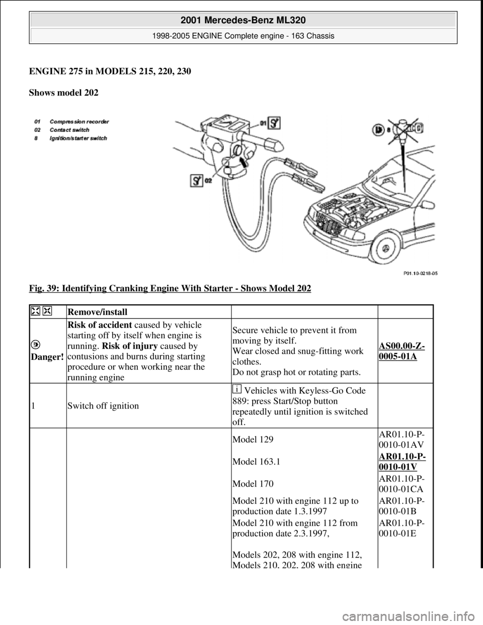
ENGINE 275 in MODELS 215, 220, 230
Shows model 202
Fig. 39: Identifying Cranking Engine With Starter
- Shows Model 202
Remove/install
Danger!
Risk of accident caused by vehicle
starting off by itself when engine is
running. Risk of injury caused by
contusions and burns during starting
procedure or when working near the
running engineSecure vehicle to prevent it from
moving by itself.
Wear closed and snug-fitting work
clothes.
Do not grasp hot or rotating parts.
AS00.00-Z-
0005-01A
1Switch off ignition
Vehicles with Keyless-Go Code
889: press Start/Stop button
repeatedly until ignition is switched
off.
Model 129AR01.10-P-
0010-01AV
Model 163.1AR01.10-P-
0010-01V
Model 170AR01.10-P-
0010-01CA
Model 210 with engine 112 up to
production date 1.3.1997AR01.10-P-
0010-01B
Model 210 with engine 112 from
production date 2.3.1997,AR01.10-P-
0010-01E
Models 202, 208 with engine 112,
Models 210, 202, 208 with engine
2001 Mercedes-Benz ML320
1998-2005 ENGINE Complete engine - 163 Chassis
me
Saturday, October 02, 2010 3:17:56 PMPage 47 © 2006 Mitchell Repair Information Company, LLC.
Page 2404 of 4133
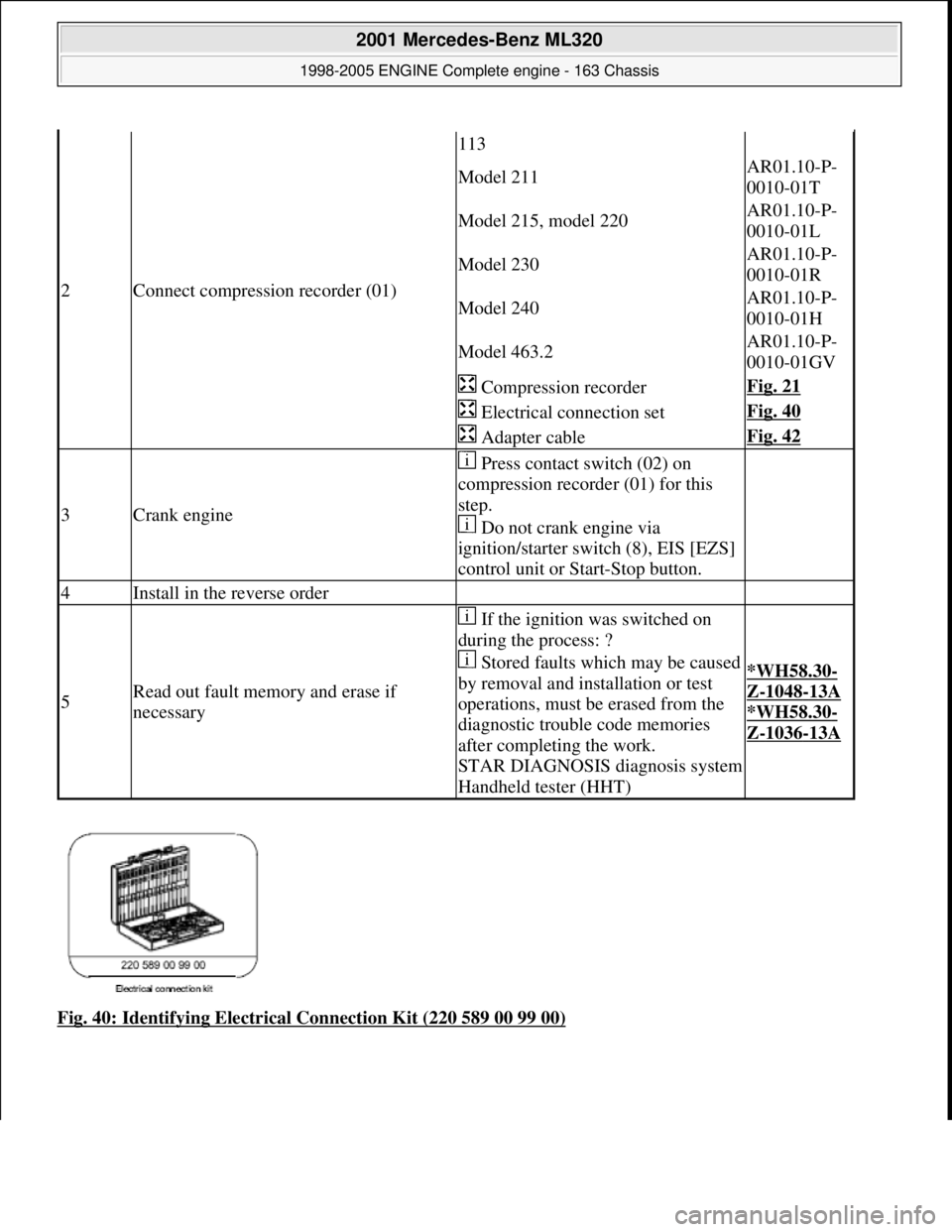
Fig. 40: Identifying Electrical Connection Kit (220 589 00 99 00)
2Connect compression recorder (01)
113
Model 211AR01.10-P-
0010-01T
Model 215, model 220AR01.10-P-
0010-01L
Model 230AR01.10-P-
0010-01R
Model 240AR01.10-P-
0010-01H
Model 463.2AR01.10-P-
0010-01GV
Compression recorderFig. 21
Electrical connection setFig. 40
Adapter cableFig. 42
3Crank engine
Press contact switch (02) on
compression recorder (01) for this
step.
Do not crank engine via
ignition/starter switch (8), EIS [EZS]
control unit or Start-Stop button.
4Install in the reverse order
5Read out fault memory and erase if
necessary
If the ignition was switched on
during the process: ?
Stored faults which may be caused
by removal and installation or test
operations, must be erased from the
diagnostic trouble code memories
after completing the work.
STAR DIAGNOSIS di agnosis system
Handheld tester (HHT)
*WH58.30-
Z-1048-13A
*WH58.30-
Z-1036-13A
2001 Mercedes-Benz ML320
1998-2005 ENGINE Complete engine - 163 Chassis
me
Saturday, October 02, 2010 3:17:56 PMPage 48 © 2006 Mitchell Repair Information Company, LLC.