1997 MERCEDES-BENZ ML350 stop start
[x] Cancel search: stop startPage 3628 of 4133
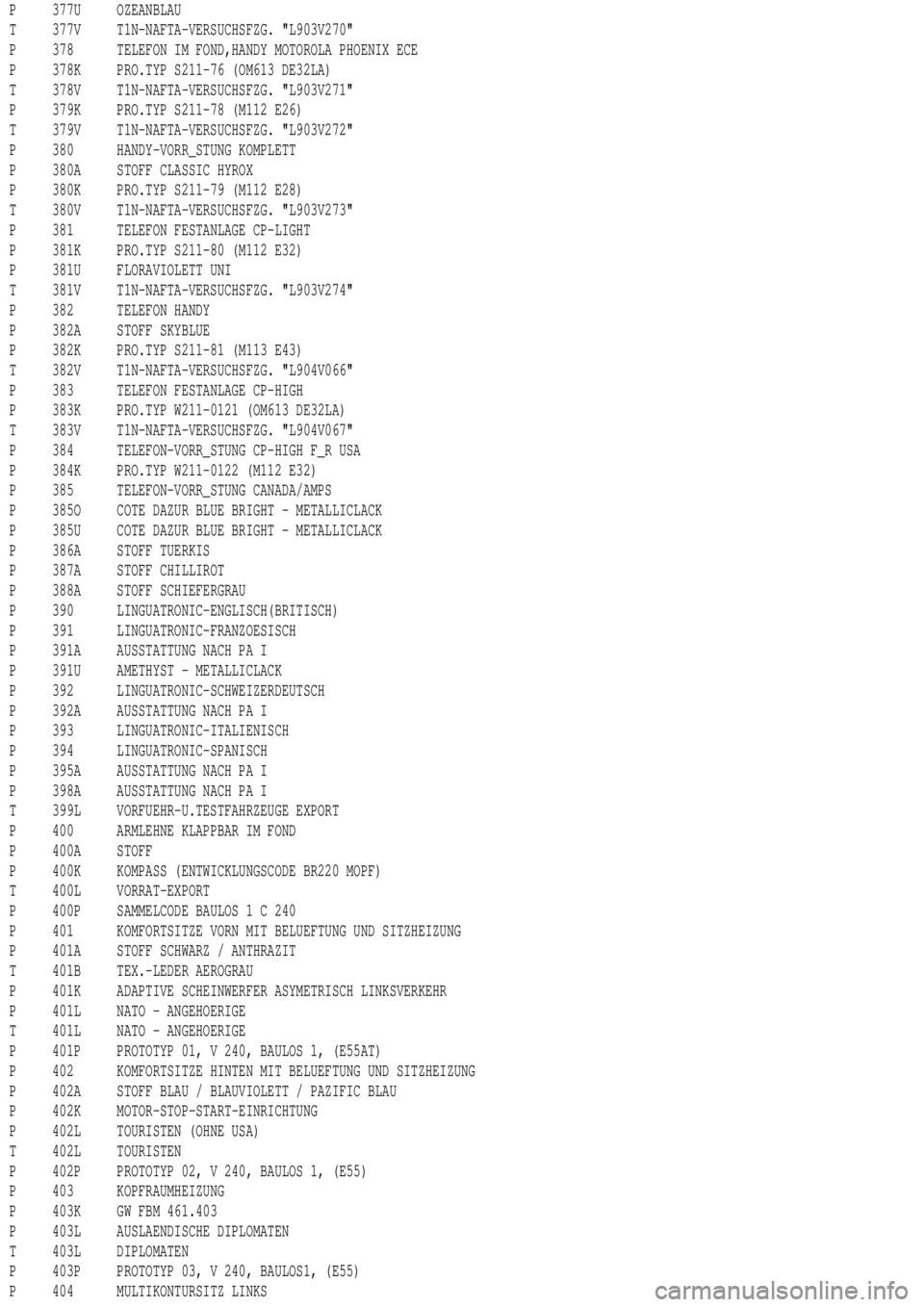
P 377U OZEANBLAU
T 377V T1N-NAFTA-VERSUCHSFZG. "L903V270"
P 378 TELEFON IM FOND,HANDY MOTOROLA PHOENIX ECE
P 378K PRO.TYP S211-76 (OM613 DE32LA)
T 378V T1N-NAFTA-VERSUCHSFZG. "L903V271"
P 379K PRO.TYP S211-78 (M112 E26)
T 379V T1N-NAFTA-VERSUCHSFZG. "L903V272"
P 380 HANDY-VORR_STUNG KOMPLETT
P 380A STOFF CLASSIC HYROX
P 380K PRO.TYP S211-79 (M112 E28)
T 380V T1N-NAFTA-VERSUCHSFZG. "L903V273"
P 381 TELEFON FESTANLAGE CP-LIGHT
P 381K PRO.TYP S211-80 (M112 E32)
P 381U FLORAVIOLETT UNI
T 381V T1N-NAFTA-VERSUCHSFZG. "L903V274"
P 382 TELEFON HANDY
P 382A STOFF SKYBLUE
P 382K PRO.TYP S211-81 (M113 E43)
T 382V T1N-NAFTA-VERSUCHSFZG. "L904V066"
P 383 TELEFON FESTANLAGE CP-HIGH
P 383K PRO.TYP W211-0121 (OM613 DE32LA)
T 383V T1N-NAFTA-VERSUCHSFZG. "L904V067"
P 384 TELEFON-VORR_STUNG CP-HIGH F_R USA
P 384K PRO.TYP W211-0122 (M112 E32)
P 385 TELEFON-VORR_STUNG CANADA/AMPS
P 385O COTE DAZUR BLUE BRIGHT - METALLICLACK
P 385U COTE DAZUR BLUE BRIGHT - METALLICLACK
P 386A STOFF TUERKIS
P 387A STOFF CHILLIROT
P 388A STOFF SCHIEFERGRAU
P 390 LINGUATRONIC-ENGLISCH(BRITISCH)
P 391 LINGUATRONIC-FRANZOESISCH
P 391A AUSSTATTUNG NACH PA I
P 391U AMETHYST - METALLICLACK
P 392 LINGUATRONIC-SCHWEIZERDEUTSCH
P 392A AUSSTATTUNG NACH PA I
P 393 LINGUATRONIC-ITALIENISCH
P 394 LINGUATRONIC-SPANISCH
P 395A AUSSTATTUNG NACH PA I
P 398A AUSSTATTUNG NACH PA I
T 399L VORFUEHR-U.TESTFAHRZEUGE EXPORT
P 400 ARMLEHNE KLAPPBAR IM FOND
P 400A STOFF
P 400K KOMPASS (ENTWICKLUNGSCODE BR220 MOPF)
T 400L VORRAT-EXPORT
P 400P SAMMELCODE BAULOS1C240
P 401 KOMFORTSITZE VORN MIT BELUEFTUNG UND SITZHEIZUNG
P 401A STOFF SCHWARZ / ANTHRAZIT
T 401B TEX.-LEDER AEROGRAU
P 401K ADAPTIVE SCHEINWERFER ASYMETRISCH LINKSVERKEHR
P 401L NATO - ANGEHOERIGE
T 401L NATO - ANGEHOERIGE
P 401P PROTOTYP 01, V 240, BAULOS 1, (E55AT)
P 402 KOMFORTSITZE HINTEN MIT BELUEFTUNG UND SITZHEIZUNG
P 402A STOFF BLAU / BLAUVIOLETT / PAZIFIC BLAU
P 402K MOTOR-STOP-START-EINRICHTUNG
P 402L TOURISTEN (OHNE USA)
T 402L TOURISTEN
P 402P PROTOTYP 02, V 240, BAULOS 1, (E55)
P 403 KOPFRAUMHEIZUNG
P 403K GW FBM 461.403
P 403L AUSLAENDISCHE DIPLOMATEN
T 403L DIPLOMATEN
P 403P PROTOTYP 03, V 240, BAULOS1, (E55)
P 404 MULTIKONTURSITZ LINKS
Page 3683 of 4133
P M58 HUBRAUM 5,8 LITER
P M60 HUBRAUM 6,0 LITER
P M602 R5-DIESELMOTOR OM602
P M603 R6-DIESELMOTOR OM603
P M605 R5-DIESELMOTOR OM605
P M606 R6-DIESELMOTOR OM606
P M611 R4-DIESELMOTOR OM611
P M612 R5-DIESELMOTOR OM612
P M613 R6-DIESELMOTOR M613
P M628 V8-DIESELMOTOR M628
P M63 HUBRAUM 6,3 LITER
P M640 R4-DIESELMOTOR OM640
P M641 R4-DIESELMOTOR OM641 DE 18 LA
P M642 V6-DIESELMOTOR OM642
P M643 V8-DIESELMOTOR OM643 DE 32 LA
P M646 R4-DIESELMOTOR OM646
P M647 R5-DIESELMOTOR OM647
P M648 R6-DIESELMOTOR OM648
P M651 R4-DIESELMOTOR M651
P M652 R5-DIESELMOTOR M652
P M653 R6-DIESELMOTOR M653
P M668 R4-DIESELMOTOR OM668
T M93 KRAFTSTOFFVORWAERMUNG MIT WASSERABSCHEIDER
T M96 KRAFTSTOFFVORWAERMUNG
T M98 WEGFALL EURO III
T MB9 ABGASGRENZWERT NACH MD1
T MC0 MOTOR OM647 DE27LA 115KW (156PS) 3800/MIN
T MC1 MOTOR OM646 DE22LA 65KW (88 PS) 3800/MIN
T MC2 MOTOR OM646 DE22LA 80KW (109 PS) 3800/MIN
T MC3 MOTOR OM646 DE22LA 110KW (150 PS) 3800/MIN
T MC5 MOTOR OM642 DE30LA 140KW (190 PS) 3800/MIN
T MC6 MOTOR M271 E18 ML 2,0 120KW (163PS) 5500/MIN
T MC7 MOTOR M112 E32 160KW (218PS) 5700/MIN
T MC8 MOTOR M112 E32 140KW (190PS) 5600/MIN
T MC9 MOTOR M272 E35 165KW (224PS) 5600/MIN
T MD0 TEMPOMAT FUER MECHANISCHES GETRIEBE
T MD1 FAHRZEUG SCHADSTOFFARM NACH EG KLASSE 1
T MD2 GESCHWINDIGKEITSBEGRENZUNG 100 KM/H
T MD3 GESCHWINDIGKEITSBEGRENZUNG 120 KM/H
T MD9 TEMPOMAT FUER AUTOMATISCHE GETRIEBE
P MD9 TEMPOMAT FUER AUTOMATISCHE GETRIEBE
P ME01 ELEKTRO-MOTOR 45 KW
P ME02 BRENNSTOFFZELLE
P ME1 MOTOR OM668 DE17 LA 50KW (68PS) 3800/MIN
T ME1 MOTOR OM668 DE17 LA 55KW (75PS) 3900/MIN
T ME2 MOTOR OM668 DE17 LA 67KW (91PS) 4200/MIN
P ME2 MOTOR OM668 DE17 LA 66KW (90PS) 4200/MIN
P ME5 MOTOR M166 E16 60KW (82PS) 5000/MIN
T ME5 MOTOR M166 E16 60KW (82PS) 5000/MIN
P ME6 MOTOR M166 E16 75KW (102PS) 5250/MIN
T ME6 MOTOR M166 E16 75KW (102PS) 5250/MIN
P ME7 MOTOR M166 E19 92KW (123PS) 5500/MIN
T ME7 MOTOR M166 E19 92KW (125PS) 5500/MIN
T ME9 MOTOR SCHADSTOFFARM NACH EPA (USA TRANSIENTEST)
T MF1 MOTOR SCHADSTOFFARM NACH CFFP (NAFTA)
T MF4 FAHRZEUG SCHADSTOFFARM NACH EU4 GR.III
T MF5 FAHRZEUG SCHADSTOFFARM NACH D4 MIT EU4 TECHNIK
T MF6 MOTOR SCHADSTOFFARM NACH EG STUFE 3, GR. II/III
T MF7 FAHRZEUG SCHADSTOFFARM NACH EU 4 GR.I
T MF8 MOTOR SCHADSTOFFARM EU 3 GR. II/III
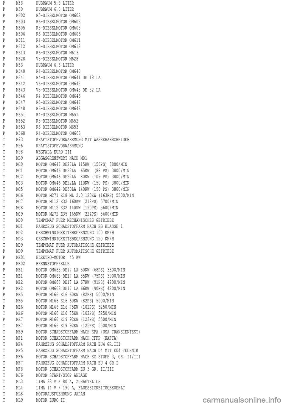
T MJ6 MOTOR START/STOP ANLAGE
T ML3 LIMA 28V/80A,ZUSAETZLICH
T ML4 LIMA 14 V / 190 A, FLUESSIGKEITSGEKUEHLT
T ML8 MOTORAUSFUEHRUNG JAPAN
T ML9 MOTOR EURO II
Page 3835 of 4133

SI18.00-P-0010A
Service Information: oil sludge
26.3.01
ENGINE
111 in MODELS 124, 163, 170, 202, 203, 208, 210
ENGINE
112 in MODELS 129, 163, 170, 202, 203, 208, 210, 220
ENGINE
112, 113 in MODEL 463
ENGINE
113 in MODELS 129, 163, 202, 208, 210, 215, 220
ENGINE
137 in MODEL 215, 220
ENGINE
166 in MODEL 168
Oil sludging in gasoline engines with ASSYST maintenance
system
Recently we have determined that time and time again oil
sludging occurs in gasoline engines with an ASSYST maintenance
system.
Oil sludging can lead to the following complaints:
D
engine oil consumption
D
engine smoke (white/blue)
D
influencing of oil level indicator
D
clogged oil filter, engine oil thickened like jelly
D
Check engine lamp illuminated
D
oil sludge visible during assembly job, e.g. in oil filter, in cylinder
head covers, condensation sludging
(engine 166) etc.
-----------------------------------------------------------------------------------------
The following list of causes may lead individually or as a combination
to engine oil sludging:
D
Crankcase ventilation inoperable, function orifices, bores,
passages in cylinder head cover, cylinder head, crankcase etc.
are mechanically sealed. A nonfunctioning crankcase
ventilation boosts loads on the engine oil through organic
nitrates. The risk of oil sludging increases.
The mechanical condition of the engine is always to be
checked, i.e. all engine oil drain orifices on the cylinder head
and crankcase and all crankcase ventilation ducts must be free
of obstacles. Crankcase breather lines may not be kinked.
Check the ventilation bores in the cylinder head covers.
-----------------------------------------------------------------------------------------
D
The engine oil used does not comply with the specifications in
Sheet 229.1 or 229.3 of the Specifications for Service Products.
The additive process, e.g. dirt-carrying capability, neutralization
capability and oxidation resistance as well as the quality of the
base stock influence sludging time.
Use of engine oils with best possible resistance to formation of
sludge, i.e. use only tested and approved engine oils (from
Sheet 229.1 or 229.3). The best protection is afforded by the
engine oils on Sheet 229.3, which fulfill more stringent
specifications with regard to preventing sludge and deposits
(see Sheet 221.0, page 11). These oils have a distinctly better
anti-sludge characteristic than other engine oils.
D
Sludging after adding a fuel or engine oil special additive.
Do not use fuel or engine oil special additives. More information
hereto is available on Sheet 219.0 of the Specifications for
Service products. Reference to customer not to use special
additives.
D
Engine oil change not performed according to ASSYST
specifications. At driven distances
exceeding > approx. 3000 km, engine oil sludging may occur.
-----------------------------------------------------------------------------------------
Comply with engine oil and filter change as under ASSYST
specifications. Observe remaining distance.
D
Fuel grade lies outside standard (regionally contingent). If
contaminated, deficient fuel is used, then engine oil sludging
may occur even where approved engine oil is used.
Operation with fuel, e.g. as under DIN EN 228. Clarify refueling
behavior of customer. If engine operation regional, is
temporarily possible with deficient oil only, then the startup
distance has to be individually reduced, i.e. the oil change
temporarily performed at an interval of, e.g. 10,000 km.
D
Radiator antifreeze penetration into engine oil, e.g. through an
internal engine leak (cylinder head gasket, casting porosity).
The engine oil sludges within a short period. The crankcase
ventilation clogs up and stops functioning. Condensation
sludging clogs up the oil separator cells
(engine 166).
Rectify coolant leakage. Clean all sludged engine parts, in
particular the crankcase ventilation parts. If the occurrence
repeats, and casting porosity is suspected, e.g. replace
crankcase.
-----------------------------------------------------------------------------------------
Copyright DaimlerChrysler AG 20.05.2006 CD-Ausgabe G/10/04 . This WIS print-out will not be recorde
d by Modification services.
Page 1
Page 3885 of 4133
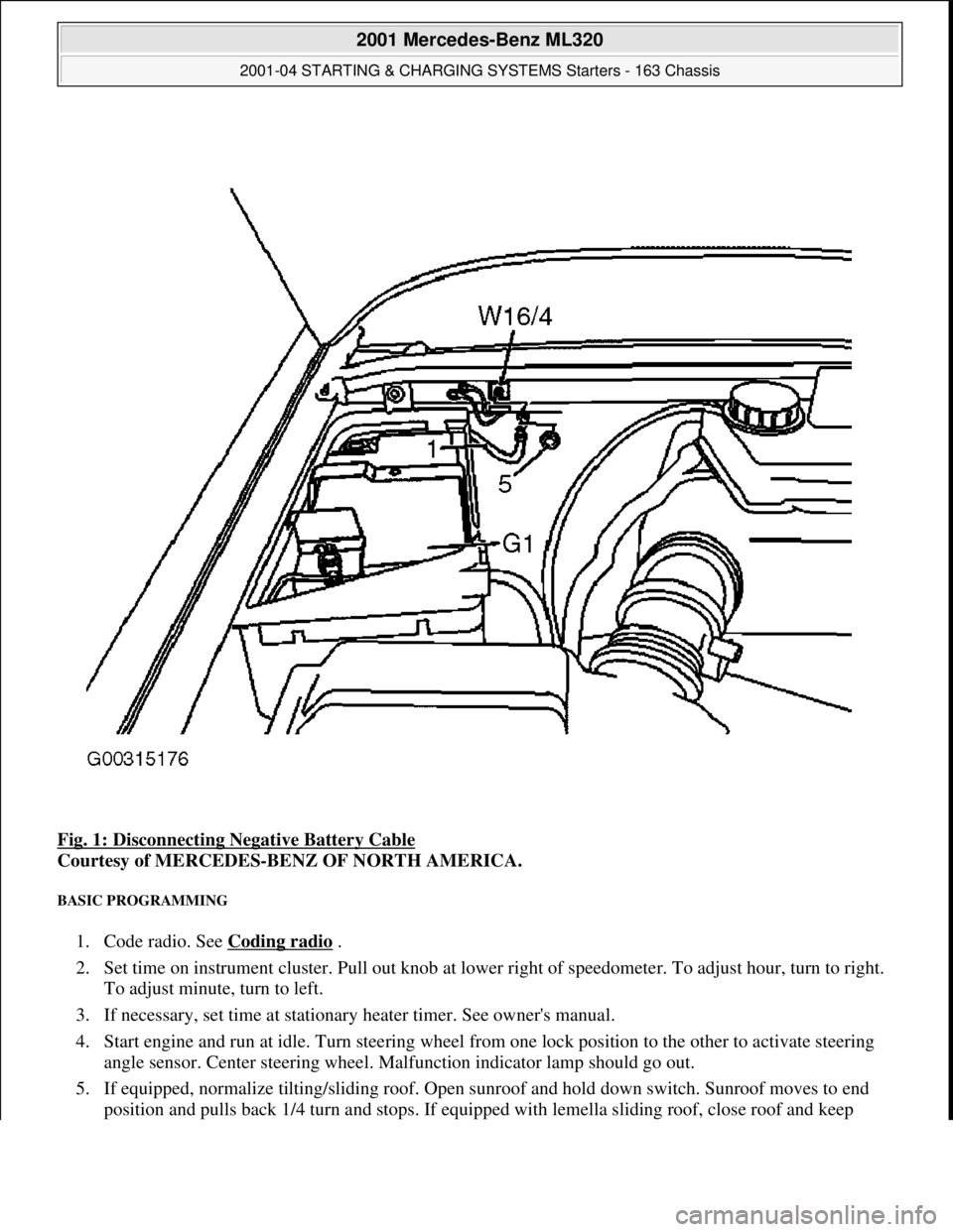
Fig. 1: Disconnecting Negative Battery Cable
Courtesy of MERCEDES-BENZ OF NORTH AMERICA.
BASIC PROGRAMMING
1. Code radio. See Coding radio .
2. Set time on instrument cluster. Pull out knob at lowe r right of speedometer. To adjust hour, turn to right.
To adjust minute, turn to left.
3. If necessary, set time at stationary heater timer. See owner's manual.
4. Start engine and run at idle. Turn steering wheel fr om one lock position to the other to activate steering
angle sensor. Center steering wheel. Ma lfunction indicator lamp should go out.
5. If equipped, normalize ti lting/sliding roof. Open sunroof and hold down switch. Sunroof moves to end
position and pulls back 1/4 turn and stops. If equipped with lemella slidin
g roof, close roof and keep
2001 Mercedes-Benz ML320
2001-04 STARTING & CHARGING SYSTEMS Starters - 163 Chassis
me
Saturday, October 02, 2010 3:19:47 PMPage 3 © 2006 Mitchell Repair Information Company, LLC.
Page 3901 of 4133
GF54.30-P-3009A
Stepper motor, location/design/function
7.7.99
MODEL
129, 140 as of 1.6.96,
163, 168, 170,
202 as of 1.8.96,
208,
210 as of 1.6.96,
215, 220
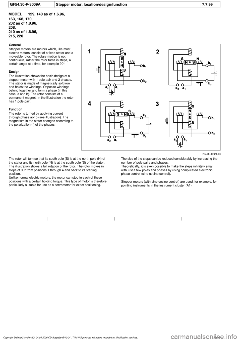
P54.30-0521-06
General
Stepper motors are motors which, like most
electric motors, consist of a fixed stator and a
moveable rotor. The rotary motion is not
continuous, rather the rotor turns in steps, a
certain angle at a time, for example 90°.
Design
The illustration shows the basic design of a
stepper motor with 1 pole pair and 2 phases.
The stator is made of magnetically soft iron
and holds the windings. Opposite windings
belong together and form a phase (in this
case, a and b). The rotor consists of a
permanent magnet. In the illustration the rotor
has 1 pole pair.
Function
The rotor is turned by applying current
through phase aor b (see illustration). The
magnetism in the stator changes according to
the polarization (I) of the phases.
The rotor will turn so that its south pole (S) is at the north pole (N) of
the stator and its north pole (N) is at the south pole (S) of the stator.
The illustration shows a full rotation of the rotor. The rotor moves in
steps of 90° from positions 1 through 4 and back to its starting
position.
Unlike normal electric motors, the motor can stop in each of these
positions with a certain holding torque. This type of motor is therefore
particularly suitable for use as a servomotor for exact positioning.
The size of the steps can be reduced considerably by increasing the
number of pole pairs and phases.
Theoretically, it is even possible to make the steps infinitely small
with just a few poles and phases by using complicated electronic
phase control (sine-cosine control).
Stepper motors (with sine-cosine control) are used, for example, for
pointing instruments in the instrument cluster (A1).
Copyright DaimlerChrysler AG 04.06.2006 CD-Ausgabe G/10/04 . This WIS print-out will not be recorde
d by Modification services.
Page 1
Page 3908 of 4133
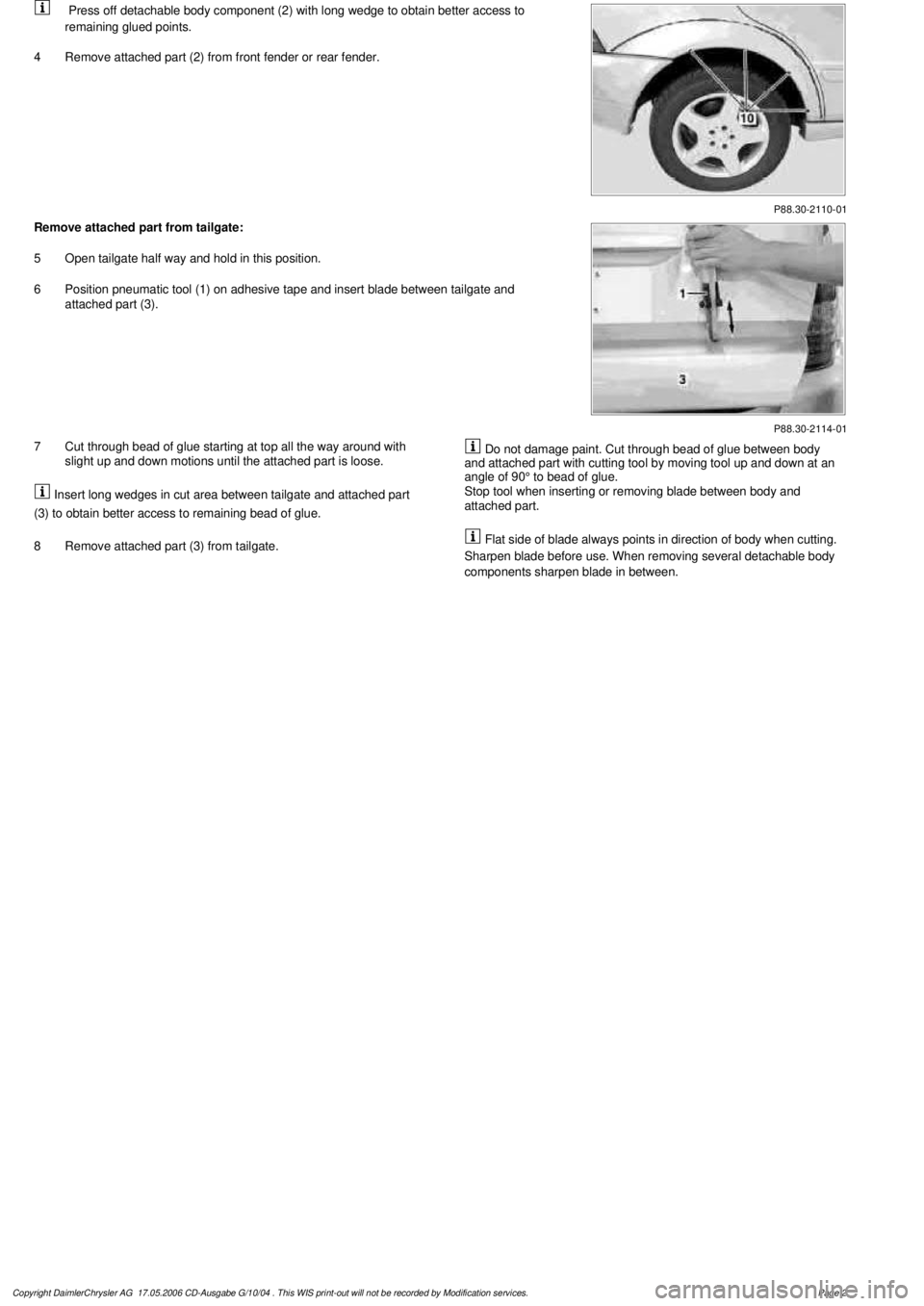
P88.30-2110-01
Press off detachable body component (2) with long wedge to obtain better access to
remaining glued points.
4
Remove attached part (2) from front fender or rear fender.
P88.30-2114-01
Remove attached part from tailgate:
5
Open tailgate half way and hold in this position.
6
Position pneumatic tool (1) on adhesive tape and insert blade between tailgate and
attached part (3).
7
Cut through bead of glue starting at top all the way around with
slight up and down motions until the attached part is loose.
Insert long wedges in cut area between tailgate and attached part
(3) to obtain better access to remaining bead of glue.
8
Remove attached part (3) from tailgate.
Do not damage paint. Cut through bead of glue between body
and attached part with cutting tool by moving tool up and down at an
angle of 90° to bead of glue.
Stop tool when inserting or removing blade between body and
attached part.
Flat side of blade always points in direction of body when cutting.
Sharpen blade before use. When removing several detachable body
components sharpen blade in between.
Copyright DaimlerChrysler AG 17.05.2006 CD-Ausgabe G/10/04 . This WIS print-out will not be recorde
d by Modification services.
Page 2