Page 1879 of 4133
Fig. 299: Identifying Center Console, Auxiliary Interface Module And Retaining Spring
RETROFIT VIDEO PLAYER - AZ82.60-P-0004-05A
Model 163.136 /154 /172 #A as of 145273, Models 163.136 /154 /172 #X as of 708319, Models
163.113/128 /157 /174 /175
Rear seats
1. Unscrew rear nut (1) and bolt (2) from 60% rear seat.
2. Position bracket (3)and secure with bolt (2) and nut (1) .
Insert bolt with Loctite. Replace nut.
3. Install covers under the 60% rear bench.
Replace center cover at rear seat bench at bottom with cover from the conversion kit. Do NOT install
shade at front at the 60% bench.
NumberDesignationModel 163 as of 09/99
BA91.12-P-1005-03ANuts for rear seat console
on vehicle floorNM40
BA91.12-P-1008-03AScrews for rear seat
console on vehicle floorNM40
2001 Mercedes-Benz ML320
1998-2005 ACCESSORIES & BODY, CAB Electrical System - Body - 163 Chassis
me
Saturday, October 02, 2010 3:30:12 PMPage 384 © 2006 Mitchell Repair Information Company, LLC.
Page 1885 of 4133
Fig. 307: Identifying Wiring Harness Fo r Auxiliary Interface Module And Clip
Fig. 308: Identifying Auxiliary Interface Module Connector And Mount For Center Console
Remove
1Remove center console
Remove/install center
console AR68.20-P-2000GH
2Remove center console
insulating mat
3Remove rear air duct Up to VIN A289564,
X754619. 2 screws at
rear air duct.
4Remove radio (A2)
Remove/install radio AR82.60-P-7502EA
5Remove glove
compartment
2001 Mercedes-Benz ML320
1998-2005 ACCESSORIES & BODY, CAB Electr ical System - Body - 163 Chassis
me
Saturday, October 02, 2010 3:30:12 PMPage 390 © 2006 Mitchell Repair Information Company, LLC.
Page 1887 of 4133

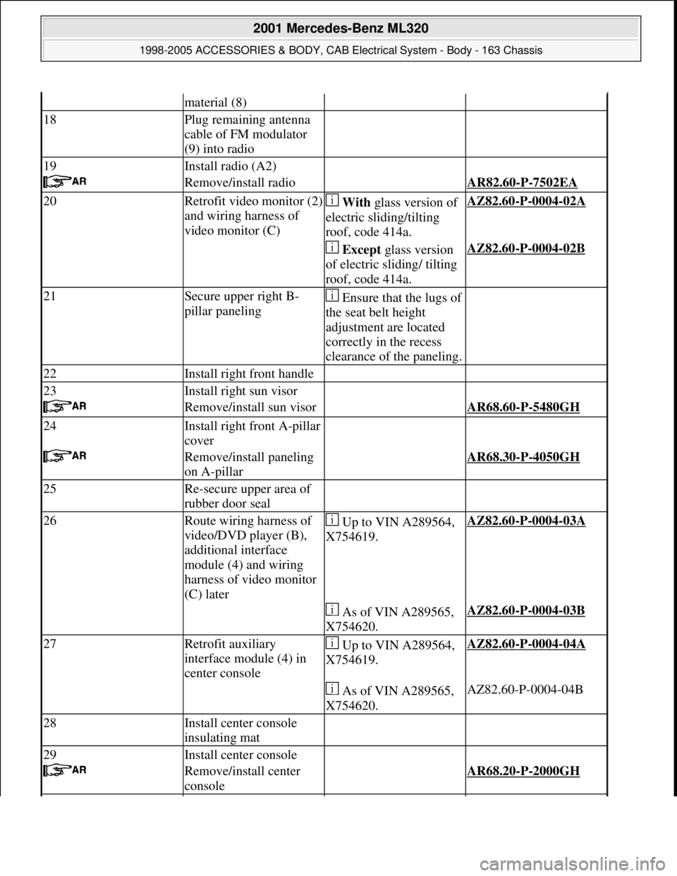
material (8)
18Plug remaining antenna
cable of FM modulator
(9) into radio
19Install radio (A2)
Remove/install radio AR82.60-P-7502EA
20Retrofit video monitor (2)
and wiring harness of
video monitor (C) With glass version of
electric sliding/tilting
roof, code 414a.AZ82.60-P-0004-02A
Except glass version
of electric sliding/ tilting
roof, code 414a.AZ82.60-P-0004-02B
21Secure upper right B-
pillar paneling Ensure that the lugs of
the seat belt height
adjustment are located
correctly in the recess
clearance of the paneling.
22Install right front handle
23Install right sun visor
Remove/install sun visor AR68.60-P-5480GH
24Install right front A-pillar
cover
Remove/install paneling
on A-pillar AR68.30-P-4050GH
25Re-secure upper area of
rubber door seal
26Route wiring harness of
video/DVD player (B),
additional interface
module (4) and wiring
harness of video monitor
(C) later Up to VIN A289564,
X754619.AZ82.60-P-0004-03A
As of VIN A289565,
X754620.AZ82.60-P-0004-03B
27Retrofit auxiliary
interface module (4) in
center console Up to VIN A289564,
X754619.AZ82.60-P-0004-04A
As of VIN A289565,
X754620.AZ82.60-P-0004-04B
28Install center console
insulating mat
29Install center console
Remove/install center
console AR68.20-P-2000GH
2001 Mercedes-Benz ML320
1998-2005 ACCESSORIES & BODY, CAB Electrical System - Body - 163 Chassis
me
Saturday, October 02, 2010 3:30:12 PMPage 392 © 2006 Mitchell Repair Information Company, LLC.
Page 1888 of 4133

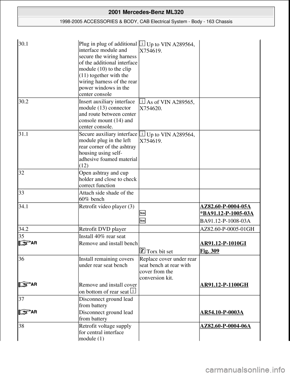
30.1Plug in plug of additional
interface module and
secure the wiring harness
of the additional interface
module (10) to the clip
(11) together with the
wiring harness of the rear
power windows in the
center console Up to VIN A289564,
X754619.
30.2Insert auxiliary interface
module (13) connector
and route between center
console mount (14) and
center console. As of VIN A289565,
X754620.
31.1Secure auxiliary interface
module plug in the left
rear corner of the ashtray
housing using self-
adhesive foamed material
(12) Up to VIN A289564,
X754619.
32Open ashtray and cup
holder and close to check
correct function
33Attach side shade of the
60% bench
34.1Retrofit video player (3) AZ82.60-P-0004-05A
*BA91.12-P-1005-03A
BA91.12-P-1008-03A
34.2Retrofit DVD player AZ82.60-P-0005-01GH
35Install 40% rear seat
Remove and install bench AR91.12-P-1010GI
Torx bit setFig. 309
36Install remaining covers
under rear seat benchReplace cover under rear
seat bench at rear with
cover from the
conversion kit.
Remove and install cover
on bottom of rear seat AR91.12-P-1100GH
37Disconnect ground lead
from battery
Disconnect ground lead
from battery AR54.10-P-0003A
38Retrofit voltage supply
for central interface
module (1) AZ82.60-P-0004-06A
2001 Mercedes-Benz ML320
1998-2005 ACCESSORIES & BODY, CAB Electrical System - Body - 163 Chassis
me
Saturday, October 02, 2010 3:30:12 PMPage 393 © 2006 Mitchell Repair Information Company, LLC.
Page 2041 of 4133

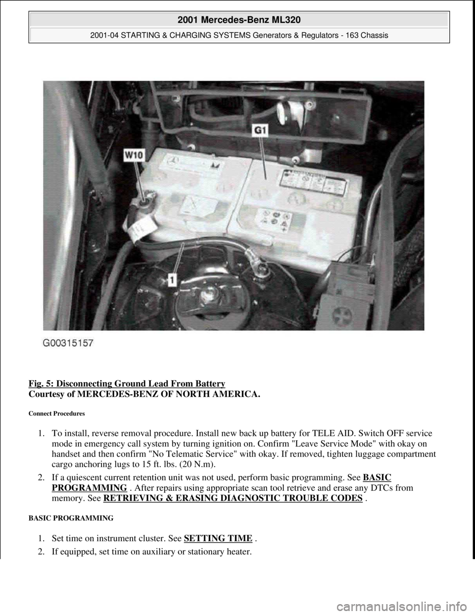
Fig. 5: Disconnecting Ground Lead From Battery
Courtesy of MERCEDES-BENZ OF NORTH AMERICA.
Connect Procedures
1. To install, reverse removal procedure. Install new back up battery for TELE AID. Switch OFF service
mode in emergency call system by turning ignition on. Confirm "Leave Service Mode" with okay on
handset and then confirm "No Telematic Service" with okay. If removed, tighten luggage compartment
cargo anchoring lugs to 15 ft. lbs. (20 N.m).
2. If a quiescent current retention unit was not used, perform basic programming. See BASIC
PROGRAMMING . After repairs using appropriate scan tool retrieve and erase any DTCs from
memory. See RETRIEVING & ERASING DIAGNOSTIC TROUBLE CODES
.
BASIC PROGRAMMING
1. Set time on instrument cluster. See SETTING TIME .
2. If equipped, set time on auxiliary or stationary heater.
2001 Mercedes-Benz ML320
2001-04 STARTING & CHARGING SYSTEMS Generators & Regulators - 163 Chassis
me
Saturday, October 02, 2010 3:20:32 PMPage 7 © 2006 Mitchell Repair Information Company, LLC.
Page 2092 of 4133
001 589 72 21 00
Torque wrench
Pressure hose
119 589 04 63 00
Commercially available tools
(see Workshop Equipment Manual)
Number
Designation
Make (e. g.)
Order number
WH58.30-Z-1001-06A
6 mm socket hexagon on flexible shaft for hose clamps with worm drive
Hazet
Güldenwerther
Bahnhofstraße 25-28
D-42857 Remscheid
426-6
WH58.30-Z-1002-06A
7 mm hexagon socket wrench to flexible shaft for hose clips with worm
drive
Hazet
Güldenwerther
Bahnhofstraße 25-28
D-42857 Remscheid
426-7
Auxiliary repair materials
Number
Designation
Order number
BR00.45-Z-1015-01A
Loctite sealant 5970A 003 989 98 20 10
Copyright DaimlerChrysler AG 20.05.2006 CD-Ausgabe G/10/04 . This WIS print-out will not be recorde
d by Modification services.
Page 8
Page 2100 of 4133
001 589 72 21 00
Torque wrench
Pressure hose
119 589 04 63 00
Commercially available tools
(see Workshop Equipment Manual)
Number
Designation
Make (e. g.)
Order number
WH58.30-Z-1001-06A
6 mm socket hexagon on flexible shaft for hose clamps with worm drive
Hazet
Güldenwerther
Bahnhofstraße 25-28
D-42857 Remscheid
426-6
WH58.30-Z-1002-06A
7 mm hexagon socket wrench to flexible shaft for hose clips with worm
drive
Hazet
Güldenwerther
Bahnhofstraße 25-28
D-42857 Remscheid
426-7
Auxiliary repair materials
Number
Designation
Order number
BR00.45-Z-1015-01A
Loctite sealant 5970A 003 989 98 20 10
Copyright DaimlerChrysler AG 20.05.2006 CD-Ausgabe G/10/04 . This WIS print-out will not be recorde
d by Modification services.
Page 8
Page 2110 of 4133

AR72.10-P-2100GH
Remove/install door catch
11.2.97
MODEL
163.113 /128 /136 /154 /157 /172 /174 /175
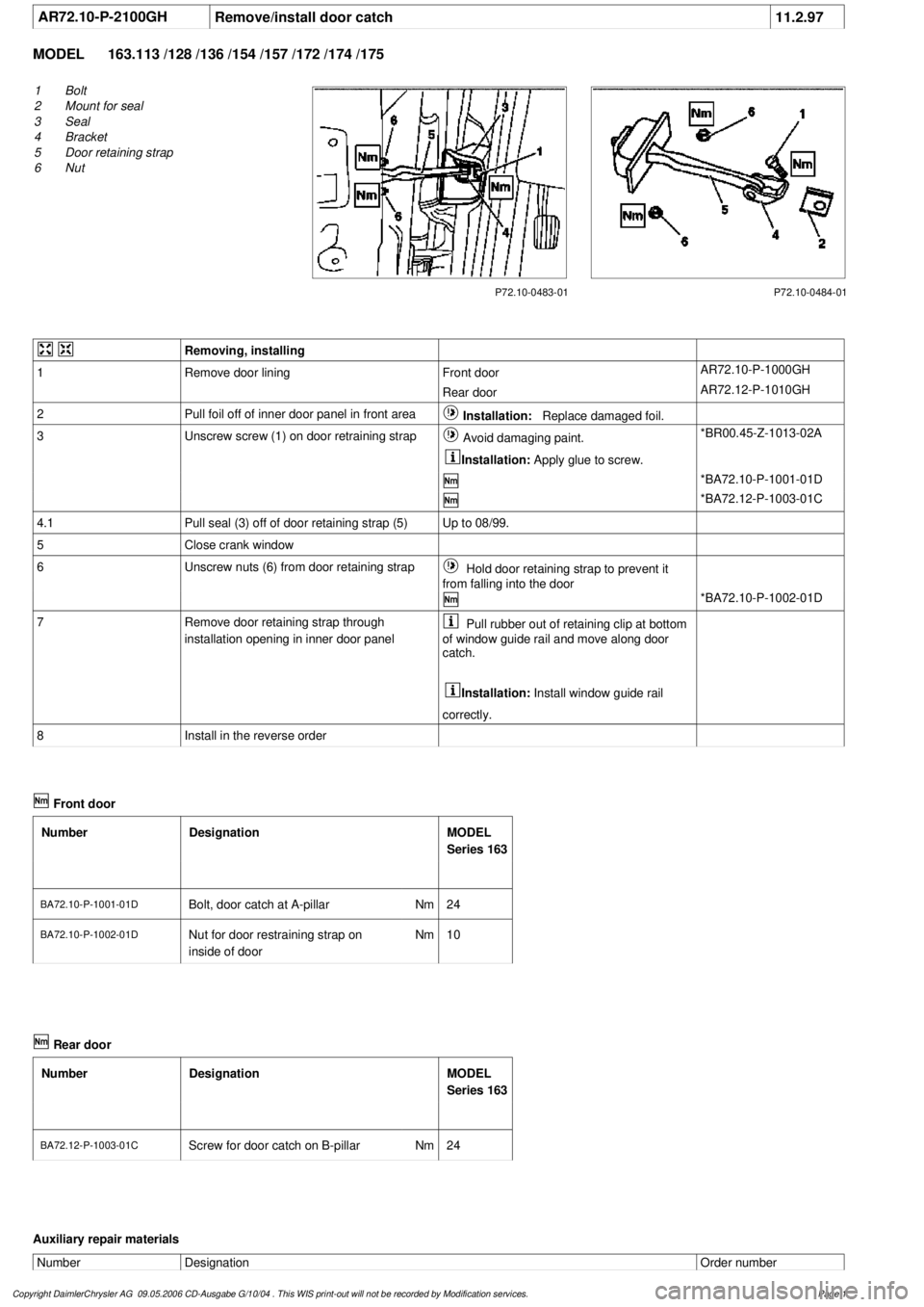
P72.10-0483-01
1
Bolt
2
Mount for seal
3
Seal
4
Bracket
5
Door retaining strap
6
Nut
P72.10-0484-01
Removing, installing
1
Remove door lining
Front door
AR72.10-P-1000GH
Rear door
AR72.12-P-1010GH
2
Pull foil off of inner door panel in front area
Installation:
Replace damaged foil.
3
Unscrew screw (1) on door retraining strap
Avoid damaging paint.
Installation:
Apply glue to screw.
*BR00.45-Z-1013-02A
*BA72.10-P-1001-01D
*BA72.12-P-1003-01C
4.1
Pull seal (3) off of door retaining strap (5)
Up to 08/99.
5
Close crank window
6
Unscrew nuts (6) from door retaining strap
Hold door retaining strap to prevent it
from falling into the door
*BA72.10-P-1002-01D
7
Remove door retaining strap through
installation opening in inner door panel
Pull rubber out of retaining clip at bottom
of window guide rail and move along door
catch.
Installation:
Install window guide rail
correctly.
8
Install in the reverse order
Front door
Number
Designation
MODEL
Series 163
BA72.10-P-1001-01DBolt, door catch at A-pillar
Nm
24
BA72.10-P-1002-01D
Nut for door restraining strap on
inside of door
Nm
10
Rear door
Number
Designation
MODEL
Series 163
BA72.12-P-1003-01C
Screw for door catch on B-pillar
Nm
24
Auxiliary repair materials
Number
Designation
Order number
Copyright DaimlerChrysler AG 09.05.2006 CD-Ausgabe G/10/04 . This WIS print-out will not be recorde
d by Modification services.
Page 1