Page 1759 of 4133

INSTALLING AUXILIARY CABLE HARNESS ON SIDE WALL TAILLAMP - AR82.10-P-4920-01GH
Models 163.154/174 as of VINA289565 to VIN A371934, model 163.175 up to VIN A371934 with USA
version code 494a
1. Insert plug (1) of auxiliary cable harness (2) in socket (3) of side-marker lamp.
2. Insert the plug on the other end of the wiring harness in the free connection pins in the opening (4) of the
lamp support (5).
The brown line (ground) should be on the outside. Ensure that the plugs are completely pushed onto
the connection pins.
3. Seal the lines and opening (4) with a thermoplastic adhesive gun.
Give the adhesive sufficient time to dr
y before installing the taillamp.
distance of the cover to
the bumper is even.
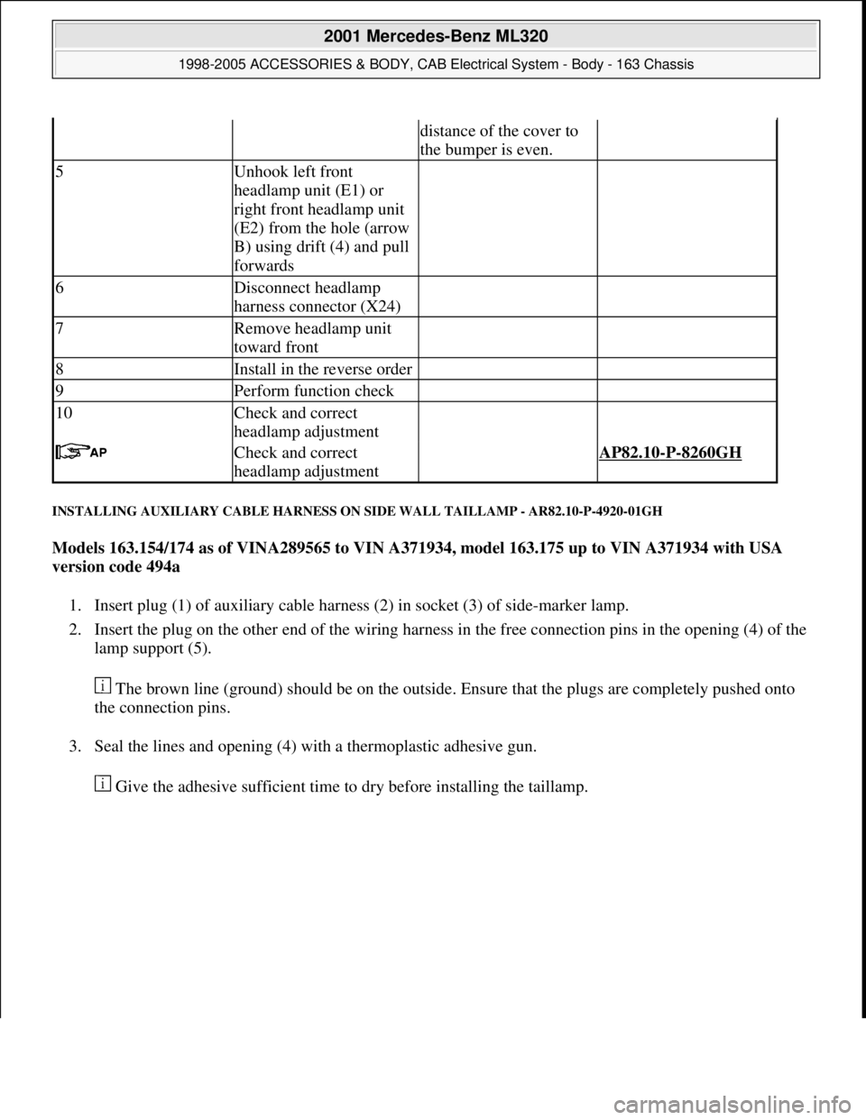
5Unhook left front
headlamp unit (E1) or
right front headlamp unit
(E2) from the hole (arrow
B) using drift (4) and pull
forwards
6Disconnect headlamp
harness connector (X24)
7Remove headlamp unit
toward front
8Install in the reverse order
9Perform function check
10Check and correct
headlamp adjustment
Check and correct
headlamp adjustment AP82.10-P-8260GH
2001 Mercedes-Benz ML320
1998-2005 ACCESSORIES & BODY, CAB Electrical System - Body - 163 Chassis
me
Saturday, October 02, 2010 3:30:09 PMPage 264 © 2006 Mitchell Repair Information Company, LLC.
Page 1760 of 4133
Fig. 164: Identifying Auxiliary Cabl e Harness On Side Wall Taillamp
REMOVE/INSTALL SIDE WALL TAILLAMP - AR82.10-P-4920GH
MODEL 163
Fig. 165: Identifying Side Wall Taillamp
Remove/Install
2001 Mercedes-Benz ML320
1998-2005 ACCESSORIES & BODY, CAB Electr ical System - Body - 163 Chassis
me
Saturday, October 02, 2010 3:30:09 PMPage 265 © 2006 Mitchell Repair Information Company, LLC.
Page 1761 of 4133
REMOVE/INSTALL FOG LAMP - AR82.10-P-5103GH
MODEL 163.113 /128 /136 /154 /157 /172 /175 with CODE (U49) Styling package
MODEL 163.174
Fig. 166: Identifying Fog Lamp Components
1Open rear flap
2Unscrew nuts(1)
3Pull back left taillamp
(E3) or right taillamp (E4) Installation: Insert
spigot (2) in the support
(3).
4Unplug connector (4)
5Take out taillamp
6.1Install auxiliary wiring
harness Only if the taillamp is
replaced. Only on USA
version vehicles, code
494a and as of VIN
A289565 up to A371934.AR82.10-P-4920-01GH
7Install in the reverse order
8Perform function check
Remove/Install
2001 Mercedes-Benz ML320
1998-2005 ACCESSORIES & BODY, CAB Electrical System - Body - 163 Chassis
me
Saturday, October 02, 2010 3:30:09 PMPage 266 © 2006 Mitchell Repair Information Company, LLC.
Page 1870 of 4133
Fig. 288: Identifying Video Display, Video Monitor Unit And Remote Control Storage
Compartment
RETROFIT WIRING HARNESS FOR AUXILIARY INTERFACE MODULE AND VIDEO/DVD PLAYER - AZ82.60-P-0004-
03A
Model 163.113/136 /154 /172 /174 #A as of 145273 289564,
Model 163.113 /136 /154 /172 #X as of 708319 up to 754619
1. Adhere supplied self-adhesive foamed material (1) to rear end of the center console bracket (2).
2. Measure dimension (a) on left and right from the upper edge of the transmission tunnel and mark floor
covering.
3. Starting from the transmission tunnel cutout of the floor covering, cut into floor covering 2 times (b).
Incisions should be located above the recesses in the transmission tunnel.
2001 Mercedes-Benz ML320
1998-2005 ACCESSORIES & BODY, CAB Electrical System - Body - 163 Chassis
me
Saturday, October 02, 2010 3:30:12 PMPage 375 © 2006 Mitchell Repair Information Company, LLC.
Page 1872 of 4133

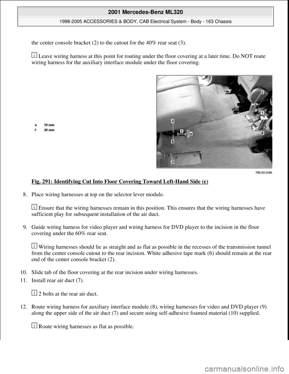
the center console bracket (2) to the cutout for the 40% rear seat (3).
Leave wiring harness at this point for routing under the floor covering at a later time. Do NOT route
wiring harness for the auxiliary interface module under the floor covering.
Fig. 291: Identifying Cut Into Floor Covering Toward Left
-Hand Side (e)
8. Place wiring harnesses at top on the selector lever module.
Ensure that the wiring harnesses remain in this position. This ensures that the wiring harnesses have
sufficient play for subsequent installation of the air duct.
9. Guide wiring harness for video player and wiring harness for DVD player to the incision in the floor
covering under the 60% rear seat.
Wiring harnesses should lie as straight and as flat as possible in the recesses of the transmission tunnel
from the center console cutout to the rear incision. White adhesive tape mark (6) should remain at the rear
end of the center console bracket (2).
10. Slide tab of the floor covering at the rear incision under wiring harnesses.
11. Install rear air duct (7).
2 bolts at the rear air duct.
12. Route wiring harness for auxiliary interface module (8), wiring harnesses for video and DVD player (9)
along the upper side of the air duct (7) and secure using self-adhesive foamed material (10) supplied.
Route wirin
g harnesses as flat as possible.
2001 Mercedes-Benz ML320
1998-2005 ACCESSORIES & BODY, CAB Electrical System - Body - 163 Chassis
me
Saturday, October 02, 2010 3:30:12 PMPage 377 © 2006 Mitchell Repair Information Company, LLC.
Page 1873 of 4133
Fig. 292: Identifying Rear Air Duct, Self-Adhesive Foamed Material And Auxiliary Interface
Module
13. Secure wiring harness for auxiliary interface module (8) with tie straps (12) to wiring harness of the rear
power window (11).
White adhesive tape marks identify position of the tie straps.
14. Secure video player wiring harness with blue color coding (4) and DVD player wiring harness with red
color coding (5) with self-adhesive brackets (13) and tie straps at the 60% rear seat.
The white strips of adhesive tape on the wiring harness for video player (4) and the red strips of
adhesive tape on the wiring harness for DVD player (5) identify the location for the brackets and tie
straps.
2001 Mercedes-Benz ML320
1998-2005 ACCESSORIES & BODY, CAB Electrical System - Body - 163 Chassis
me
Saturday, October 02, 2010 3:30:12 PMPage 378 © 2006 Mitchell Repair Information Company, LLC.
Page 1874 of 4133
Fig. 293: Identifying Self-Adhesive Brackets, Blue Color Coding And Red Color Coding
RETROFIT WIRING HARNESS FOR AUXILIARY INTERFACE MODULE AND VIDEO/DVD PLAYER - AZ82.60-P-0004-03B
Models 163.113/154/174#A as of 289565, Model 163.113 #X as of 754620, Model 163.128/157/175
1. Make diagonal cut (a=50 mm) to floor lining of right rear corner of rear blower motor (M2/1).
Fig. 294: Identifying Rear Blower Motor, Cutout In Floor Lining And DVD Player Wiring Harness
2. Measure dimension (b=510 mm) from center of rear blower motor (M2/1) and dimension (c=120 mm)
from inner edge of cutout in floor lining under the 40% rear seat and mark the floor lining.
2001 Mercedes-Benz ML320
1998-2005 ACCESSORIES & BODY, CAB Electrical System - Body - 163 Chassis
me
Saturday, October 02, 2010 3:30:12 PMPage 379 © 2006 Mitchell Repair Information Company, LLC.
Page 1878 of 4133

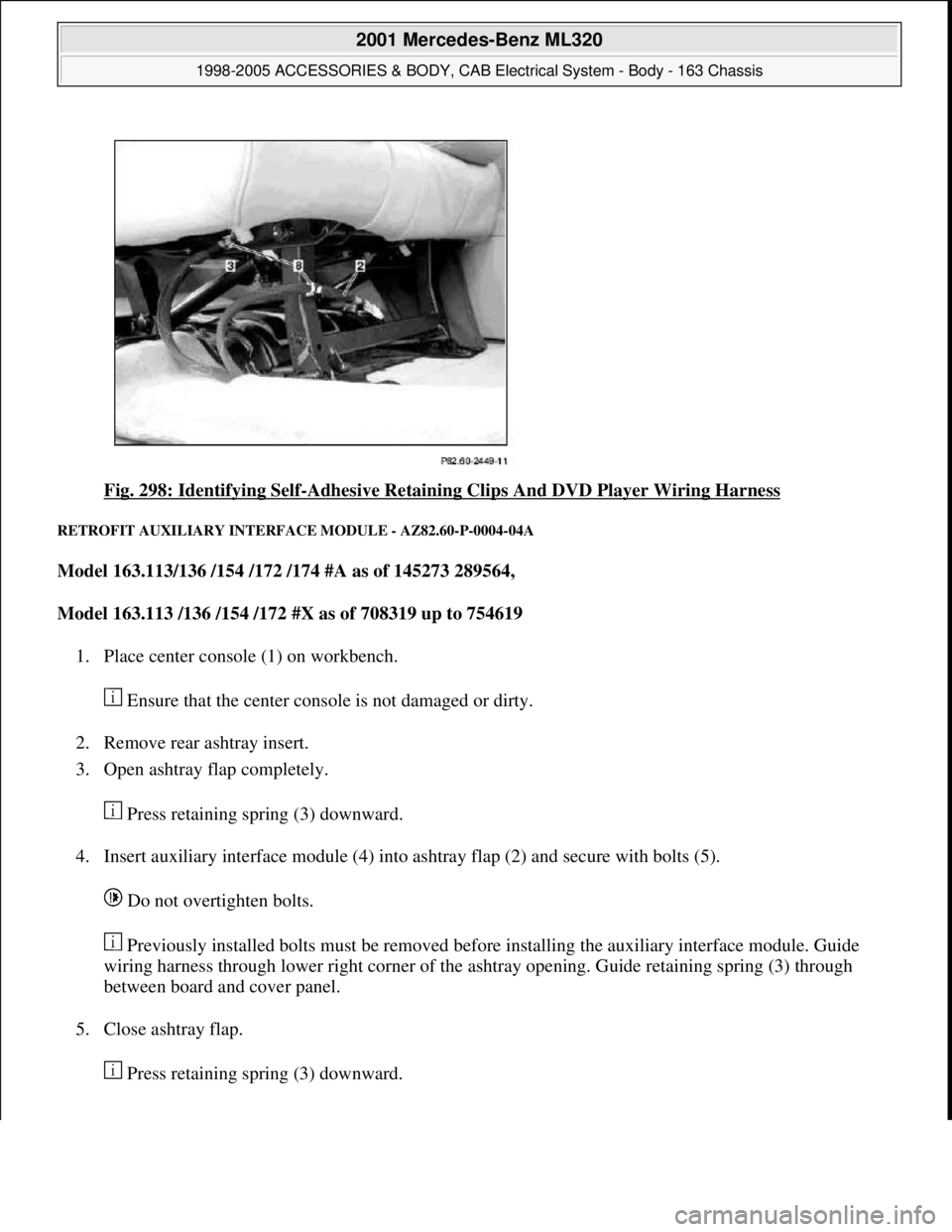
Fig. 298: Identifying Self-Adhesive Retaining Clips And DVD Player Wiring Harness
RETROFIT AUXILIARY INTERFACE MODULE - AZ82.60-P-0004-04A
Model 163.113/136 /154 /172 /174 #A as of 145273 289564,
Model 163.113 /136 /154 /172 #X as of 708319 up to 754619
1. Place center console (1) on workbench.
Ensure that the center console is not damaged or dirty.
2. Remove rear ashtray insert.
3. Open ashtray flap completely.
Press retaining spring (3) downward.
4. Insert auxiliary interface module (4) into ashtray flap (2) and secure with bolts (5).
Do not overtighten bolts.
Previously installed bolts must be removed before installing the auxiliary interface module. Guide
wiring harness through lower right corner of the ashtray opening. Guide retaining spring (3) through
between board and cover panel.
5. Close ashtray flap.
Press retainin
g spring (3) downward.
2001 Mercedes-Benz ML320
1998-2005 ACCESSORIES & BODY, CAB Electrical System - Body - 163 Chassis
me
Saturday, October 02, 2010 3:30:12 PMPage 383 © 2006 Mitchell Repair Information Company, LLC.