1997 MERCEDES-BENZ ML350 light
[x] Cancel search: lightPage 1358 of 4133
Fig. 108: Selector Lever Positions
Courtesy of MERCEDES-BENZ OF NORTH AMERICA.
AUTOMATIC TRANSMISSION, FUNCTION
Transmission With Touch Shift 722.6 In Model 163
Transmission 722.6 is an electronically controlled 5-speed transmission with a lockup clutch in the torque
converter.
The ratios for the gear stages are achieved by 3 planetary gearsets. The 5th gear is designed as a low-rev gear
with an overdrive ratio.
Shifting is initiated electronically. The gears are shifted by the corresponding combination of 3 hydraulically
actuated multi-disk brakes, 3 hydraulically actuated multi-disk clutches and 2 mechanical freewheels.
The oil pump as well as the external plate carrier of the front multi-disk brake are bolted to the torque converter
housing.
The mechanical part of the transmission 722.6 consists of a drive shaft, output shaft, a sun gear shaft and 3
planetary sets which are coupled to each other.
The electrohydraulic control unit is screwed onto the transmission housing from below. The end of the
transmission if formed by an oil pan made of sheet steel.
The oil pressure of the torque converter lockup clutch and center multi-disk clutch is supplied via bore holes in
the drive shaft. The oil pressure to the rear multi-disk clutch is supplied via the output shaft. The lubricating oil
is supplied and distributed by additional bore holes in both shafts. Oil is supplied to all bearing points of the
gearsets as well as to the freewheels and shifting elements.
The parking lock gear and drive flange are connected to the output shaft by gearing.
Basically transmission 722.6 with electronic control offers the following advantages:
Reduced fuel consumption.
Greater ease of shifting.
Favorable spacing by 5 gears.
Long service life and high reliability.
Low maintenance costs.
The torque converter housing and transmission housing consist of a light-metal alloy. Both housings are bolted
together and are centered via the external plate carrier of the multi-disk brake at the front. A coated intermediate
panel seals the two components.
Freewheels F1 and F2 optimize shifting. The front freewheel F1 is supported on the extension of the stator shaft
on the transmission end and connects in the lockin
g direction the sun gear of the front planetary gearset with the
2001 Mercedes-Benz ML320
1998-03 AUTOMATIC TRANSMISSIONS Complete Transmissions - ML 320 - 722.662
me
Saturday, October 02, 2010 3:15:28 PMPage 189 © 2006 Mitchell Repair Information Company, LLC.
Page 1359 of 4133
transmission housing.
The rear freewheel F2 connects in the locking direction the sun gear of the center planetary set with the sun gear
of the rear planetary set. The electrohydraulic control unit is comprised of a light alloy shift plate for the
hydraulic control and an electric control unit.
The electronic control unit consists of a plastic shell which combines all the electric components. The shell is
mounted on and bolted to the shift plate. Conductor tracks which are laid in the supporting body make the
connection between the electrical components and a 13-pin plug socket.
Automatic Transmission, Location Of Mechanical Components
See AUTOMATIC TRANSMISSION, LOCATION OF MECHANICAL PARTS
.
Automatic Transmission, Location Of Electrical/Electronic Components
See AUTOMATIC TRANSMISSION, LOCATION OF ELECTRIC/ELECTRONIC
COMPONENTS.
Automatic Transmission, Location Of Hydraulic Components
See AUTOMATIC TRANSMISSION, POSITION OF HYDRAULIC COMPONENTS
.
Automatic Transmission, Location Of Floor Shift Components.
See AUTOMATIC TRANSMISSION, LOCATION OF FLOOR SHIFT COMPONENTS
.
Automatic Transmission, Selector Lever Positions
See AUTOMATIC TRANSMISSION, SELECTOR LEVER POSITIONS
.
Automatic Transmission, Driver Information
See AUTOMATIC TRANSMISSION, DRIVER INFORMATION
.
Automatic Transmission, Gear Ratios
See AUTOMATIC TRANSMISSION, GEAR RATIOS
.
Power Transmission, Function
See AUTOMATIC TRANSMISSION, POWER TRANSMISSION, FUNCTION
.
Gearshift System, Function
Models 163, 170, 202, 208, 210, 215, 220, 240 (except 215.374/379, 220.074/174/179). See FUNCTION
OF GEAR SHIFT.
2001 Mercedes-Benz ML320
1998-03 AUTOMATIC TRANSMISSIONS Complete Transmissions - ML 320 - 722.662
me
Saturday, October 02, 2010 3:15:28 PMPage 190 © 2006 Mitchell Repair Information Company, LLC.
Page 1467 of 4133
5 - Detach plug (3) from actuator motor.
6 - Support transmission and remove rear engine crossmember (5) with engine mount.
7 - Slightly lower engine transmission unit.
8 - Support transfer case (2) with lifting device. See SUPPORTING TRANSMISSION WITH
INSPECTION PIT LIFT.
9 - Unscrew bolts (4) and take out transfer case to the back.
10 - Install in the reverse order.
11 - Check filling capacity of transfer case.
Check transfer case (2) for leaks.
Torque Specifications; Driveshaft NOTE: Hang up propeller shaft to one side and ensure that the universal joint is
not damaged.
Self-locking bolt, propeller shaft to transfer case (to front axle). See
Torque Specifications; Driveshaft
.
NOTE:
Engine 112:
Bolt of rear engine crossmember to body.
Engine 112:
Bolt or nut, rear engine mount to transmission.
NOTE: Ensure that no lines are damaged.
NOTE: Transmission plate.
NOTE: Bolt, transfer case to automatic transmission.
Bolt, transfer case to manual transmission.
NOTE: Correct oil level: Bottom edge of filler hole.
Screw plug to transfer case.
DesignationModel 163
Self-locking bolt, front propeller shaft to transfer case (to rear axle)Nm40
2001 Mercedes-Benz ML320
1998-03 AUTOMATIC TRANSMISSIONS Complete Transmissions - ML 320 - 722.662
me
Saturday, October 02, 2010 3:15:30 PMPage 298 © 2006 Mitchell Repair Information Company, LLC.
Page 1471 of 4133
Basically automatic transmission 722.6 with electronic control offers the following advantages:
Reduced Fuel Consumption
Improved Shift Comfort
More Favorable Gear Steps As A Result Of 5 Gears
Enhanced Life And Reliability
Reduced Servicing Costs
The electrohydraulic control unit is bolted onto the bottom of the transmission housing. The end of the
transmission is formed by an oil pan made of sheet steel.
The oil pressure for the converter lockup clutch and center multiple-disc clutch is supplied via holes in the input
shaft. The oil pressure to the rear multiple-disc clutch is routed through the output shaft. The lubricating oil is
supplied and distributed by additional bore holes in both shafts. All bearing points of the gear sets as well as
freewheels and shift elements are supplied with lubricating oil.
The parking lock gear and drive flange are connected to the output shaft by gearing.
Freewheels F1 and F2 optimize shifting. The front freewheel (F1) rests against the stator shaft extension on the
transmission side and connects the sun gear of the front planetary gear set to the transmission housing in the
locking direction.
The torque converter housing and transmission housing are made of a metal alloy. They are bolted together and
centered via the outer multiple-disc carrier of the multiple-disc brake B1. A coated intermediate panel seals the
two components.
The oil pump and outer multiple-disc carrier of the front multiple-disc brake are bolted to the converter housing.
The mechanical part consists of the propeller shaft, output shaft, a sun gear shaft and three planetary gearsets
which are coupled together.
In transmissions for powerful engines, the planetary gearsets have 4 planetary gears, while for less powerful
engines the front and rear planetary gear system has three planetary gear wheels. The stator shaft is pressed into
this and is secured against turning by a spline.
The rear freewheel F2 connects the sun gear of the center planetary gear set to the sun gear of the rear planetary
gearset in the locking direction.
The electrohydraulic control unit consists of the shift plate made of light alloy for hydraulic control and an
electronic control unit.
The electrical control unit consists of a supporting body made of plastic in which the electrical components are
combined. The shell is screwed to the shift plate. Conductor tracks which are integrated into the shell, connect
the electric components to a plug connector. This 13-pin plug connector forms the connection with the vehicle-
side wiring harness and with the ETC 5 (electronic transmission control) control module (N15/5) via a bayonet
lock.
2001 Mercedes-Benz ML320
1998-03 AUTOMATIC TRANSMISSIONS Complete Transmissions - ML 320 - 722.662
me
Saturday, October 02, 2010 3:15:30 PMPage 302 © 2006 Mitchell Repair Information Company, LLC.
Page 1507 of 4133
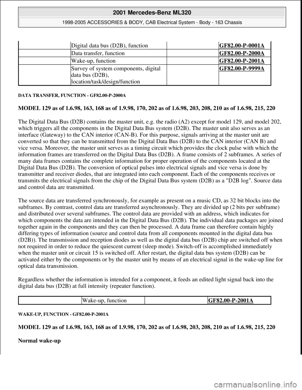
DATA TRANSFER, FUNCTION - GF82.00-P-2000A
MODEL 129 as of 1.6.98, 163, 168 as of 1.9.98, 170, 202 as of 1.6.98, 203, 208, 210 as of 1.6.98, 215, 220
The Digital Data Bus (D2B) contains the master unit, e.g. the radio (A2) except for model 129, and model 202,
which triggers all the components in the Digital Data Bus system (D2B). The master unit also serves as an
interface (Gateway) to the CAN interior (CAN-B). For this purpose, signals arriving at the master unit are
converted so that they can be transmitted from the Digital Data Bus (D2B) to the CAN interior (CAN B) and
vice versa. Moreover, the master unit serves as a timing circuit which provides the clock pulse with which the
information frames are transferred on the Digital Data Bus (D2B). A frame consists of 2 subframes. A series of
many data frames contains the complete information for proper operation of the components located at the
Digital Data Bus (D2B). The conversion of optical pulses into electrical signals and vice versa is done by
transmitter and receiver diodes, that are integrated into each component. Each of the components receives or
transmits the electrical signals from the chip of the Digital Data Bus system (D2B) as a "D2B log". Source data
and control data are transmitted.
The source data are transferred synchronously, for example as present on a music CD, as 32 bit blocks into the
subframes. By contrast, control data are transferred asynchronously. They are divided up (2 bits per subframe)
and distributed over several subframes. The control data are provided with an address, which indicates for
which components the data are intended in the Digital Data Bus (D2B). The individual data packages are joined
together again in the components and they can then be processed. A data frame can therefore contain highly
differing types of information (source and control data from all components mounted in the digital data bus
(D2B)). The transmission and reception diodes as well as the digital data bus (D2B) chip are switched off when
not required in order to reduce the quiescent current (sleep mode). Switch-off is accomplished immediately
when the master unit or circuit 15 is switched off. After restart, the digital data bus system (D2B) can be
activated either by the components or by the master unit by means of an electrical signal in the wake-up line for
optical data transmission.
Regardless whether the information is intended for a component, it feeds an edited light signal back into the
digital data bus (D2B) at full intensity (repeater function).
WAKE-UP, FUNCTION - GF82.00-P-2001A
MODEL 129 as of 1.6.98, 163, 168 as of 1.9.98, 170, 202 as of 1.6.98, 203, 208, 210 as of 1.6.98, 215, 220
Normal wake-up
Digital data bus (D2B), function GF82.00-P-0001A
Data transfer, function GF82.00-P-2000A
Wake-up, function GF82.00-P-2001A
Survey of system components, digital
data bus (D2B),
location/task/design/function GF82.00-P-9999A
Wake-up, function GF82.00-P-2001A
2001 Mercedes-Benz ML320
1998-2005 ACCESSORIES & BODY, CAB Electrical System - Body - 163 Chassis
me
Saturday, October 02, 2010 3:30:04 PMPage 12 © 2006 Mitchell Repair Information Company, LLC.
Page 1509 of 4133
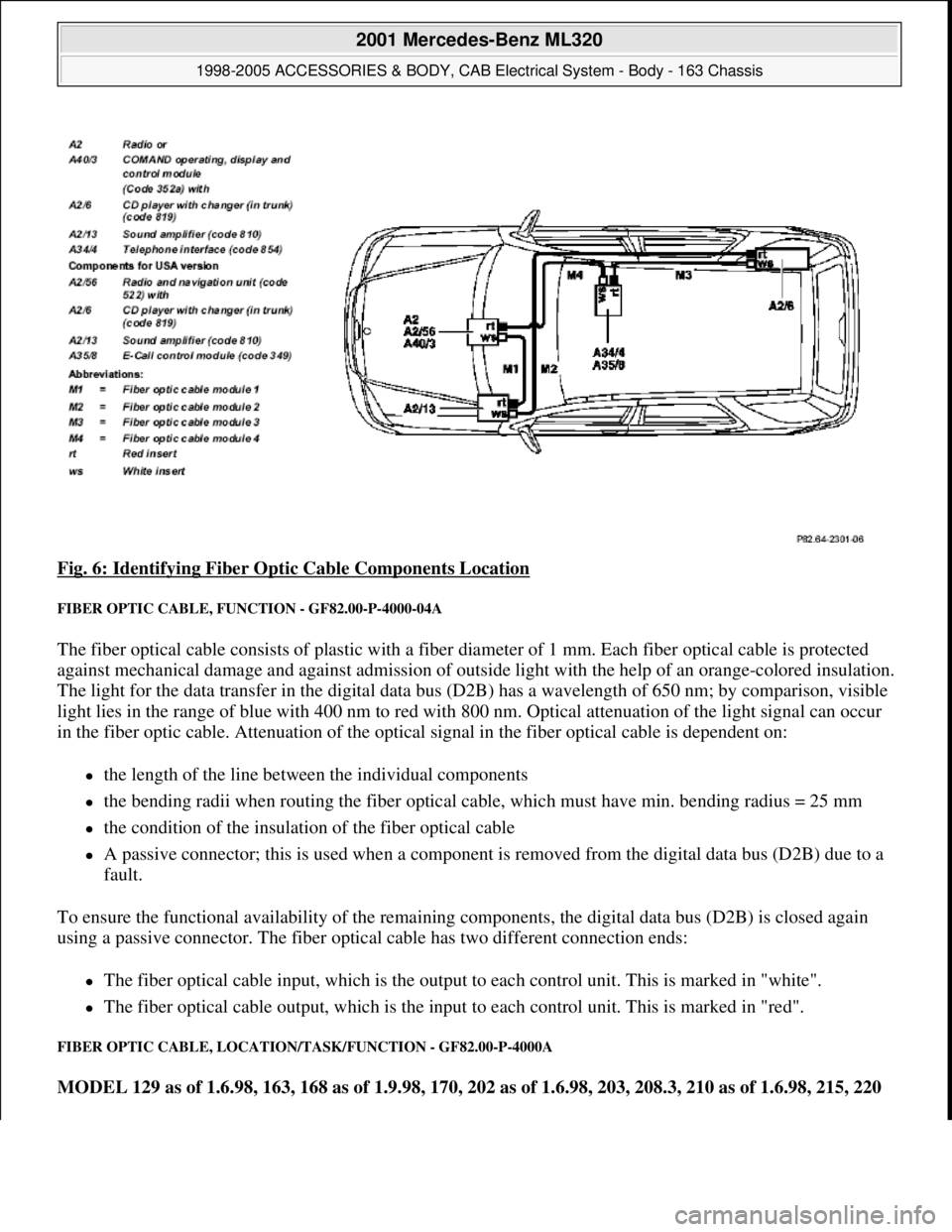
Fig. 6: Identifying Fiber Optic Cable Components Location
FIBER OPTIC CABLE, FUNCTION - GF82.00-P-4000-04A
The fiber optical cable consists of plastic with a fiber diameter of 1 mm. Each fiber optical cable is protected
against mechanical damage and against admission of outside light with the help of an orange-colored insulation.
The light for the data transfer in the digital data bus (D2B) has a wavelength of 650 nm; by comparison, visible
light lies in the range of blue with 400 nm to red with 800 nm. Optical attenuation of the light signal can occur
in the fiber optic cable. Attenuation of the optical signal in the fiber optical cable is dependent on:
the length of the line between the individual components
the bending radii when routing the fiber optical cable, which must have min. bending radius = 25 mm
the condition of the insulation of the fiber optical cable
A passive connector; this is used when a component is removed from the digital data bus (D2B) due to a
fault.
To ensure the functional availability of the remaining components, the digital data bus (D2B) is closed again
using a passive connector. The fiber optical cable has two different connection ends:
The fiber optical cable input, which is the output to each control unit. This is marked in "white".
The fiber optical cable output, which is the input to each control unit. This is marked in "red".
FIBER OPTIC CABLE, LOCATION/TASK/FUNCTION - GF82.00-P-4000A
MODEL 129 as of 1.6.98, 163, 168 as of 1.9.98, 170, 202 as of 1.6.98, 203, 208.3, 210 as of 1.6.98, 215, 220
2001 Mercedes-Benz ML320
1998-2005 ACCESSORIES & BODY, CAB Electrical System - Body - 163 Chassis
me
Saturday, October 02, 2010 3:30:04 PMPage 14 © 2006 Mitchell Repair Information Company, LLC.
Page 1514 of 4133
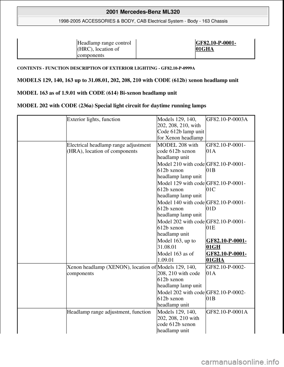
CONTENTS - FUNCTION DESCRIPTION OF EXTERIOR LIGHTING - GF82.10-P-0999A
MODELS 129, 140, 163 up to 31.08.01, 202, 208, 210 with CODE (612b) xenon headlamp unit
MODEL 163 as of 1.9.01 with CODE (614) Bi-xenon headlamp unit
MODEL 202 with CODE (236a) Special light circuit for daytime running lamps
Headlamp range control
(HRC), location of
components GF82.10-P-0001-
01GHA
Exterior lights, functionModels 129, 140,
202, 208, 210, with
Code 612b lamp unit
for Xenon headlampGF82.10-P-0003A
Electrical headlamp range adjustment
(HRA), location of componentsMODEL 208 with
code 612b xenon
headlamp unitGF82.10-P-0001-
01A
Model 210 with code
612b xenon
headlamp lamp unitGF82.10-P-0001-
01B
Model 129 with code
612b xenon
headlamp lamp unitGF82.10-P-0001-
01C
Model 140 with code
612b xenon
headlamp lamp unitGF82.10-P-0001-
01D
Model 202 with code
612b xenon
headlamp unitGF82.10-P-0001-
01E
Model 163, up to
31.08.01GF82.10-P-0001-
01GH
Model 163 as of
1.09.01GF82.10-P-0001-
01GHA
Xenon headlamp (XENON), location of
componentsModels 129, 140,
208, 210 with code
612b xenon
headlamp lamp unitGF82.10-P-0002-
01A
Model 202 with code
612b xenon
headlamp unitGF82.10-P-0002-
01B
Headlamp range adjustment, functionModels 129, 140,
202, 208, 210 with
code 612b xenon
headlamp unitGF82.10-P-0001A
2001 Mercedes-Benz ML320
1998-2005 ACCESSORIES & BODY, CAB Electrical System - Body - 163 Chassis
me
Saturday, October 02, 2010 3:30:04 PMPage 19 © 2006 Mitchell Repair Information Company, LLC.
Page 1515 of 4133
XENON HEADLAMPS, FUNCTION - GF82.10-P-2007-01GH
Function
The combustion chamber of the xenon lamp is filled with xenon and a mixture of metal halide salts. This
mixture is ignited by high voltage. The color of the light has a characteristic similar to daylight.
When the low beam lamps are switched on the xenon headlamp control module (E1 n1, E2n1) activates the
xenon headlamp control module and ignition module (E1n2, E2n2) via the control voltage within a few
milliseconds.
As a result of a high voltage surge (approx. 20 kV) of the ignition device, an arc forms between the electrodes,
and the xenon lamp is ignited.
When an arc of sufficient stability is detected, the control electronics of the xenon lamp control module (E1n1,
E2n1) switches over to power-limiting mode. The electric power is regulated to 35 W. A voltage converter
generates the voltage of approx. 85 V (~) necessary for the reliable function of the xenon lamp. For technical
reasons the xenon lamp has a timed startup characteristic. After switching on, 50 % of the luminosity is reached
within 1 to 2 seconds and full luminosity is reached after approx. 30 seconds.
Model 163, up to
31.08.01GF82.10-P-0001GH
Model 163 as of
1.09.01GF82.10-P-
0001GHA
Xenon headlamps, functionModel 163, up to
31.08.01GF82.10-P-2007-
01GH
Model 163 as of
1.09.01GF82.10-P-2007-
01GHA
Automatic driving light actuation,
functionModel 163 as of
01.09.01GF82.10-P-3003GH
Daytime running light control, functionModel 163 as of
01.09.01GF82.10-P-3005GH
Locator lighting, functionModel 163 as of
01.09.01GF80.20-P-2008GH
Headlamp cut-in, functionModel 163 as of
01.09.01GF80.20-P-2003GH
Daytime running lights, functionModel 202 with
Code 236a special
lamp circuit for
daytime running
lampsGF82.10-P-2002A
Contents - Function description of
exterior lighting,
location/task/design/functionModels 129, 140,
163, 202, 208, 210
with code 612b
xenon headlamp unitGF82.10-P-9999B
2001 Mercedes-Benz ML320
1998-2005 ACCESSORIES & BODY, CAB Electrical System - Body - 163 Chassis
me
Saturday, October 02, 2010 3:30:04 PMPage 20 © 2006 Mitchell Repair Information Company, LLC.