1997 MERCEDES-BENZ ML350 sensor
[x] Cancel search: sensorPage 3039 of 4133
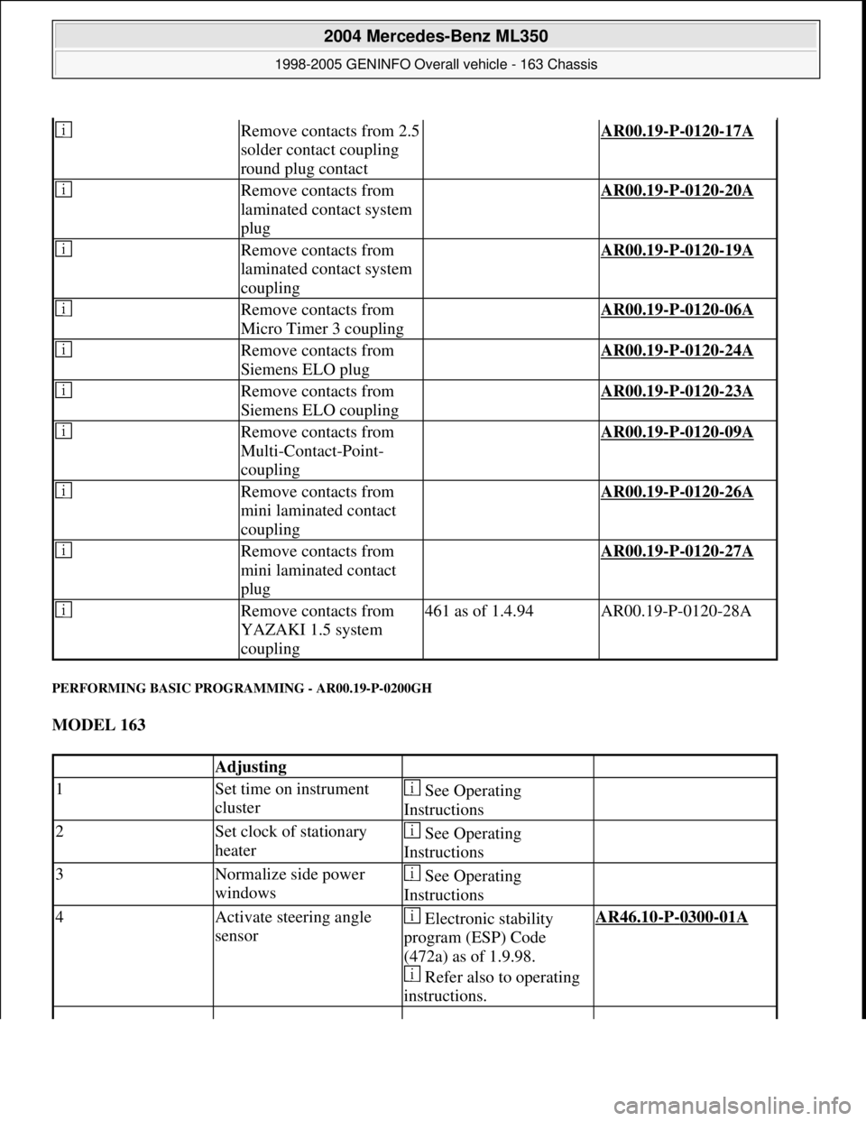
PERFORMING BASIC PROGRAMMING - AR00.19-P-0200GH
MODEL 163
Remove contacts from 2.5
solder contact coupling
round plug contact AR00.19-P-0120-17A
Remove contacts from
laminated contact system
plug AR00.19-P-0120-20A
Remove contacts from
laminated contact system
coupling AR00.19-P-0120-19A
Remove contacts from
Micro Timer 3 coupling AR00.19-P-0120-06A
Remove contacts from
Siemens ELO plug AR00.19-P-0120-24A
Remove contacts from
Siemens ELO coupling AR00.19-P-0120-23A
Remove contacts from
Multi-Contact-Point-
coupling AR00.19-P-0120-09A
Remove contacts from
mini laminated contact
coupling AR00.19-P-0120-26A
Remove contacts from
mini laminated contact
plug AR00.19-P-0120-27A
Remove contacts from
YAZAKI 1.5 system
coupling461 as of 1.4.94AR00.19-P-0120-28A
Adjusting
1Set time on instrument
cluster See Operating
Instructions
2Set clock of stationary
heater See Operating
Instructions
3Normalize side power
windows See Operating
Instructions
4Activate steering angle
sensor Electronic stability
program (ESP) Code
(472a) as of 1.9.98.
Refer also to operating
instructions.AR46.10-P-0300-01A
2004 Mercedes-Benz ML350
1998-2005 GENINFO Overall vehicle - 163 Chassis
me
Saturday, October 02, 2010 3:47:52 PMPage 394 © 2006 Mitchell Repair Information Company, LLC.
Page 3191 of 4133

Valve seal not okay :
#
3
Remove/install/replace valve seal.
AR05.30-P-3500B
Cause 6:
Remedy 6:
00 001 70
1.5 mm hole missing on individual right
cylinder head covers at connection to
crankcase ventilation.
1
Check cylinder head cover
Up to production 06/1999.
Crankcase ventilation out of order, engine can
sludge up and consume oil as a result
Cylinder head cover not okay:
#
2
Remove/install/replace cylinder head
cover.
ENGINE
112
Air cleaner positioned on engine
side.
ENGINE
113
Air cleaner positioned on engine
side.
AR01.20-P-5014BV
ENGINE
112
Air cleaner positioned on engine side
ENGINE
113
Air cleaner positioned on engine side
AR01.20-P-5014B
Cause 7:
Remedy 7:
00 001 70
Engine oil sludging due to excessively long
engine oil change intervals
Service information: Oil sludge
SI18.00-P-0010A
If the service interval according to
ASSYST is exceeded, the engine oil sludges
up sooner or later depending on the oil
quality, type of operation and operating time.
Engine consumes oil.
See Service Information.
1
Print out ASSYST printout.
2
Check oil change intervals
3
Inform vehicle owner.
4
Remove/install/replace piston rings.
AR03.10-P-7311BV
Disassemble and clean sludged engines
completely because dirty oil usually gets into
clean-oil side due to clogged oil filter.
Cause 8:
Remedy 8:
00 001 70
Piston rings sticky or have coke deposits from
engine oils (e.g. API-S in USA) in connection
with regionally poor fuel quality.
Always use engine oils according to
Specifications for Operating Fluids 229.3, do
not add special additives to engine oil and fuel
BB00.40-P-0229-03A
1
Remove/install/replace piston rings.
AR03.10-P-7311BV
Cause 9:
Remedy 9:
00 001 70
Piston ring wear due to excessive
contamination/dust (model 163) through air
intake system.
1
Remove/install/replace gaskets on air
intake line and distribution element of
partial load ventilation.
e.g. due to incorrect assembly after
workshop visit or embrittlement of gaskets
The distribution element with optimized
material will be available as of 11/ 2000 as a
standard feature.
2
Remove/install/replace intake module.
Exterior oil loss, e.g. due to cast iron
porosity on left side of crankcase in area of
engine support is not considered to be oil
consumption
In the event of a customer complaint
regarding the engine oil consumption, always
determine the oil consumption definitely
because the oil indicator lamp can come on
due to other causes (e.g. defective oil sensor).
Commercially available tools
(see Workshop Equipment Manual)
Number
Designation
Make (e. g.)
Order number
WH58.30-Z-1009-05A
Flexible inspection light
Scope of supply 1 (complete unit):
-glass fiber optical fiber
-light projector
-230 V, storage case
-operating instructions
-graphics protocol
Richard Wolf GmbH
Pforzheimerstr. 32
D-75438 Knittlingen
Karl Storz GmbH
Mittelstr. 8
D-78532 Tuttlingen
1.00565.00
80902
WH58.30-Z-1010-05A
Flexible inspection light
Scope of delivery 2 (for workshops which already have an approved
Wolf or Storz inspection light):
-storage case
-operating instructions
-pictures protocol
Richard Wolf GmbH
Pforzheimerstr. 32
D-75438 Knittlingen
Karl Storz GmbH
Mittelstr. 8
D-78532 Tuttlingen
7.05065.00
K03506AJ
Copyright DaimlerChrysler AG 20.05.2006 CD-Ausgabe G/10/04 . This WIS print-out will not be recorde
d by Modification services.
Page 2
Page 3216 of 4133
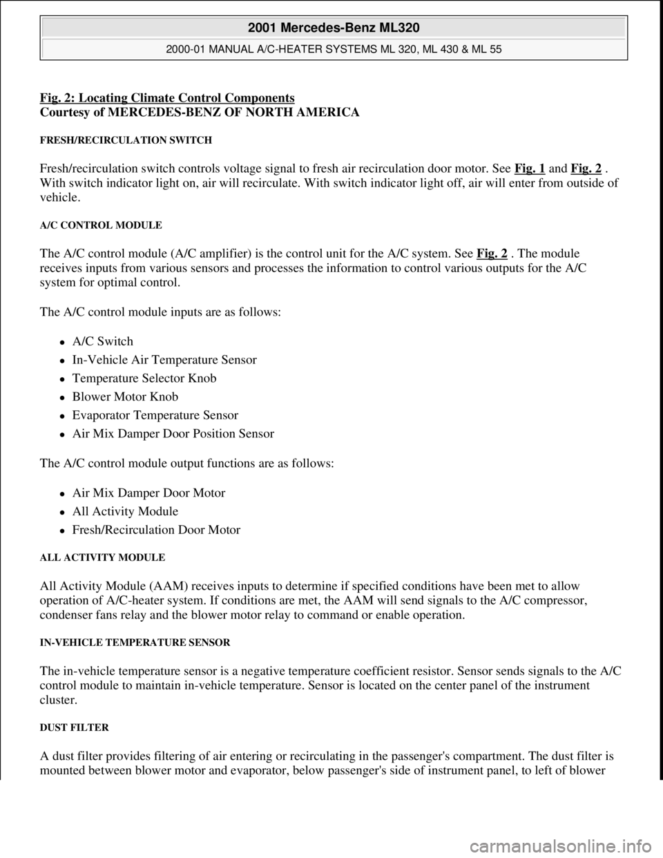
Fig. 2: Locating Climate Control Components
Courtesy of MERCEDES-BENZ OF NORTH AMERICA
FRESH/RECIRCULATION SWITCH
Fresh/recirculation switch controls voltage signal to fresh air recirculation door motor. See Fig. 1 and Fig. 2 .
With switch indicator light on, air will recirculate. With switch indicator light off, air will enter from outside of
vehicle.
A/C CONTROL MODULE
The A/C control module (A/C amplifier) is the control unit for the A/C system. See Fig. 2 . The module
receives inputs from various sensors and processes the information to control various outputs for the A/C
system for optimal control.
The A/C control module inputs are as follows:
A/C Switch
In-Vehicle Air Temperature Sensor
Temperature Selector Knob
Blower Motor Knob
Evaporator Temperature Sensor
Air Mix Damper Door Position Sensor
The A/C control module output functions are as follows:
Air Mix Damper Door Motor
All Activity Module
Fresh/Recirculation Door Motor
ALL ACTIVITY MODULE
All Activity Module (AAM) receives inputs to determine if specified conditions have been met to allow
operation of A/C-heater system. If conditions are met, the AAM will send signals to the A/C compressor,
condenser fans relay and the blower motor relay to command or enable operation.
IN-VEHICLE TEMPERATURE SENSOR
The in-vehicle temperature sensor is a negative temperature coefficient resistor. Sensor sends signals to the A/C
control module to maintain in-vehicle temperature. Sensor is located on the center panel of the instrument
cluster.
DUST FILTER
A dust filter provides filtering of air entering or recirculating in the passenger's compartment. The dust filter is
mounted between blower motor and evaporator, below passen
ger's side of instrument panel, to left of blower
2001 Mercedes-Benz ML320
2000-01 MANUAL A/C-HEATER SYSTEMS ML 320, ML 430 & ML 55
me
Saturday, October 02, 2010 3:25:10 PMPage 5 © 2006 Mitchell Repair Information Company, LLC.
Page 3218 of 4133
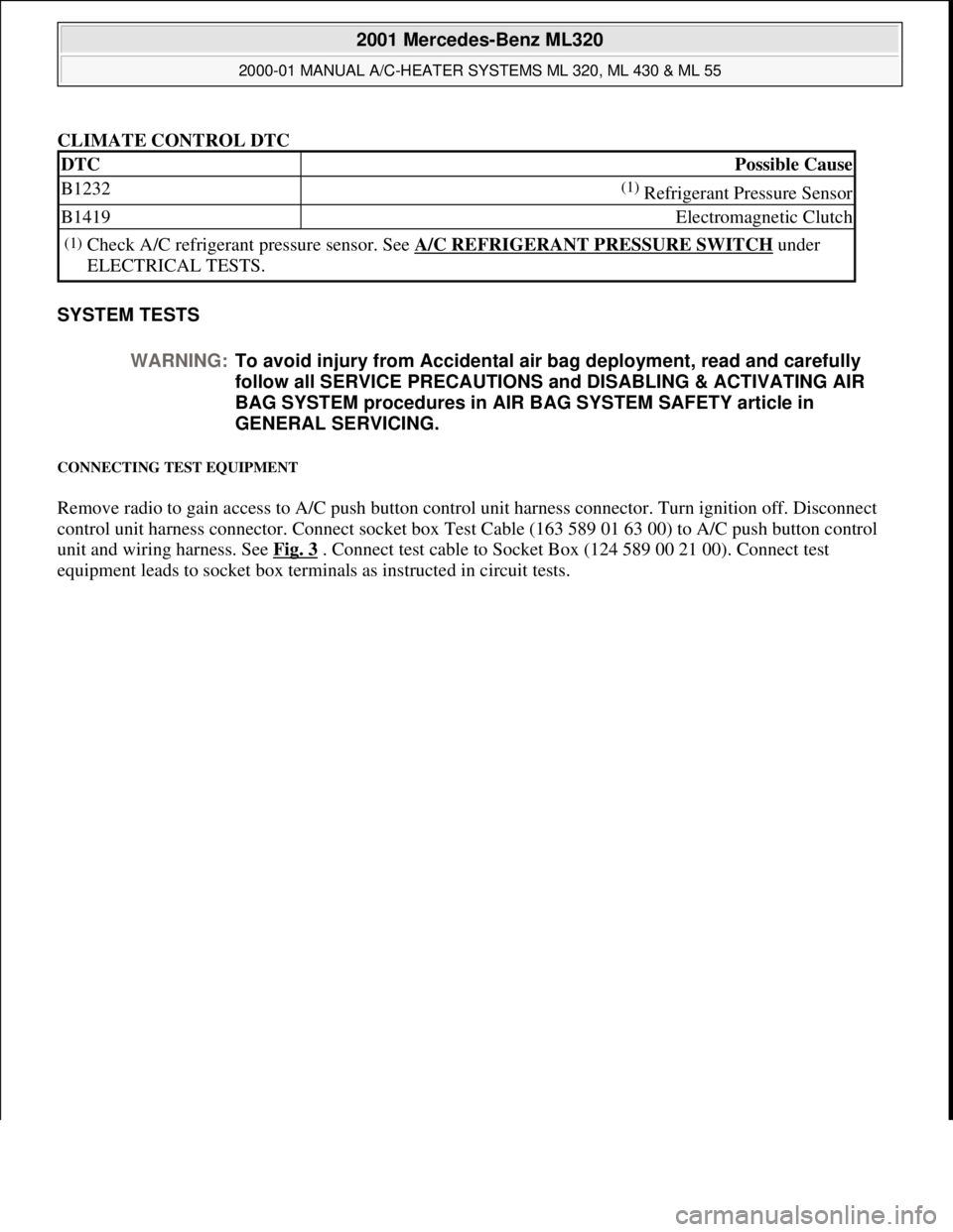
CLIMATE CONTROL DTC
SYSTEM TESTS
CONNECTING TEST EQUIPMENT
Remove radio to gain access to A/C push button control unit harness connector. Turn ignition off. Disconnect
control unit harness connector. Connect socket box Test Cable (163 589 01 63 00) to A/C push button control
unit and wiring harness. See Fig. 3
. Connect test cable to Socket Box (124 589 00 21 00). Connect test
equipment leads to socket box terminals as instructed in circuit tests.
DTCPossible Cause
B1232(1) Refrigerant Pressure Sensor
B1419Electromagnetic Clutch
(1)Check A/C refrigerant pressure sensor. See A/C REFRIGERANT PRESSURE SWITCH under
ELECTRICAL TESTS.
WARNING:To avoid injury from Accidental air bag deployment, read and carefully
follow all SERVICE PRECAUTIONS and DISABLING & ACTIVATING AIR
BAG SYSTEM procedures in AIR BAG SYSTEM SAFETY article in
GENERAL SERVICING.
2001 Mercedes-Benz ML320
2000-01 MANUAL A/C-HEATER SYSTEMS ML 320, ML 430 & ML 55
me
Saturday, October 02, 2010 3:25:10 PMPage 7 © 2006 Mitchell Repair Information Company, LLC.
Page 3220 of 4133
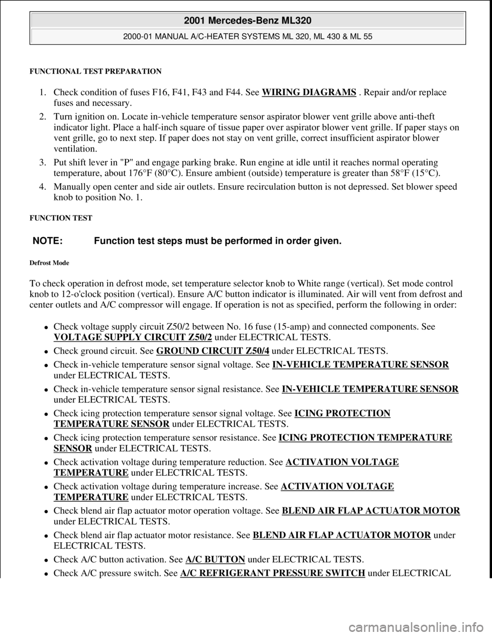
FUNCTIONAL TEST PREPARATION
1. Check condition of fuses F16, F41, F43 and F44. See WIRING DIAGRAMS . Repair and/or replace
fuses and necessary.
2. Turn ignition on. Locate in-vehicle temperature sensor aspirator blower vent grille above anti-theft
indicator light. Place a half-inch square of tissue paper over aspirator blower vent grille. If paper stays on
vent grille, go to next step. If paper does not stay on vent grille, correct insufficient aspirator blower
ventilation.
3. Put shift lever in "P" and engage parking brake. Run engine at idle until it reaches normal operating
temperature, about 176°F (80°C). Ensure ambient (outside) temperature is greater than 58°F (15°C).
4. Manually open center and side air outlets. Ensure recirculation button is not depressed. Set blower speed
knob to position No. 1.
FUNCTION TEST
Defrost Mode
To check operation in defrost mode, set temperature selector knob to White range (vertical). Set mode control
knob to 12-o'clock position (vertical). Ensure A/C button indicator is illuminated. Air will vent from defrost and
center outlets and A/C compressor will engage. If operation is not as specified, perform the following in order:
Check voltage supply circuit Z50/2 between No. 16 fuse (15-amp) and connected components. See
VOLTAGE SUPPLY CIRCUIT Z50/2
under ELECTRICAL TESTS.
Check ground circuit. See GROUND CIRCUIT Z50/4 under ELECTRICAL TESTS.
Check in-vehicle temperature sensor signal voltage. See IN-VEHICLE TEMPERATURE SENSOR
under ELECTRICAL TESTS.
Check in-vehicle temperature sensor signal resistance. See IN-VEHICLE TEMPERATURE SENSOR
under ELECTRICAL TESTS.
Check icing protection temperature sensor signal voltage. See ICING PROTECTION
TEMPERATURE SENSOR under ELECTRICAL TESTS.
Check icing protection temperature sensor resistance. See ICING PROTECTION TEMPERATURE
SENSOR under ELECTRICAL TESTS.
Check activation voltage during temperature reduction. See ACTIVATION VOLTAGE
TEMPERATURE under ELECTRICAL TESTS.
Check activation voltage during temperature increase. See ACTIVATION VOLTAGE
TEMPERATURE under ELECTRICAL TESTS.
Check blend air flap actuator motor operation voltage. See BLEND AIR FLAP ACTUATOR MOTOR
under ELECTRICAL TESTS.
Check blend air flap actuator motor resistance. See BLEND AIR FLAP ACTUATOR MOTOR under
ELECTRICAL TESTS.
Check A/C button activation. See A/C BUTTON under ELECTRICAL TESTS.
Check A/C pressure switch. See A/C REFRIGERANT PRESSURE SWITCH under ELECTRICAL NOTE: Function test steps must be performed in order given.
2001 Mercedes-Benz ML320
2000-01 MANUAL A/C-HEATER SYSTEMS ML 320, ML 430 & ML 55
me
Saturday, October 02, 2010 3:25:10 PMPage 9 © 2006 Mitchell Repair Information Company, LLC.
Page 3222 of 4133
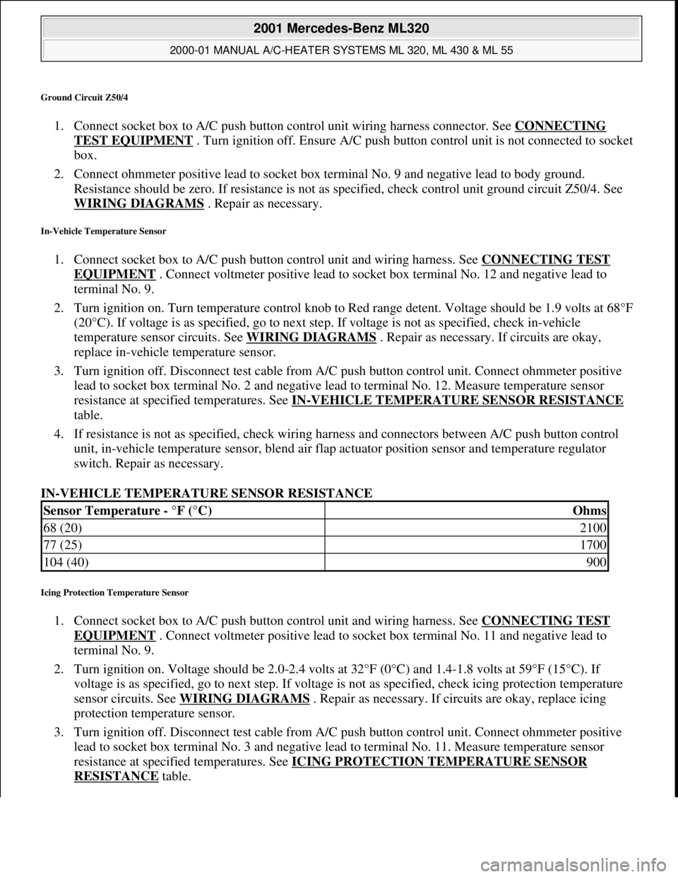
Ground Circuit Z50/4
1. Connect socket box to A/C push button control unit wiring harness connector. See CONNECTING
TEST EQUIPMENT . Turn ignition off. Ensure A/C push button control unit is not connected to socket
box.
2. Connect ohmmeter positive lead to socket box terminal No. 9 and negative lead to body ground.
Resistance should be zero. If resistance is not as specified, check control unit ground circuit Z50/4. See
WIRING DIAGRAMS
. Repair as necessary.
In-Vehicle Temperature Sensor
1. Connect socket box to A/C push button control unit and wiring harness. See CONNECTING TEST
EQUIPMENT . Connect voltmeter positive lead to socket box terminal No. 12 and negative lead to
terminal No. 9.
2. Turn ignition on. Turn temperature control knob to Red range detent. Voltage should be 1.9 volts at 68°F
(20°C). If voltage is as specified, go to next step. If voltage is not as specified, check in-vehicle
temperature sensor circuits. See WIRING DIAGRAMS
. Repair as necessary. If circuits are okay,
replace in-vehicle temperature sensor.
3. Turn ignition off. Disconnect test cable from A/C push button control unit. Connect ohmmeter positive
lead to socket box terminal No. 2 and negative lead to terminal No. 12. Measure temperature sensor
resistance at specified temperatures. See IN
-VEHICLE TEMPERATURE SENSOR RESISTANCE
table.
4. If resistance is not as specified, check wiring harness and connectors between A/C push button control
unit, in-vehicle temperature sensor, blend air flap actuator position sensor and temperature regulator
switch. Repair as necessary.
IN-VEHICLE TEMPERATURE SENSOR RESISTANCE
Icing Protection Temperature Sensor
1. Connect socket box to A/C push button control unit and wiring harness. See CONNECTING TEST
EQUIPMENT . Connect voltmeter positive lead to socket box terminal No. 11 and negative lead to
terminal No. 9.
2. Turn ignition on. Voltage should be 2.0-2.4 volts at 32°F (0°C) and 1.4-1.8 volts at 59°F (15°C). If
voltage is as specified, go to next step. If voltage is not as specified, check icing protection temperature
sensor circuits. See WIRING DIAGRAMS
. Repair as necessary. If circuits are okay, replace icing
protection temperature sensor.
3. Turn ignition off. Disconnect test cable from A/C push button control unit. Connect ohmmeter positive
lead to socket box terminal No. 3 and negative lead to terminal No. 11. Measure temperature sensor
resistance at specified temperatures. See ICING PROTECTION TEMPERATURE SENSOR
RESISTANCE table.
Sensor Temperature - °F (°C)Ohms
68 (20)2100
77 (25)1700
104 (40)900
2001 Mercedes-Benz ML320
2000-01 MANUAL A/C-HEATER SYSTEMS ML 320, ML 430 & ML 55
me
Saturday, October 02, 2010 3:25:10 PMPage 11 © 2006 Mitchell Repair Information Company, LLC.
Page 3223 of 4133
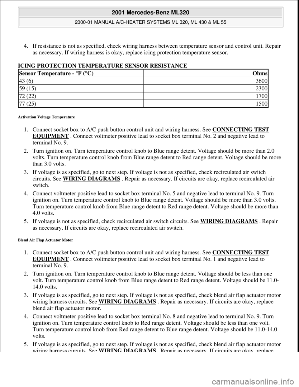
4. If resistance is not as specified, check wiring harness between temperature sensor and control unit. Repair
as necessary. If wiring harness is okay, replace icing protection temperature sensor.
ICING PROTECTION TEMPERATURE SENSOR RESISTANCE
Activation Voltage Temperature
1. Connect socket box to A/C push button control unit and wiring harness. See CONNECTING TEST
EQUIPMENT . Connect voltmeter positive lead to socket box terminal No. 2 and negative lead to
terminal No. 9.
2. Turn ignition on. Turn temperature control knob to Blue range detent. Voltage should be more than 2.0
volts. Turn temperature control knob from Blue range detent to Red range detent. Voltage should be more
than 3.0 volts.
3. If voltage is as specified, go to next step. If voltage is not as specified, check recirculated air switch
circuits. See WIRING DIAGRAMS
. Repair as necessary. If circuits are okay, replace recirculated air
switch.
4. Connect voltmeter positive lead to socket box terminal No. 5 and negative lead to terminal No. 9. Turn
ignition on. Turn temperature control knob to Blue range detent. Voltage should be more than 3.0 volts.
Turn temperature control knob from Blue range detent to Red range detent. Voltage should be more than
4.0 volts.
5. If voltage is not as specified, check recirculated air switch circuits. See WIRING DIAGRAMS
. Repair
as necessary. If circuits are okay, replace recirculated air switch.
Blend Air Flap Actuator Motor
1. Connect socket box to A/C push button control unit and wiring harness. See CONNECTING TEST
EQUIPMENT . Connect voltmeter positive lead to socket box terminal No. 1 and negative lead to
terminal No. 9.
2. Turn ignition on. Turn temperature control knob to Blue range detent. Voltage should be less than one
volt. Turn temperature control knob from Blue range detent to Red range detent. Voltage should be 11.0-
14.0 volts.
3. If voltage is as specified, go to next step. If voltage is not as specified, check blend air flap actuator motor
wiring harness circuits. See WIRING DIAGRAMS
. Repair as necessary. If circuits are okay, replace
blend air flap actuator motor.
4. Connect voltmeter positive lead to socket box terminal No. 8 and negative lead to terminal No. 9. Turn
ignition on. Turn temperature control knob to Red range detent. Voltage should be less than one volt.
Turn temperature control knob from Red range detent to Blue range detent. Voltage should be 11.0-14.0
volts.
5. If voltage is as specified, go to next step. If voltage is not as specified, check blend air flap actuator motor
wiring harness circuits. See WIRING DIAGRAMS
. Repair as necessary. If circuits are okay, replace
Sensor Temperature - °F (°C)Ohms
43 (6)3600
59 (15)2300
72 (22)1700
77 (25)1500
2001 Mercedes-Benz ML320
2000-01 MANUAL A/C-HEATER SYSTEMS ML 320, ML 430 & ML 55
me
Saturday, October 02, 2010 3:25:10 PMPage 12 © 2006 Mitchell Repair Information Company, LLC.
Page 3224 of 4133
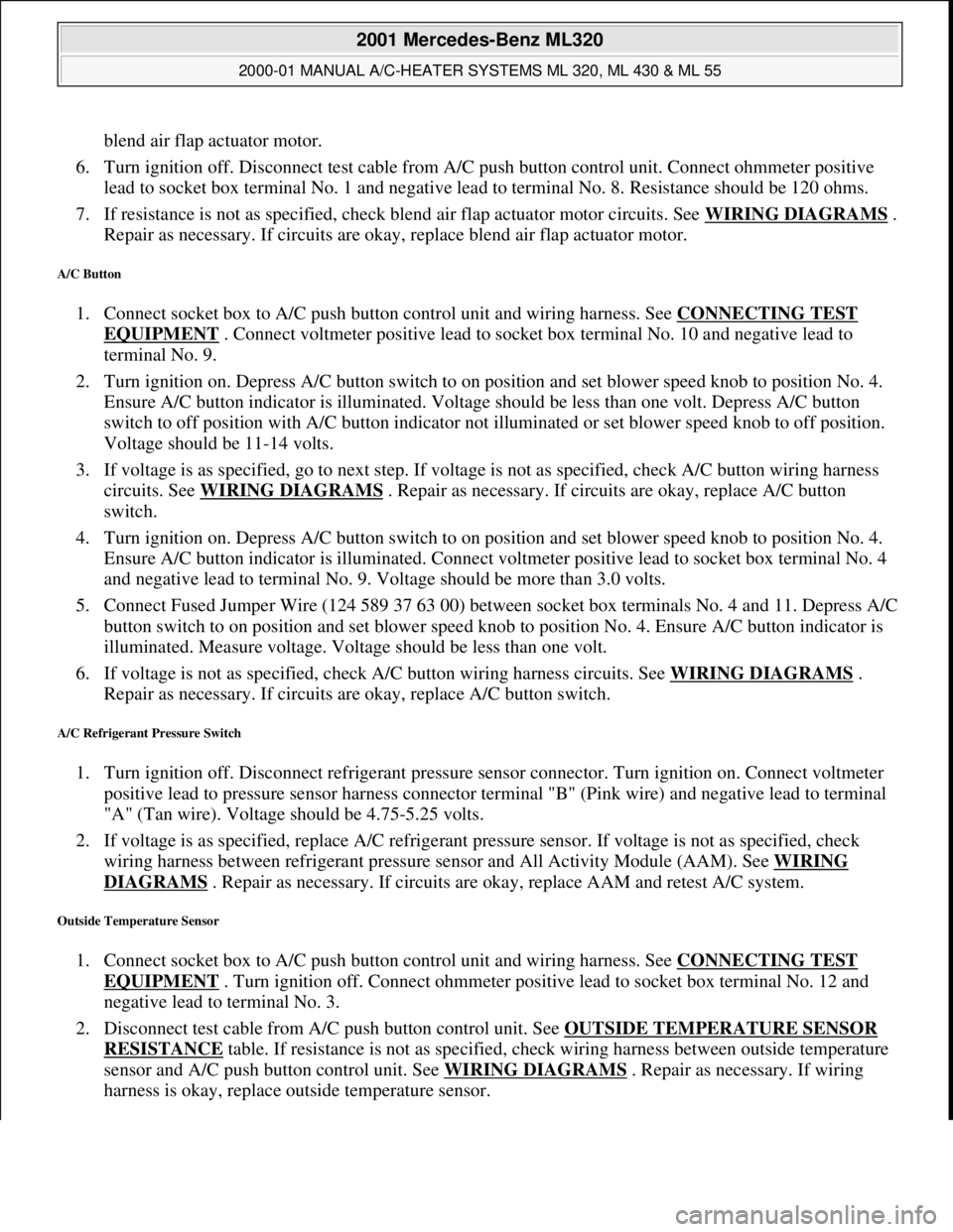
blend air flap actuator motor.
6. Turn ignition off. Disconnect test cable from A/C push button control unit. Connect ohmmeter positive
lead to socket box terminal No. 1 and negative lead to terminal No. 8. Resistance should be 120 ohms.
7. If resistance is not as specified, check blend air flap actuator motor circuits. See WIRING DIAGRAMS
.
Repair as necessary. If circuits are okay, replace blend air flap actuator motor.
A/C Button
1. Connect socket box to A/C push button control unit and wiring harness. See CONNECTING TEST
EQUIPMENT . Connect voltmeter positive lead to socket box terminal No. 10 and negative lead to
terminal No. 9.
2. Turn ignition on. Depress A/C button switch to on position and set blower speed knob to position No. 4.
Ensure A/C button indicator is illuminated. Voltage should be less than one volt. Depress A/C button
switch to off position with A/C button indicator not illuminated or set blower speed knob to off position.
Voltage should be 11-14 volts.
3. If voltage is as specified, go to next step. If voltage is not as specified, check A/C button wiring harness
circuits. See WIRING DIAGRAMS
. Repair as necessary. If circuits are okay, replace A/C button
switch.
4. Turn ignition on. Depress A/C button switch to on position and set blower speed knob to position No. 4.
Ensure A/C button indicator is illuminated. Connect voltmeter positive lead to socket box terminal No. 4
and negative lead to terminal No. 9. Voltage should be more than 3.0 volts.
5. Connect Fused Jumper Wire (124 589 37 63 00) between socket box terminals No. 4 and 11. Depress A/C
button switch to on position and set blower speed knob to position No. 4. Ensure A/C button indicator is
illuminated. Measure voltage. Voltage should be less than one volt.
6. If voltage is not as specified, check A/C button wiring harness circuits. See WIRING DIAGRAMS
.
Repair as necessary. If circuits are okay, replace A/C button switch.
A/C Refrigerant Pressure Switch
1. Turn ignition off. Disconnect refrigerant pressure sensor connector. Turn ignition on. Connect voltmeter
positive lead to pressure sensor harness connector terminal "B" (Pink wire) and negative lead to terminal
"A" (Tan wire). Voltage should be 4.75-5.25 volts.
2. If voltage is as specified, replace A/C refrigerant pressure sensor. If voltage is not as specified, check
wiring harness between refrigerant pressure sensor and All Activity Module (AAM). See WIRING
DIAGRAMS . Repair as necessary. If circuits are okay, replace AAM and retest A/C system.
Outside Temperature Sensor
1. Connect socket box to A/C push button control unit and wiring harness. See CONNECTING TEST
EQUIPMENT . Turn ignition off. Connect ohmmeter positive lead to socket box terminal No. 12 and
negative lead to terminal No. 3.
2. Disconnect test cable from A/C push button control unit. See OUTSIDE TEMPERATURE SENSOR
RESISTANCE table. If resistance is not as specified, check wiring harness between outside temperature
sensor and A/C push button control unit. See WIRING DIAGRAMS
. Repair as necessary. If wiring
harness is okay, replace outside temperature sensor.
2001 Mercedes-Benz ML320
2000-01 MANUAL A/C-HEATER SYSTEMS ML 320, ML 430 & ML 55
me
Saturday, October 02, 2010 3:25:10 PMPage 13 © 2006 Mitchell Repair Information Company, LLC.