1997 MERCEDES-BENZ ML350 sensor
[x] Cancel search: sensorPage 3225 of 4133
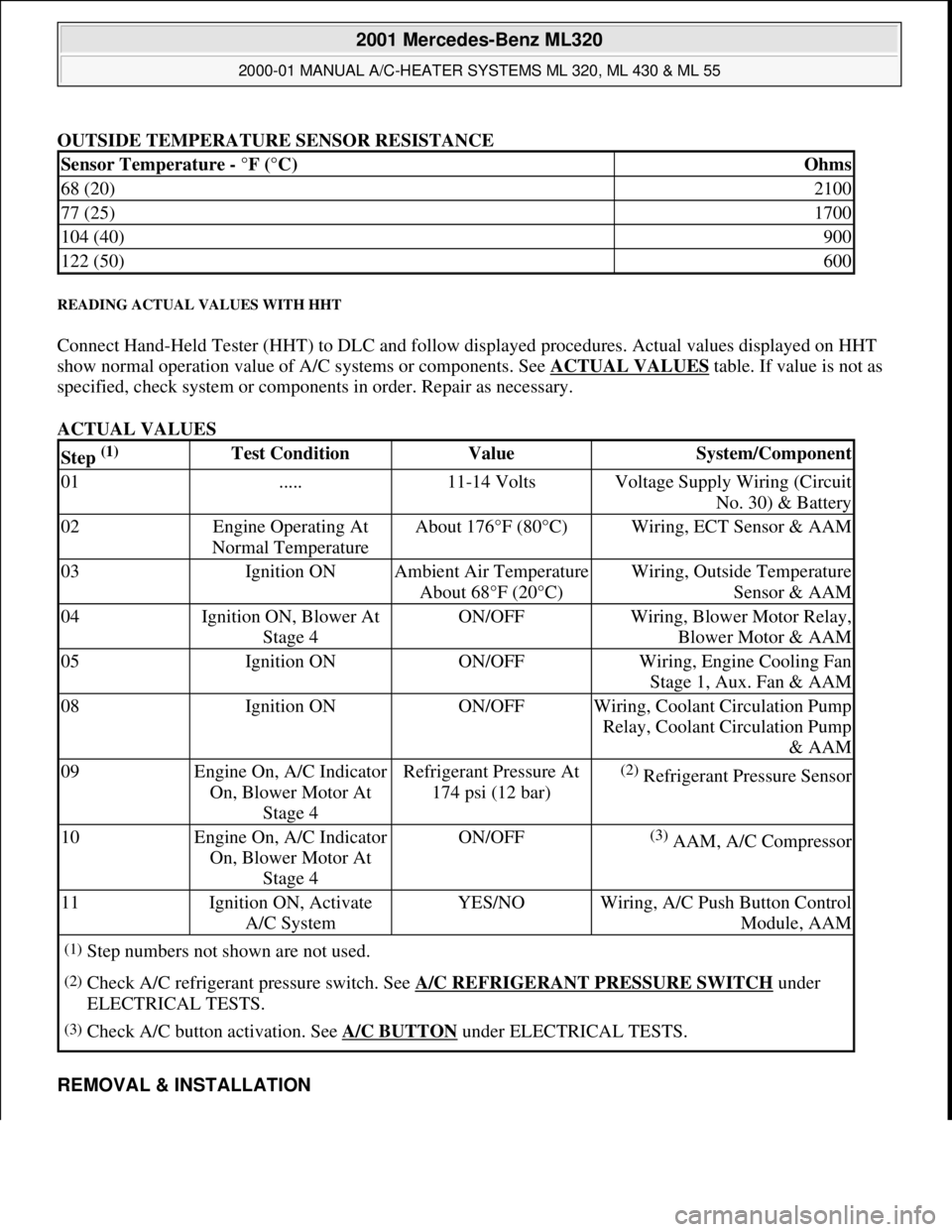
OUTSIDE TEMPERATURE SENSOR RESISTANCE
READING ACTUAL VALUES WITH HHT
Connect Hand-Held Tester (HHT) to DLC and follow displayed procedures. Actual values displayed on HHT
show normal operation value of A/C systems or components. See ACTUAL VALUES
table. If value is not as
specified, check system or components in order. Repair as necessary.
ACTUAL VALUES
REMOVAL & INSTALLATION
Sensor Temperature - °F (°C)Ohms
68 (20)2100
77 (25)1700
104 (40)900
122 (50)600
Step (1) Test ConditionValueSystem/Component
01.....11-14 VoltsVoltage Supply Wiring (Circuit
No. 30) & Battery
02Engine Operating At
Normal TemperatureAbout 176°F (80°C)Wiring, ECT Sensor & AAM
03Ignition ONAmbient Air Temperature
About 68°F (20°C)Wiring, Outside Temperature
Sensor & AAM
04Ignition ON, Blower At
Stage 4ON/OFFWiring, Blower Motor Relay,
Blower Motor & AAM
05Ignition ONON/OFFWiring, Engine Cooling Fan
Stage 1, Aux. Fan & AAM
08Ignition ONON/OFFWiring, Coolant Circulation Pump
Relay, Coolant Circulation Pump
& AAM
09Engine On, A/C Indicator
On, Blower Motor At
Stage 4Refrigerant Pressure At
174 psi (12 bar)(2) Refrigerant Pressure Sensor
10Engine On, A/C Indicator
On, Blower Motor At
Stage 4ON/OFF(3) AAM, A/C Compressor
11Ignition ON, Activate
A/C SystemYES/NOWiring, A/C Push Button Control
Module, AAM
(1)Step numbers not shown are not used.
(2)Check A/C refrigerant pressure switch. See A/C REFRIGERANT PRESSURE SWITCH under
ELECTRICAL TESTS.
(3)Check A/C button activation. See A/C BUTTON under ELECTRICAL TESTS.
2001 Mercedes-Benz ML320
2000-01 MANUAL A/C-HEATER SYSTEMS ML 320, ML 430 & ML 55
me
Saturday, October 02, 2010 3:25:10 PMPage 14 © 2006 Mitchell Repair Information Company, LLC.
Page 3226 of 4133
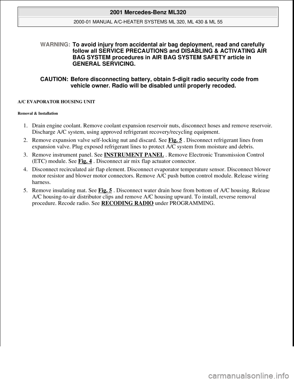
A/C EVAPORATOR HOUSING UNIT
Removal & Installation
1. Drain engine coolant. Remove coolant expansion reservoir nuts, disconnect hoses and remove reservoir.
Discharge A/C system, using approved refrigerant recovery/recycling equipment.
2. Remove expansion valve self-locking nut and discard. See Fig. 5
. Disconnect refrigerant lines from
expansion valve. Plug exposed refrigerant lines to protect A/C system from moisture and debris.
3. Remove instrument panel. See INSTRUMENT PANEL
. Remove Electronic Transmission Control
(ETC) module. See Fig. 4
. Disconnect air mix flap actuator connector.
4. Disconnect recirculated air flap element. Disconnect evaporator temperature sensor. Disconnect blower
motor resistor and blower motor connectors. Remove A/C push button control module. Release wiring
harness.
5. Remove insulating mat. See Fig. 5
. Disconnect water drain hose from bottom of A/C housing. Release
A/C housing-to-air distributor clips and remove A/C housing upward. To install, reverse removal
procedure. Recode radio. See RECODING RADIO
under PROGRAMMING. WARNING:To avoid injury from accidental air bag deployment, read and carefully
follow all SERVICE PRECAUTIONS and DISABLING & ACTIVATING AIR
BAG SYSTEM procedures in AIR BAG SYSTEM SAFETY article in
GENERAL SERVICING.
CAUTION: Before disconnecting battery, obtain 5-digit radio security code from
vehicle owner. Radio will be disabled until properly recoded.
2001 Mercedes-Benz ML320
2000-01 MANUAL A/C-HEATER SYSTEMS ML 320, ML 430 & ML 55
me
Saturday, October 02, 2010 3:25:10 PMPage 15 © 2006 Mitchell Repair Information Company, LLC.
Page 3232 of 4133
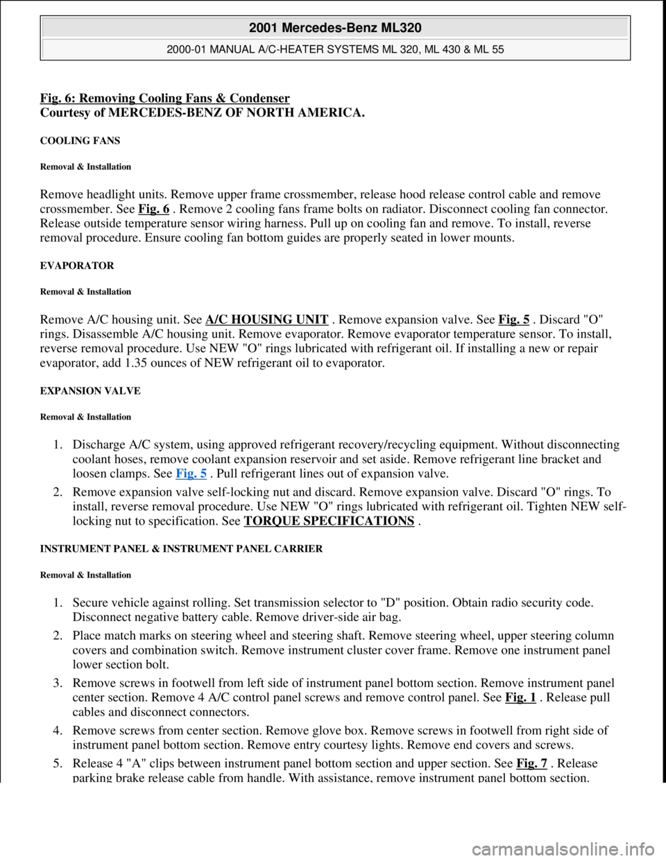
Fig. 6: Removing Cooling Fans & Condenser
Courtesy of MERCEDES-BENZ OF NORTH AMERICA.
COOLING FANS
Removal & Installation
Remove headlight units. Remove upper frame crossmember, release hood release control cable and remove
crossmember. See Fig. 6
. Remove 2 cooling fans frame bolts on radiator. Disconnect cooling fan connector.
Release outside temperature sensor wiring harness. Pull up on cooling fan and remove. To install, reverse
removal procedure. Ensure cooling fan bottom guides are properly seated in lower mounts.
EVAPORATOR
Removal & Installation
Remove A/C housing unit. See A/C HOUSING UNIT . Remove expansion valve. See Fig. 5 . Discard "O"
rings. Disassemble A/C housing unit. Remove evaporator. Remove evaporator temperature sensor. To install,
reverse removal procedure. Use NEW "O" rings lubricated with refrigerant oil. If installing a new or repair
evaporator, add 1.35 ounces of NEW refrigerant oil to evaporator.
EXPANSION VALVE
Removal & Installation
1. Discharge A/C system, using approved refrigerant recovery/recycling equipment. Without disconnecting
coolant hoses, remove coolant expansion reservoir and set aside. Remove refrigerant line bracket and
loosen clamps. See Fig. 5
. Pull refrigerant lines out of expansion valve.
2. Remove expansion valve self-locking nut and discard. Remove expansion valve. Discard "O" rings. To
install, reverse removal procedure. Use NEW "O" rings lubricated with refrigerant oil. Tighten NEW self-
locking nut to specification. See TORQUE SPECIFICATIONS
.
INSTRUMENT PANEL & INSTRUMENT PANEL CARRIER
Removal & Installation
1. Secure vehicle against rolling. Set transmission selector to "D" position. Obtain radio security code.
Disconnect negative battery cable. Remove driver-side air bag.
2. Place match marks on steering wheel and steering shaft. Remove steering wheel, upper steering column
covers and combination switch. Remove instrument cluster cover frame. Remove one instrument panel
lower section bolt.
3. Remove screws in footwell from left side of instrument panel bottom section. Remove instrument panel
center section. Remove 4 A/C control panel screws and remove control panel. See Fig. 1
. Release pull
cables and disconnect connectors.
4. Remove screws from center section. Remove glove box. Remove screws in footwell from right side of
instrument panel bottom section. Remove entry courtesy lights. Remove end covers and screws.
5. Release 4 "A" clips between instrument panel bottom section and upper section. See Fig. 7
. Release
parkin
g brake release cable from handle. With assistance, remove instrument panel bottom section.
2001 Mercedes-Benz ML320
2000-01 MANUAL A/C-HEATER SYSTEMS ML 320, ML 430 & ML 55
me
Saturday, October 02, 2010 3:25:10 PMPage 21 © 2006 Mitchell Repair Information Company, LLC.
Page 3302 of 4133
clockwise direction to the final indented position (max. cooling), the recirculation switch is bypassed and thus
the fresh air flaps closed, in order to achieve the max. interior cooling (with A/C ON).
TEMPERATURE SELECTOR WHEEL, FUNCTION - GF83.25-P-2102-01GI
Function
The desired in-car temperature is set by turning the temperature selector wheel on the AAC push-button control
module (N22).
The AAC push-button control module (N22) compares the desired temperature with the temperature in the
passenger compartment. The passenger compartment temperature is determined by the in-car temperature
sensor on the AAC push-button control module (N22) and the temperature sensor for the vent air at the center
nozzle, front and rear footwells.
Using the comparison between specified and actual values, the AAC push-button control module (N22)
determines the correct setting of the blending air flaps and actuates these. The selected temperature is reached
and maintained as quickly as possible, if warming or cooling of the interior is necessary.
TEMPERATURE SELECTOR WHEEL, LOCATION - GF83.25-P-2102-02GH
Heater depiction
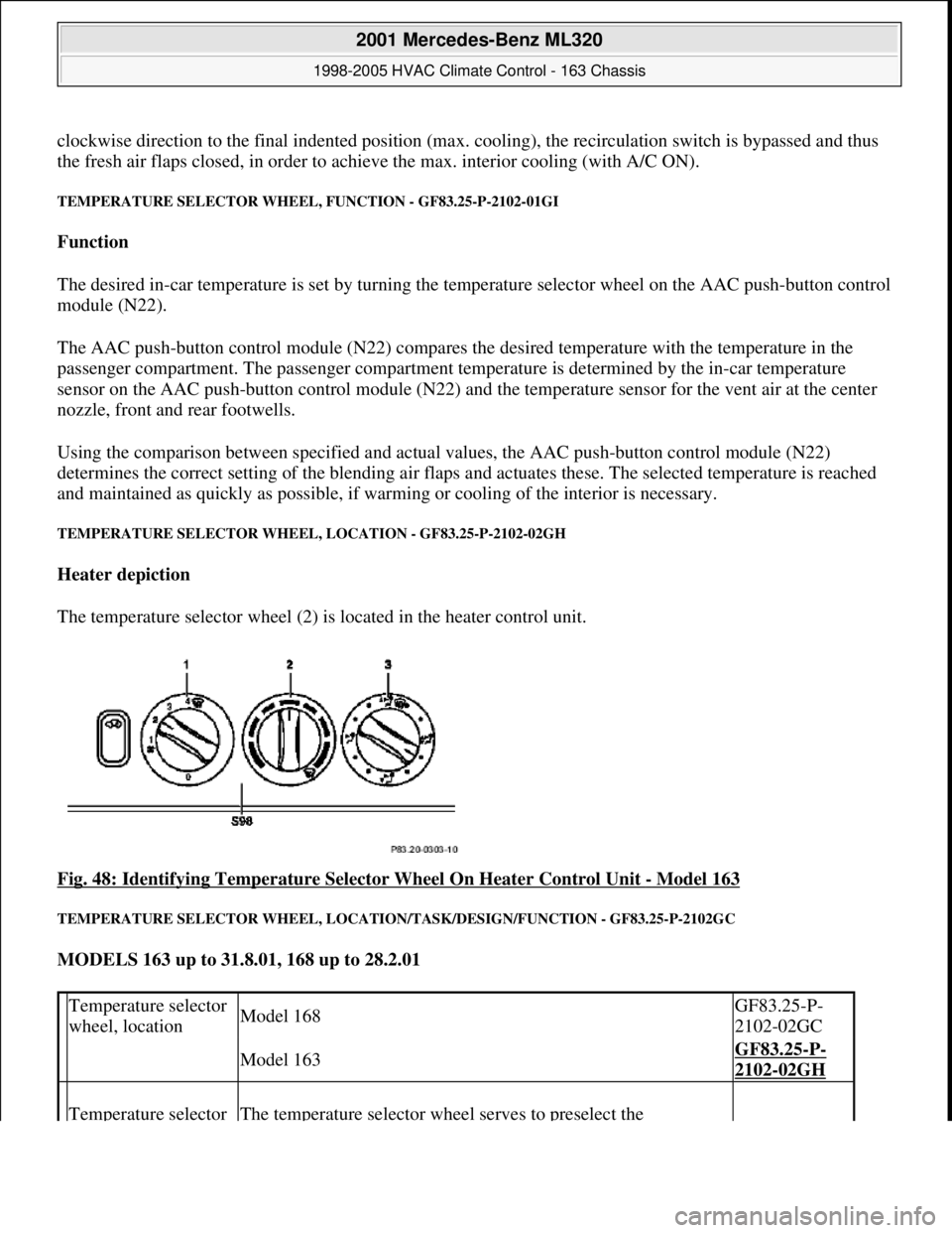
The temperature selector wheel (2) is located in the heater control unit.
Fig. 48: Identifying Temperature Selector Wheel On Heater Control Unit
- Model 163
TEMPERATURE SELECTOR WHEEL, LOCATION/TASK/DESIGN/FUNCTION - GF83.25-P-2102GC
MODELS 163 up to 31.8.01, 168 up to 28.2.01
Temperature selector
wheel, locationModel 168GF83.25-P-
2102-02GC
Model 163GF83.25-P-
2102-02GH
Temperature selector The temperature selector wheel serves to preselect the
2001 Mercedes-Benz ML320
1998-2005 HVAC Climate Control - 163 Chassis
me
Saturday, October 02, 2010 3:23:15 PMPage 58 © 2006 Mitchell Repair Information Company, LLC.
Page 3304 of 4133
After starting, the refrigerant compressor starts up. If cooling is not necessary, the refrigerant compressor's
output is lowered and switched off via the icing inhibitor.
The air conditioning is always ready for operation after the engine has been started, and operates according to
the so-called "reheat" principle. This means: The refrigerant compressor always operates at an ambient
temperature in excess of 1°C, therefore also cools cold incoming air. Following the cooling process, the dried
air is heated at the heat exchanger.
On the one hand, this effect serves the purpose of comfort, because cooling also simultaneously causes air
dehumidification which, in turn, is an important prerequisite for a pleasant interior climate. On the other hand,
the air is dried as a result of this cooling and heating, thereby preventing window fogging.
Pressing the AC button again ( ) (does not illuminate) switches off the cooling.
Heating mode
The in-car temperature sensor measures the air temperature in the interior of the vehicle.
The air conditioning control module electronics compares the in-car temperature with the desired temperature
which has been set at the temperature selector wheels.
The microprocessor adjusts the air conditioning electronics or keeps the relevant setting constant as required.
Heater operation with heater booster in vehicles with engine 612.963 as of 12/99
In vehicles equipped with direct-injection diesel engines, an electrical heater booster is additionally installed in
the evaporator housing downstream of the heat exchanger, in order to compensate any heater output deficit
which exists under certain operating conditions.
The 3 heating elements in the heater booster are supplied with current, whereupon they are heated and they start
to glow. As a result of the structural conditions, it is ensured that the drawn in fresh air flows directly past the
electric heater booster, and is therefore heated.
Cooling mode
The icing inhibitor measures the temperature at the evaporator air outlet, while the interior temperature sensor
determines the relevant in-car temperature.
The air conditioning control module electronics compares the various measured values with the desired
temperature which has been set at the temperature selector wheels.
The microprocessor adjusts the air conditioning or keeps the relevant setting constant as required.
In-car temperature sensor replaced by new typeas of 1.12.99BT83.57-P-0001-04GH
Ventilation, function GF83.10-P-2000GH
Heater circuit function GF83.20-P-2003GH
2001 Mercedes-Benz ML320
1998-2005 HVAC Climate Control - 163 Chassis
me
Saturday, October 02, 2010 3:23:15 PMPage 60 © 2006 Mitchell Repair Information Company, LLC.
Page 3311 of 4133
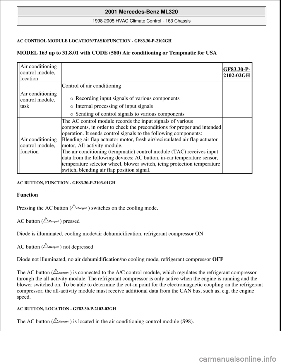
AC CONTROL MODULE LOCATION/TASK/FUNCTION - GF83.30-P-2102GH
MODEL 163 up to 31.8.01 with CODE (580) Air conditioning or Tempmatic for USA
AC BUTTON, FUNCTION - GF83.30-P-2103-01GH
Function
Pressing the AC button ( ) switches on the cooling mode.
AC button ( ) pressed
Diode is illuminated, cooling mode/air dehumidification, refrigerant compressor ON
AC button ( ) not depressed
Diode not illuminated, no air dehumidification/no cooling mode, refrigerant compressor OFF
The AC button ( ) is connected to the A/C control module, which regulates the refrigerant compressor
through the all-activity module. The refrigerant compressor is only active when the engine is running and the
blower switched on. To be able to determine the cut-in point for the electromagnetic coupling on the refrigerant
compressor, the all-activity module must receive additional data from the CAN bus, such as, e.g. the engine
speed.
AC BUTTON, LOCATION - GF83.30-P-2103-02GH
The AC button ( ) is located in the air conditioning control module (S98).
Air conditioning
control module,
location
GF83.30-P-
2102-02GH
Air conditioning
control module,
task
Control of air conditioning
Recording input signals of various components
Internal processing of input signals
Sending of control signals to various components
Air conditioning
control module,
function
The AC control module records the input signals of various
components, in order to check the preconditions for proper and intended
operation. It sends control signals to the following components:
Blending air flap actuator motor, fresh air/recirculated air flap actuator
motor, All-activity module.
The air conditioning (tempmatic) control module (TAC) receives input
data from the following devices: AC button, in-car temperature sensor,
temperature selector wheel, blower switch, icing protection temperature
switch, blending air flap position signal.
2001 Mercedes-Benz ML320
1998-2005 HVAC Climate Control - 163 Chassis
me
Saturday, October 02, 2010 3:23:15 PMPage 67 © 2006 Mitchell Repair Information Company, LLC.
Page 3323 of 4133
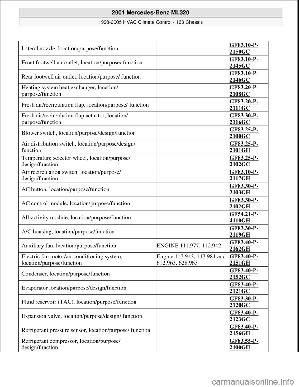
Lateral nozzle, location/purpose/function GF83.10-P-
2150GC
Front footwell air outlet, location/purpose/ function GF83.10-P-
2145GC
Rear footwell air outlet, location/purpose/ function GF83.10-P-
2146GC
Heating system heat exchanger, location/
purpose/function GF83.20-P-
2108GC
Fresh air/recirculation flap, location/purpose/ function GF83.20-P-
2111GC
Fresh air/recirculation flap actuator, location/
purpose/function GF83.30-P-
2116GC
Blower switch, location/purpose/design/function GF83.25-P-
2100GC
Air distribution switch, location/purpose/design/
function GF83.25-P-
2101GH
Temperature selector wheel, location/purpose/
design/function GF83.25-P-
2102GC
Air recirculation switch, location/purpose/
design/function GF83.10-P-
2117GH
AC button, location/purpose/function GF83.30-P-
2103GH
AC control module, location/purpose/function GF83.30-P-
2102GH
All-activity module, location/purpose/function GF54.21-P-
4110GH
A/C housing, location/purpose/function GF83.30-P-
2119GH
Auxiliary fan, location/purpose/functionENGINE 111.977, 112.942GF83.40-P-
2162GH
Electric fan motor/air conditioning system,
location/purpose/functionEngine 113.942, 113.981 and
612.963, 628.963GF83.40-P-
2151GH
Condenser, location/purpose/function GF83.40-P-
2152GC
Evaporator location/purpose/design/function GF83.40-P-
2121GC
Fluid reservoir (TAC), location/purpose/function GF83.30-P-
2120GC
Expansion valve, location/purpose/design/ function GF83.40-P-
2123GC
Refrigerant pressure sensor, location/purpose/ function GF83.40-P-
2156GH
Refrigerant compressor, location/purpose/
design/function GF83.55-P-
2100GH
2001 Mercedes-Benz ML320
1998-2005 HVAC Climate Control - 163 Chassis
me
Saturday, October 02, 2010 3:23:15 PMPage 79 © 2006 Mitchell Repair Information Company, LLC.
Page 3324 of 4133
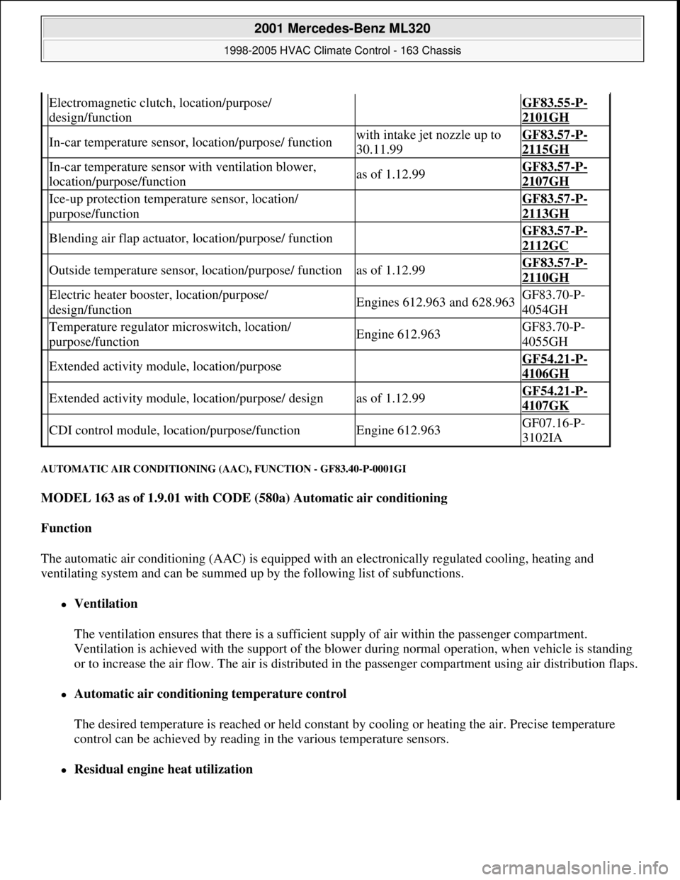
AUTOMATIC AIR CONDITIONING (AAC), FUNCTION - GF83.40-P-0001GI
MODEL 163 as of 1.9.01 with CODE (580a) Automatic air conditioning
Function
The automatic air conditioning (AAC) is equipped with an electronically regulated cooling, heating and
ventilating system and can be summed up by the following list of subfunctions.
Ventilation
The ventilation ensures that there is a sufficient supply of air within the passenger compartment.
Ventilation is achieved with the support of the blower during normal operation, when vehicle is standing
or to increase the air flow. The air is distributed in the passenger compartment using air distribution flaps.
Automatic air conditioning temperature control
The desired temperature is reached or held constant by cooling or heating the air. Precise temperature
control can be achieved by reading in the various temperature sensors.
Residual engine heat utilization
Electromagnetic clutch, location/purpose/
design/function GF83.55-P-
2101GH
In-car temperature sensor, location/purpose/ functionwith intake jet nozzle up to
30.11.99GF83.57-P-
2115GH
In-car temperature sensor with ventilation blower,
location/purpose/functionas of 1.12.99GF83.57-P-
2107GH
Ice-up protection temperature sensor, location/
purpose/function GF83.57-P-
2113GH
Blending air flap actuator, location/purpose/ function GF83.57-P-
2112GC
Outside temperature sensor, location/purpose/ functionas of 1.12.99GF83.57-P-
2110GH
Electric heater booster, location/purpose/
design/functionEngines 612.963 and 628.963GF83.70-P-
4054GH
Temperature regulator microswitch, location/
purpose/functionEngine 612.963GF83.70-P-
4055GH
Extended activity module, location/purpose GF54.21-P-
4106GH
Extended activity module, location/purpose/ designas of 1.12.99GF54.21-P-
4107GK
CDI control module, location/purpose/functionEngine 612.963GF07.16-P-
3102IA
2001 Mercedes-Benz ML320
1998-2005 HVAC Climate Control - 163 Chassis
me
Saturday, October 02, 2010 3:23:16 PMPage 80 © 2006 Mitchell Repair Information Company, LLC.