Page 2437 of 4133
Cylinder head bolts must not be retightened.
SLACKENING DIAGRAM FOR CYLINDER HEAD BOLTS - AR01.30-P-5800-09B
Fig. 76: Identifying Screwdriver Insert (000 589 03 10 00)
Fig. 77: Identifying Screwdr iver Insert (000 589 04 10 00)
Engine 112
Fig. 78: Identifying Loosening Se quence Of Cylinder Head Bolts
- Engine 112
1. Unscrew bolts (a, b).
Engine 113
2001 Mercedes-Benz ML320
1998-2005 ENGINE Complete engine - 163 Chassis
me
Saturday, October 02, 2010 3:17:56 PMPage 81 © 2006 Mitchell Repair Information Company, LLC.
Page 2438 of 4133
Fig. 79: Identifying Loosening Se quence Of Cylinder Head Bolts - Engine 113
2. Loosen cylinder head bolts (1 to 8 or 10) as per the numerical sequence and remove.
REMOVE/INSTALL CYLINDER HEAD - AR01.30-P-5800MV
ENGINE 112.942 in MODEL 163.154
ENGINE 112.970 in MODEL 163.157
ENGINE 113.942 in MODEL 163.172
ENGINE 113.981 in MODEL 163.174
ENGINE 113.965 in MODEL 163.175
Shown on model 163.154 with engine 112
2001 Mercedes-Benz ML320
1998-2005 ENGINE Complete engine - 163 Chassis
me
Saturday, October 02, 2010 3:17:57 PMPage 82 © 2006 Mitchell Repair Information Company, LLC.
Page 2439 of 4133
Fig. 80: Identifying Cylinder Head Remove/Install Components - Shown On Model 163.154 With Engine
112 (1 Of 3)
Fig. 81: Identifying Cylinder Head Remove/Install Components
- Shown On Model 163.154 With Engine
112 (2 Of 3)
2001 Mercedes-Benz ML320
1998-2005 ENGINE Complete engine - 163 Chassis
me
Saturday, October 02, 2010 3:17:57 PMPage 83 © 2006 Mitchell Repair Information Company, LLC.
Page 2440 of 4133
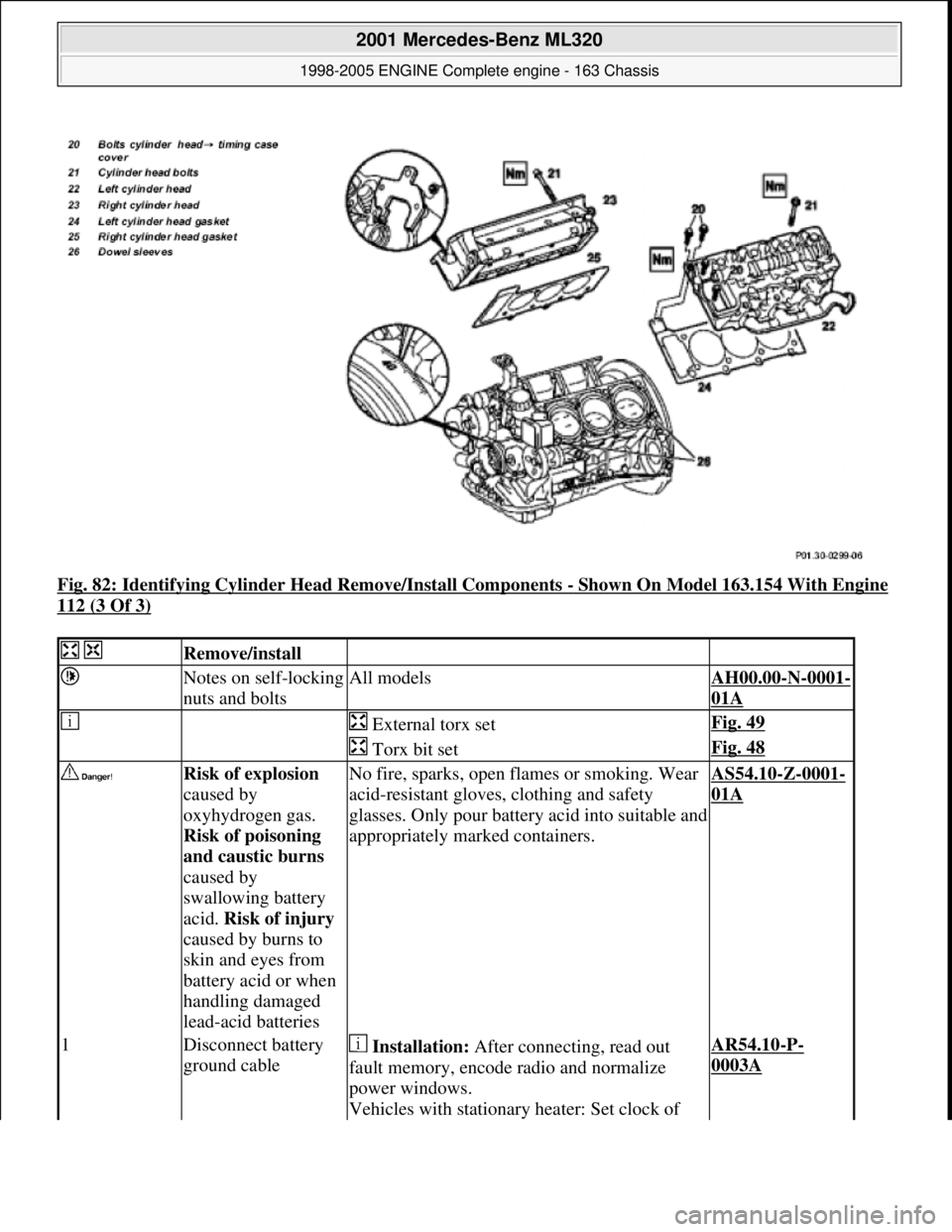
Fig. 82: Identifying Cylinder Head Remove/Install Components - Shown On Model 163.154 With Engine
112 (3 Of 3)
Remove/install
Notes on self-locking
nuts and boltsAll modelsAH00.00-N-0001-
01A
External torx setFig. 49
Torx bit setFig. 48
Risk of explosion
caused by
oxyhydrogen gas.
Risk of poisoning
and caustic burns
caused by
swallowing battery
acid. Risk of injury
caused by burns to
skin and eyes from
battery acid or when
handling damaged
lead-acid batteriesNo fire, sparks, open fl ames or smoking. Wear
acid-resistant gloves, clothing and safety
glasses. Only pour batter y acid into suitable and
appropriately marked containers.AS54.10-Z-0001-
01A
1Disconnect battery
ground cable Installation: After connecting, read out
fault memory, encode radio and normalize
power windows.
Vehicles with stationary heater: Set clock of AR54.10-P-
0003A
2001 Mercedes-Benz ML320
1998-2005 ENGINE Complete engine - 163 Chassis
me
Saturday, October 02, 2010 3:17:57 PMPage 84 © 2006 Mitchell Repair Information Company, LLC.
Page 2441 of 4133
stationary heater timer.
Notes on batteryAll modelsAH54.10-P-0001-
01A
Risk of death caused
by vehicle slipping
or toppling off of the
lifting platform.Align vehicle between the columns of the
lifting platform and pos ition the four support
plates below the lifti ng platform support points
specified by the vehicle manufacturer.AS00.00-Z-0010-
01A
2Place the vehicle on
lifting platform AR00.60-P-
1000GH
3.1Remove air guide (1) Only for engine 113.942.
Risk of injury to
skin and eyes caused
by scalding from
contact with hot
coolant spray. Risk
of poisoning from
swallowing coolant.Do not open cooling system unless coolant
temperature is below 90° C. Open cap slowly
and release the pressure. Do not pour coolant
into beverage containers.
Wear protective gloves, pr otective clothing and
safety glasses.AS20.00-Z-0001-
01A
4Drain coolant Detach coolant hose at bottom of radiator.AR20.00-P-
1142HA
5Remove engine trim
panel
6.1Remove viscous fan
(2) All except model 163.174 /175 with Engine
113.981 /965.
Right-hand thread!AR20.40-P-
5660C
7.1Remove fan shroud
(3) Only model 163.154 /157 /172. unscrew
screws (4) of bottom fan shroud.
7.2Remove electric fan Only models 163.174/ 175.AR20.40-P-
5000GH
8Attach guard plate
for radiator /
condenser
Guard plate for
radiator / condenserEngine 606 in model 124,
Engine 606.961 in model 140,
Engines 112, 113, 604, 605, 611.960 in model
202,
Engines 602.983, 612.966 in model 461,
Engine 628.962, 612.965, 606.964, 112.945,
113.962/982 in model 463,
Engines 111, 112, 611.962, 612.962 in model
203,
Engines 112, 113, 611.961, 612.961, 613.961
in model 210,
Engine 112 in model 170,
Engine 112 in model 220,
Engine 113 in models 211, 215, 220, WF58.50-P-0110-
01A
2001 Mercedes-Benz ML320
1998-2005 ENGINE Complete engine - 163 Chassis
me
Saturday, October 02, 2010 3:17:57 PMPage 85 © 2006 Mitchell Repair Information Company, LLC.
Page 2442 of 4133
Engine 112 in model 208,
Engine 112, 113, 612.963, 628.963 in model
163,
Engines 112.923/943, 113.961 in model 129,
Engines 137, 275 in models 215, 220,
Engines 613.960, 628.960 in model 220,
Engine 113.992 in model 230.474,
Engine 271 in MODELS 209, 203,
Engine 285.950 in models 240.078 /178,
Engine 612.967 in model 209.316,
Engine 648 in model 220 Engine 112.951 in
model
639.601/603 /605 /701 /703 /705 /801 /803 /805
Engine 646.983 /984 in model
639. /605 /701 /703/705/801 /803/805
Engine 646.982 in model
639.601 /603 /605 /701 /703 /705
9Remove air filter
housing (5).
10Remove air intake
pipe (6) with
resonance body (7) For this step separate connector of hot film
mass air flow sensor (HFM) and unscrew air
intake pipe at cylinder head cover.
The air intake pipe is attached to the rear of
the intake manifold with a plastic strap.
Do not damage the plastic strap.
Engines 112.942/970AR07.07-P-
1454A
Engines 113.942/965/981AR07.07-P-
1454MV
Risk of explosion
caused by fuel
igniting, risk of
poisoning caused by
inhaling and
swallowing fuel as
well as risk of
injury to eyes and
skin caused by
contact with fuel.No fire, sparks, open flames or smoking.
Pour fuels only into suitable and appropriately
marked containers.
Wear protective clothing when handling fuel.AS47.00-Z-0001-
01A
11Disconnect fuel line
at fuel rail Release fuel pressure at service valve.
Collect fuel!
Engine 112: ?
*BA07.52-P-
1001-01A
Engine 113: ?
2001 Mercedes-Benz ML320
1998-2005 ENGINE Complete engine - 163 Chassis
me
Saturday, October 02, 2010 3:17:57 PMPage 86 © 2006 Mitchell Repair Information Company, LLC.
Page 2443 of 4133
*BA07.52-P-
1001-01A
Pressure hoseFig. 52
12Remove right and
left ignition coils
(12) AR15.12-P-
2003A
13Remove right and
left cylinder head
covers (13) AR01.20-P-
5014B
14Remove intake
manifold (14) Installation: On vehicles with engine
damage, the intake manifold must be examined
for swarfs before assembling and any swarfs
present must be removed, in order to avoid
consequential damage.
The intake manifold system must not be
disassembled.
Remove intake manifold together with fuel
distributor.AR09.20-P-
1310A
15.1Remove camshaft
angle position sensor
(15) Only necessary if right cylinder head is
removed.AR15.10-P-
2000A
16Remove poly-V-belt
(8) Installation: Lock tensioning device with a
drift or pin (diameter 5 mm).
Models 163.154/157/172.AR13.22-P-
1202B
Models 163.174/175.AR13.22-P-
1202BA
17Detach coolant line
(16) at left cylinder
head 6 mm socket hexagon*WH58.30-Z-
1001-06A
7 mm socket hexagon*WH58.30-Z-
1002-06A
18.1Remove inner fender
(9) Only for engine 113.942 /965 /981.AR88.10-P-
1300GH
19.1Remove shield (10) Only for engine 113.942 /965 /981.
20.1Remove exhaust
bracket (11) Only for engine 113.942 /965 /981.
Support exhaust system.
21Detach exhaust
system at exhaust
manifold Installation: On vehicles with engine
damage check exhaust sy stem for chips before
assembly and remove any chips present to
prevent later damage
*BA14.10-P-
1002-01B
22Position crankshaft
to 40° after ignition The engine must not be turned back;
otherwise the timing chain can get jammed. AR05.10-P-
6858V
2001 Mercedes-Benz ML320
1998-2005 ENGINE Complete engine - 163 Chassis
me
Saturday, October 02, 2010 3:17:57 PMPage 87 © 2006 Mitchell Repair Information Company, LLC.
Page 2444 of 4133
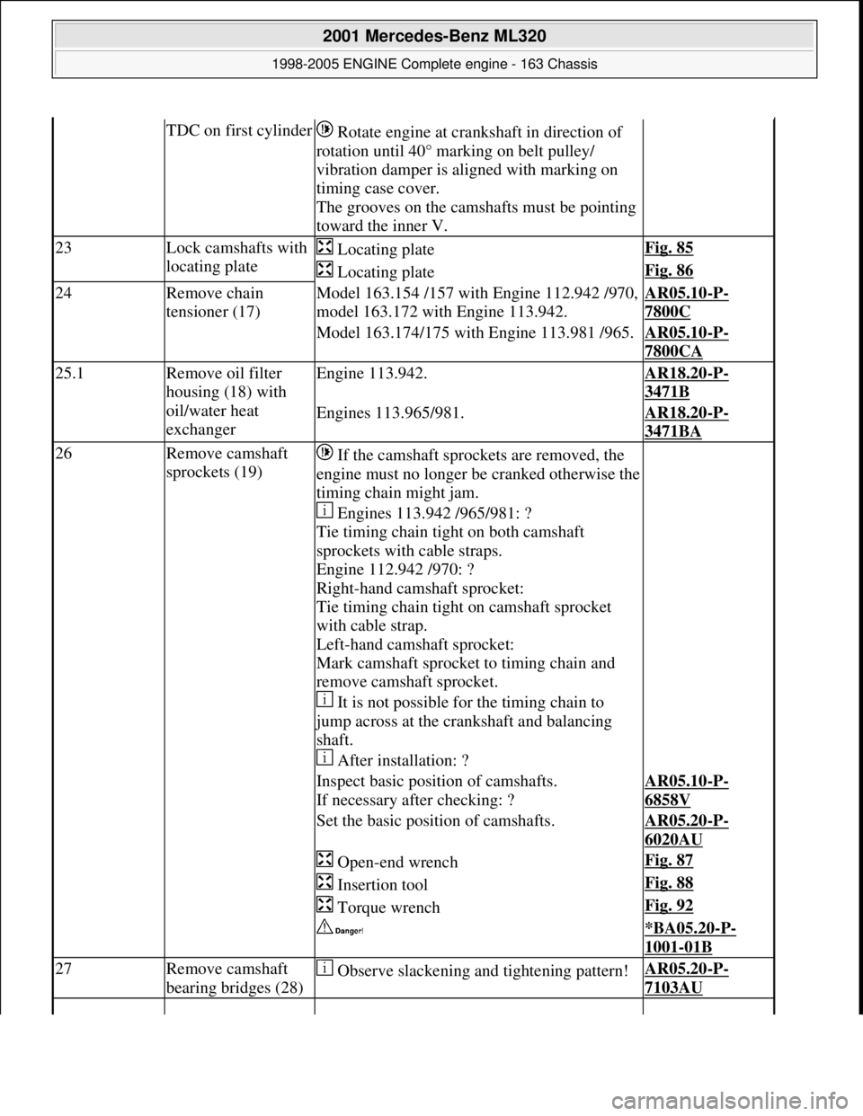
TDC on first cylinder Rotate engine at cra nkshaft in direction of
rotation until 40° marking on belt pulley/
vibration damper is al igned with marking on
timing case cover.
The grooves on the camshafts must be pointing
toward the inner V.
23Lock camshafts with
locating plate Locating plateFig. 85
Locating plateFig. 86
24Remove chain
tensioner (17)Model 163.154 /157 with Engine 112.942 /970,
model 163.172 with Engine 113.942.AR05.10-P-
7800C
Model 163.174/175 with Engine 113.981 /965.AR05.10-P-
7800CA
25.1Remove oil filter
housing (18) with
oil/water heat
exchangerEngine 113.942.AR18.20-P-
3471B
Engines 113.965/981.AR18.20-P-
3471BA
26Remove camshaft
sprockets (19) If the camshaft sprockets are removed, the
engine must no longer be cranked otherwise the
timing chain might jam.
Engines 113.942 /965/981: ?
Tie timing chain tight on both camshaft
sprockets with cable straps.
Engine 112.942 /970: ?
Right-hand camshaft sprocket:
Tie timing chain tight on camshaft sprocket
with cable strap.
Left-hand camshaft sprocket:
Mark camshaft sprocket to timing chain and
remove camshaft sprocket.
It is not possible for the timing chain to
jump across at the crankshaft and balancing
shaft.
After installation: ?
Inspect basic positi on of camshafts.
If necessary after checking: ?AR05.10-P-
6858V
Set the basic position of camshafts.AR05.20-P-
6020AU
Open-end wrenchFig. 87
Insertion toolFig. 88
Torque wrenchFig. 92
*BA05.20-P-
1001-01B
27Remove camshaft
bearing bridges (28) Observe slackening and tightening pattern!AR05.20-P-
7103AU
2001 Mercedes-Benz ML320
1998-2005 ENGINE Complete engine - 163 Chassis
me
Saturday, October 02, 2010 3:17:57 PMPage 88 © 2006 Mitchell Repair Information Company, LLC.