Page 2469 of 4133
Fig. 96: Identifying End Cover Remove/Install Components - Shown On Engine 112
Remove/install
1Remove flywheel/drive
plate AR03.30-P-8001C
2Remove the end cover (1). Pry off end cover (1)
carefully at both marked
points with a slanted
screwdriver (see magnified
section).
The crankshaft radial
sealing ring (3) must
always be replaced when
end cover (1) is removed.
*BA01.40-P-1004-01C
3Install a new rear
crankshaft radial seal (3) The rear crankshaft
radial sealing ring (3) must
only be removed once end
cover (1) has been
removed.
Installation:
Circumference and lip of
the crankshaft radial
sealing ring (3) as well as
the counter tread on the
2001 Mercedes-Benz ML320
1998-2005 ENGINE Complete engine - 163 Chassis
me
Saturday, October 02, 2010 3:17:57 PMPage 113 © 2006 Mitchell Repair Information Company, LLC.
Page 2470 of 4133
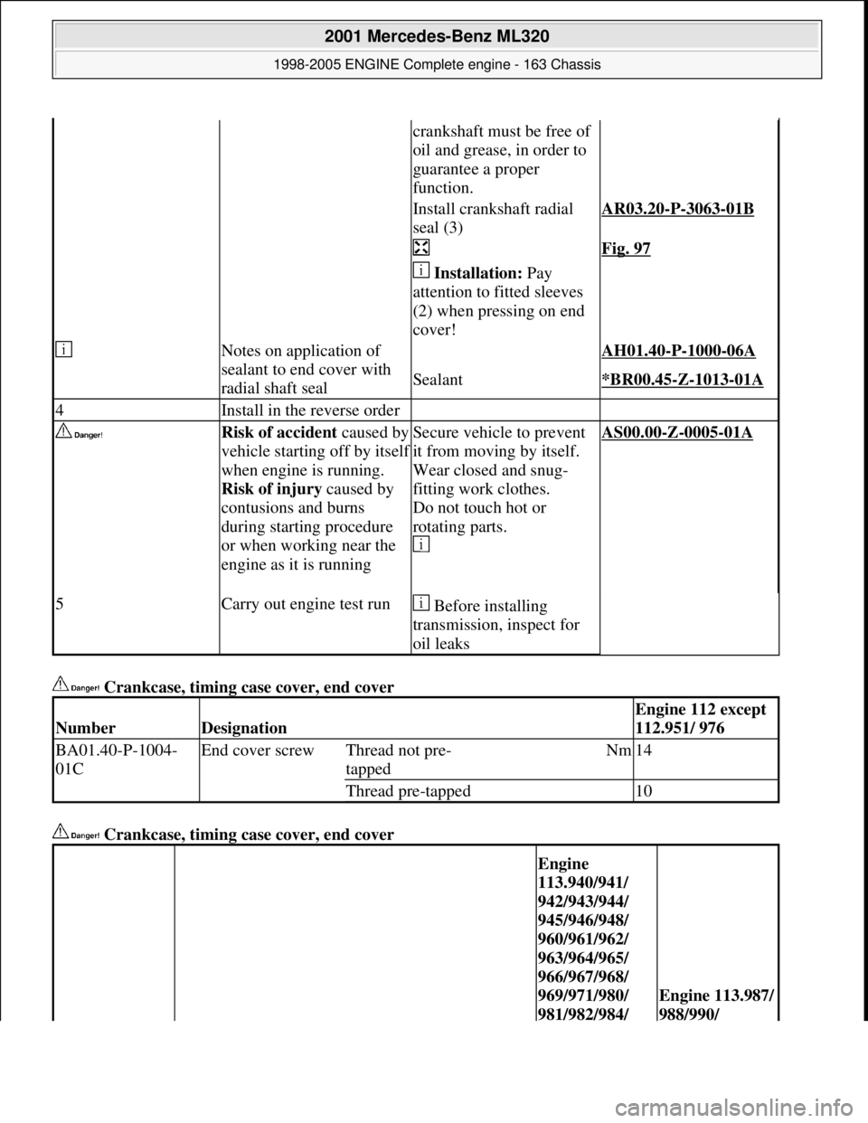
Crankcase, timing case cover, end cover
Crankcase, timing case cover, end cover
crankshaft must be free of
oil and grease, in order to
guarantee a proper
function.
Install crankshaft radial
seal (3)AR03.20-P-3063-01B
Fig. 97
Installation: Pay
attention to fitted sleeves
(2) when pressing on end
cover!
Notes on application of
sealant to end cover with
radial shaft seal AH01.40-P-1000-06A
Sealant*BR00.45-Z-1013-01A
4Install in the reverse order
Risk of accident caused by
vehicle starting off by itsel
f
when engine is running.
Risk of injury caused by
contusions and burns
during starting procedure
or when working near the
engine as it is running
Secure vehicle to prevent
it from moving by itself.
Wear closed and snug-
fitting work clothes.
Do not touch hot or
rotating parts.
AS00.00-Z-0005-01A
5Carry out engine test run Before installing
transmission, inspect for
oil leaks
NumberDesignation
Engine 112 except
112.951/ 976
BA01.40-P-1004-
01CEnd cover screwThread not pre-
tappedNm14
Thread pre-tapped10
Engine
113.940/941/
942/943/944/
945/946/948/
960/961/962/
963/964/965/
966/967/968/
969/971/980/
981/982/984/
Engine 113.987/
988/990/
2001 Mercedes-Benz ML320
1998-2005 ENGINE Complete engine - 163 Chassis
me
Saturday, October 02, 2010 3:17:57 PMPage 114 © 2006 Mitchell Repair Information Company, LLC.
Page 2471 of 4133
Fig. 97: Identifying Installa tion Tool (111 589 08 43 00)
Repair materials
CHAMFER CYLINDER BO RES - AR01.40-P-9201-01A
1. Chamfer off the burr which has accumulated on the cyli nder bores after drilling out using a suitable tool
(e.g. hand milling cutter).
Equalize the bottom edge of chamfer with a polishing stone.
Fig. 98: Removing Chamfer Burr From Cylinder Bore
NumberDesignation986/992/995991/993
BA01.40-P-
1004-01CEnd cover screwThread not
pretappedNm--
Thread pre-
tappedNm108
NumberDesignationOrder number
BR00.45-Z-1013-01ASealantA 003 989 98 20
2001 Mercedes-Benz ML320
1998-2005 ENGINE Complete engine - 163 Chassis
me
Saturday, October 02, 2010 3:17:57 PMPage 115 © 2006 Mitchell Repair Information Company, LLC.
Page 2472 of 4133
Fig. 99: Identifying Chamfer Angle Of Cylinder Bore
MEASURING, BORING AND HONING CYLINDER BORES - AR01.40-P-9201AA
ENGINES 112.910/911 /912 /920 /921 /922 /923 /940 / 941 /942 /943 /944 /945 /946 /947 /960 /961 /970
ENGINES 113.940 /941 /942 /943 /960 /961 /962 /963 /965 /968 /981 /982 /990 /991 /992 /993 /995
Fig. 100: Identifying Measurin g Points Of Cylinder Bore
1Clean cylinder bores
2Measure cylinder bore Measure cylinder bores
with an internal measuring
instrument at 3 measuring
points (1, 2, 3) in a
2001 Mercedes-Benz ML320
1998-2005 ENGINE Complete engine - 163 Chassis
me
Saturday, October 02, 2010 3:17:57 PMPage 116 © 2006 Mitchell Repair Information Company, LLC.
Page 2473 of 4133
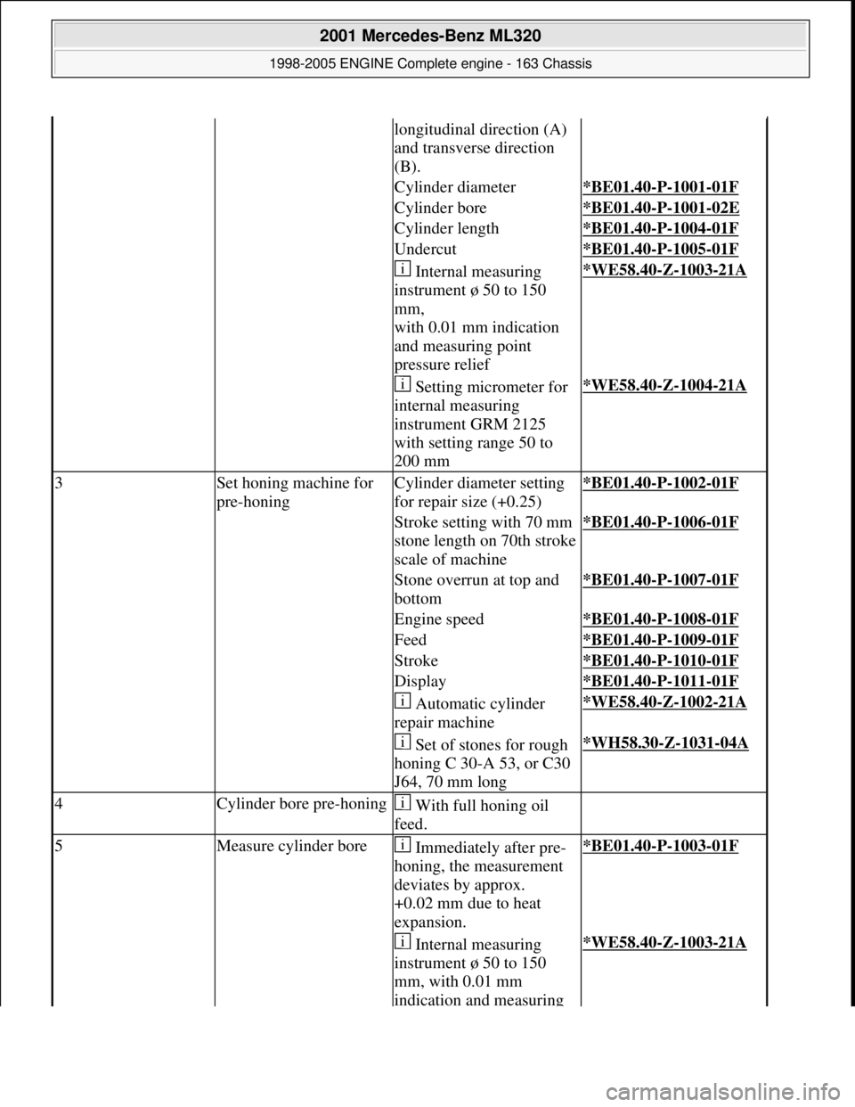
longitudinal direction (A)
and transverse direction
(B).
Cylinder diameter*BE01.40-P-1001-01F
Cylinder bore*BE01.40-P-1001-02E
Cylinder length*BE01.40-P-1004-01F
Undercut*BE01.40-P-1005-01F
Internal measuring
instrument ø 50 to 150
mm,
with 0.01 mm indication
and measuring point
pressure relief*WE58.40-Z-1003-21A
Setting micrometer for
internal measuring
instrument GRM 2125
with setting range 50 to
200 mm*WE58.40-Z-1004-21A
3Set honing machine for
pre-honingCylinder diameter setting
for repair size (+0.25)*BE01.40-P-1002-01F
Stroke setting with 70 mm
stone length on 70th stroke
scale of machine*BE01.40-P-1006-01F
Stone overrun at top and
bottom*BE01.40-P-1007-01F
Engine speed*BE01.40-P-1008-01F
Feed*BE01.40-P-1009-01F
Stroke*BE01.40-P-1010-01F
Display*BE01.40-P-1011-01F
Automatic cylinder
repair machine*WE58.40-Z-1002-21A
Set of stones for rough
honing C 30-A 53, or C30
J64, 70 mm long*WH58.30-Z-1031-04A
4Cylinder bore pre-honing With full honing oil
feed.
5Measure cylinder bore Immediately after pre-
honing, the measurement
deviates by approx.
+0.02 mm due to heat
expansion.*BE01.40-P-1003-01F
Internal measuring
instrument ø 50 to 150
mm, with 0.01 mm
indication and measuring *WE58.40-Z-1003-21A
2001 Mercedes-Benz ML320
1998-2005 ENGINE Complete engine - 163 Chassis
me
Saturday, October 02, 2010 3:17:57 PMPage 117 © 2006 Mitchell Repair Information Company, LLC.
Page 2474 of 4133
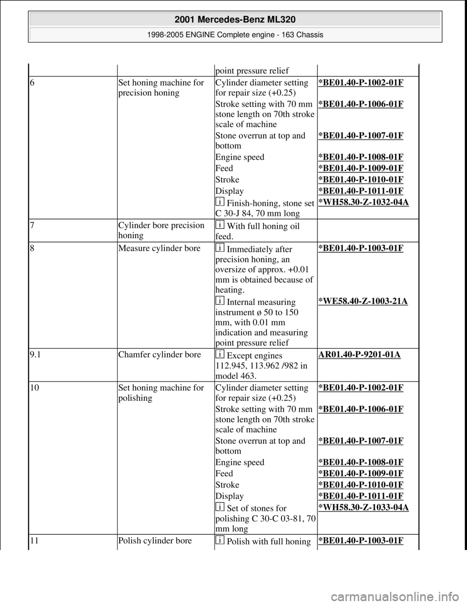
point pressure relief
6Set honing machine for
precision honingCylinder diameter setting
for repair size (+0.25)*BE01.40-P-1002-01F
Stroke setting with 70 mm
stone length on 70th stroke
scale of machine*BE01.40-P-1006-01F
Stone overrun at top and
bottom*BE01.40-P-1007-01F
Engine speed*BE01.40-P-1008-01F
Feed*BE01.40-P-1009-01F
Stroke*BE01.40-P-1010-01F
Display*BE01.40-P-1011-01F
Finish-honing, stone set
C 30-J 84, 70 mm long*WH58.30-Z-1032-04A
7Cylinder bore precision
honing With full honing oil
feed.
8Measure cylinder bore Immediately after
precision honing, an
oversize of approx. +0.01
mm is obtained because of
heating.*BE01.40-P-1003-01F
Internal measuring
instrument ø 50 to 150
mm, with 0.01 mm
indication and measuring
point pressure relief*WE58.40-Z-1003-21A
9.1Chamfer cylinder bore Except engines
112.945, 113.962 /982 in
model 463.AR01.40-P-9201-01A
10Set honing machine for
polishingCylinder diameter setting
for repair size (+0.25)*BE01.40-P-1002-01F
Stroke setting with 70 mm
stone length on 70th stroke
scale of machine*BE01.40-P-1006-01F
Stone overrun at top and
bottom*BE01.40-P-1007-01F
Engine speed*BE01.40-P-1008-01F
Feed*BE01.40-P-1009-01F
Stroke*BE01.40-P-1010-01F
Display*BE01.40-P-1011-01F
Set of stones for
polishing C 30-C 03-81, 70
mm long*WH58.30-Z-1033-04A
11Polish cylinder bore Polish with full honing *BE01.40-P-1003-01F
2001 Mercedes-Benz ML320
1998-2005 ENGINE Complete engine - 163 Chassis
me
Saturday, October 02, 2010 3:17:57 PMPage 118 © 2006 Mitchell Repair Information Company, LLC.
Page 2475 of 4133
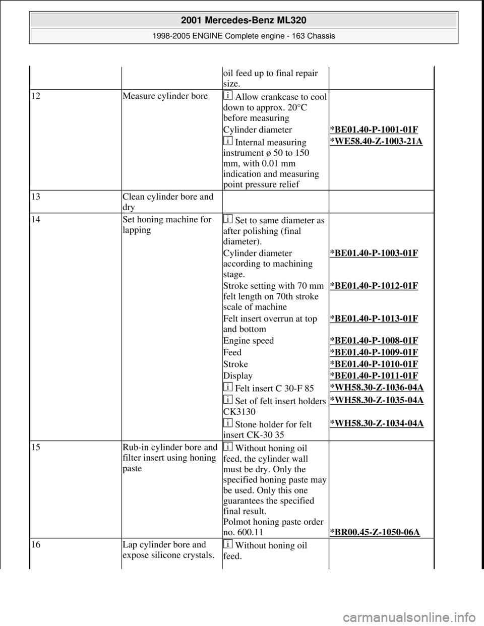
oil feed up to final repair
size.
12Measure cylinder boreAllow crankcase to cool
down to approx. 20°C
before measuring
Cylinder diameter*BE01.40-P-1001-01F
Internal measuring
instrument ø 50 to 150
mm, with 0.01 mm
indication and measuring
point pressure relief*WE58.40-Z-1003-21A
13Clean cylinder bore and
dry
14Set honing machine for
lapping Set to same diameter as
after polishing (final
diameter).
Cylinder diameter
according to machining
stage.*BE01.40-P-1003-01F
Stroke setting with 70 mm
felt length on 70th stroke
scale of machine*BE01.40-P-1012-01F
Felt insert overrun at top
and bottom*BE01.40-P-1013-01F
Engine speed*BE01.40-P-1008-01F
Feed*BE01.40-P-1009-01F
Stroke*BE01.40-P-1010-01F
Display*BE01.40-P-1011-01F
Felt insert C 30-F 85*WH58.30-Z-1036-04A
Set of felt insert holders
CK3130*WH58.30-Z-1035-04A
Stone holder for felt
insert CK-30 35*WH58.30-Z-1034-04A
15Rub-in cylinder bore and
filter insert using honing
paste Without honing oil
feed, the cylinder wall
must be dry. Only the
specified honing paste may
be used. Only this one
guarantees the specified
final result.
Polmot honing paste order
no. 600.11
*BR00.45-Z-1050-06A
16Lap cylinder bore and
expose silicone crystals. Without honing oil
feed.
2001 Mercedes-Benz ML320
1998-2005 ENGINE Complete engine - 163 Chassis
me
Saturday, October 02, 2010 3:17:57 PMPage 119 © 2006 Mitchell Repair Information Company, LLC.
Page 2476 of 4133
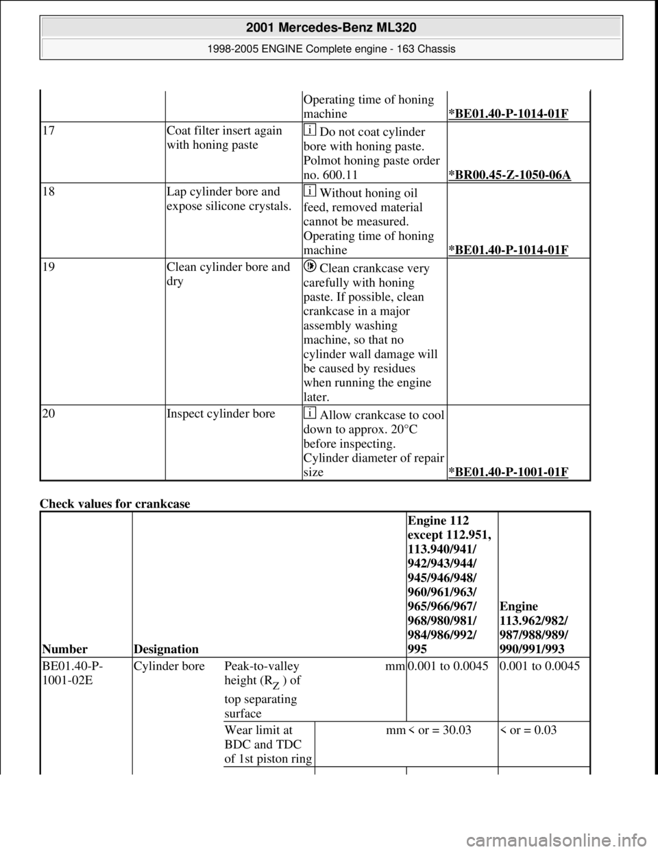
Check values for crankcase
Operating time of honing
machine
*BE01.40-P-1014-01F
17Coat filter insert again
with honing paste Do not coat cylinder
bore with honing paste.
Polmot honing paste order
no. 600.11
*BR00.45-Z-1050-06A
18Lap cylinder bore and
expose silicone crystals. Without honing oil
feed, removed material
cannot be measured.
Operating time of honing
machine
*BE01.40-P-1014-01F
19Clean cylinder bore and
dry Clean crankcase very
carefully with honing
paste. If possible, clean
crankcase in a major
assembly washing
machine, so that no
cylinder wall damage will
be caused by residues
when running the engine
later.
20Inspect cylinder boreAllow crankcase to cool
down to approx. 20°C
before inspecting.
Cylinder diameter of repair
size
*BE01.40-P-1001-01F
NumberDesignation
Engine 112
except 112.951,
113.940/941/
942/943/944/
945/946/948/
960/961/963/
965/966/967/
968/980/981/
984/986/992/
995
Engine
113.962/982/
987/988/989/
990/991/993
BE01.40-P-
1001-02E Cylinder borePeak-to-valley
height (R
Z ) of
top separating
surface
mm0.001 to 0.00450.001 to 0.0045
Wear limit at
BDC and TDC
of 1st piston ringmm< or = 30.03< or = 0.03
2001 Mercedes-Benz ML320
1998-2005 ENGINE Complete engine - 163 Chassis
me
Saturday, October 02, 2010 3:17:57 PMPage 120 © 2006 Mitchell Repair Information Company, LLC.