Page 2405 of 4133
Fig. 41: Identifying Compression Recorder (001 589 76 21 00)
Fig. 42: Identifying Adapter Cable (124 589 36 63 00)
Commercially available tools
REMOVE/INSTALL ENGINE - AR01.10-P-2400CA
ENGINE 112.942 in MODEL 163.154
ENGINE 112.970 in MODEL 163.157
ENGINE 113.942 in MODEL 163.172
ENGINE 113.981 in MODEL 163.174
ENGINE 113.965 in MODEL 163.175
Illustrated on model 112.942
NumberDesignation
WH58.30-Z-1036-13AHandheld tester (HHT)651 100 01 99
WH58.30-Z-1048-13ASTAR DIAGNOSIS diagnosis
system, Compact Passenger Car6511 1801 00
2001 Mercedes-Benz ML320
1998-2005 ENGINE Complete engine - 163 Chassis
me
Saturday, October 02, 2010 3:17:56 PMPage 49 © 2006 Mitchell Repair Information Company, LLC.
Page 2406 of 4133
Fig. 43: Identifying Engine Remove/Install Components - Illustrated On Model 112.942
Shown on engine 112.942
Fig. 44: Identifying Engine Remove/Install Component
- Shown On Engine 112.942
2001 Mercedes-Benz ML320
1998-2005 ENGINE Complete engine - 163 Chassis
me
Saturday, October 02, 2010 3:17:56 PMPage 50 © 2006 Mitchell Repair Information Company, LLC.
Page 2407 of 4133
Shown on engine 112.942
Fig. 45: Identifying Torque Converter
- Shown On Engine 112.942
Shown on engine 112.942
Fig. 46: Identifying Starter Ring Gear
- Shown On Engine 112.942
Shown on engine 112.942
2001 Mercedes-Benz ML320
1998-2005 ENGINE Complete engine - 163 Chassis
me
Saturday, October 02, 2010 3:17:56 PMPage 51 © 2006 Mitchell Repair Information Company, LLC.
Page 2408 of 4133
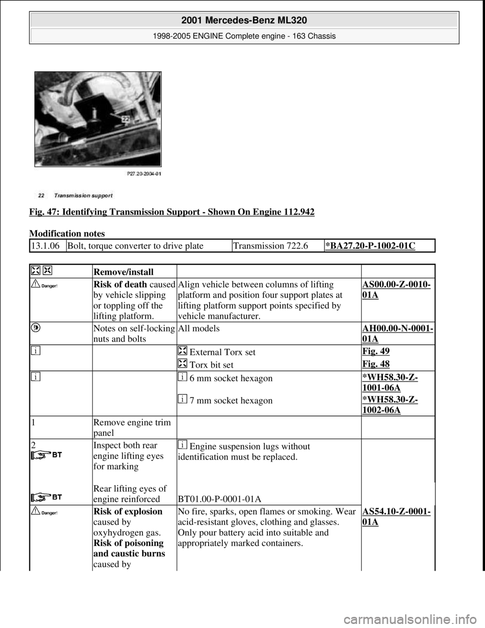
Fig. 47: Identifying Transmission Support - Shown On Engine 112.942
Modification notes
13.1.06Bolt, torque converter to drive plateTransmission 722.6*BA27.20-P-1002-01C
Remove/install
Risk of death caused
by vehicle slipping
or toppling off the
lifting platform.Align vehicle between columns of lifting
platform and position f our support plates at
lifting platform suppor t points specified by
vehicle manufacturer.AS00.00-Z-0010-
01A
Notes on self-locking
nuts and boltsAll modelsAH00.00-N-0001-
01A
External Torx setFig. 49
Torx bit setFig. 48
6 mm socket hexagon*WH58.30-Z-
1001-06A
7 mm socket hexagon*WH58.30-Z-
1002-06A
1Remove engine trim
panel
2
Inspect both rear
engine lifting eyes
for marking
Engine suspensi on lugs without
identification must be replaced.
Rear lifting eyes of
engine reinforced
BT01.00-P-0001-01A
Risk of explosion
caused by
oxyhydrogen gas.
Risk of poisoning
and caustic burns
caused by No fire, sparks, open fl ames or smoking. Wear
acid-resistant gloves, clothing and glasses.
Only pour battery acid into suitable and
appropriately marked containers.AS54.10-Z-0001-
01A
2001 Mercedes-Benz ML320
1998-2005 ENGINE Complete engine - 163 Chassis
me
Saturday, October 02, 2010 3:17:56 PMPage 52 © 2006 Mitchell Repair Information Company, LLC.
Page 2409 of 4133
swallowing battery
acid. Risk of injury
caused by burns to
skin and eyes from
battery acid or when
handling damaged
lead-acid batteries
3Disconnect battery
ground cable The battery is located in the right of the
engine compartment.AR54.10-P-
0003A
Notes on batteryAll modelsAH54.10-P-0001-
01A
Installation: After connecting, read out
fault memory, encode radio and normalize
power windows.Vehicles with
stationary heater:
adjust time
display on
stationary heater.
4.1Remove air guide
(23) Engine 113.942 only.
Risk of injury to
skin and eyes caused
by scalding from
contact with hot
coolant spray. Risk
of poisoning caused
by swallowing
coolant.Do not open cooling system unless coolant
temperature is below 90° C. Open cap slowly
and release the pressure. Do not pour coolant
into beverage containers.
Wear protective gloves, pr otective clothing and
safety glasses.AS20.00-Z-0001-
01A
5Drain coolant from
radiator Remove coolant pump line --> (16) from
coolant pump.AR20.00-P-
1142HA
6Drain and collect
engine oil *BA01.45-P-
1003-01B
*BF18.00-P-
1001-01H
7.1Remove viscous fan
(1)All except model 163.174 with engine 113.981
and 163.175 with engine 113.965.
Right-hand thread!AR20.40-P-
5660C
8.1Remove fan shroud
(2). Unscrew bolts at bottom of fan shroud
8.2Remove electric fan Only model 163.174 with engine 113.981
and 163.175 with engine 113.965.AR20.40-P-
5000GH
9Attach guard plate
for radiator /
condenser
Guard plate for
radiator / condenserEngine 606 in MODEL 124,
Engine 606.961 in MODEL 140,
Engine 112, 113, 604, 605, 611.960 in MODEL WF58.50-P-0110-
01A
2001 Mercedes-Benz ML320
1998-2005 ENGINE Complete engine - 163 Chassis
me
Saturday, October 02, 2010 3:17:56 PMPage 53 © 2006 Mitchell Repair Information Company, LLC.
Page 2410 of 4133
202,
Engine 602.983, 612.966 in MODEL 461,
Engine 628.962, 612.965, 606.964, 112.945,
113.962 /982 in MODEL 463,
Engine 111, 112, 611.962, 612.962 in model
203,
Engine 112, 113, 611.961, 612.961, 613.961 in
MODEL 210,
Engine 112 in model 170,
Engine 112 in MODEL 220,
Engine 113 in MODEL 211, 215,220,
Engine 112 in MODEL 208,
Engine 112, 113, 612.963, 628.963 in MODEL
163,
Engine 112.923/943, 113.961 in MODEL 129,
Engine 137, 275 in MODEL 215, 220,
Engine 613.960, 628.960 in MODEL 220,
Engine 113.992 in model 230.474,
Engine 271 in model 209, 203,
Engine 285.950 in model 240.078 /178,
Engine 612.967 in model 209.316,
Engine 648 in model 220
Engine 112.951 in model
639.601/603 /605 /701 /703 /705 /801 /803 /805
Engine 646.983 /984 in model
639. /605 /701 /703/705/801 /803/805
Engine 646.982 in model
639.601 /603 /605 /701 /703 /705
10Remove expansion
reservoir (13)
11Remove air filter
housing (7).
12Remove resonance
tube (8) and
resonance unit (9) Separate plug connection of hot film mass
air flow sensor (HFM) for this step and unbolt
resonance pipe at cy linder head cover.
The resonance pipe is attached at rear at
intake manifold with a plastic plate.
Do not damage plastic strap.
Engine 112.942/970.AR07.07-P-
1454A
Engine 113.942/965/981.AR07.07-P-
1454MV
13Remove coolant
pump line(15)from
coolant pump.
14Remove thermostat
2001 Mercedes-Benz ML320
1998-2005 ENGINE Complete engine - 163 Chassis
me
Saturday, October 02, 2010 3:17:56 PMPage 54 © 2006 Mitchell Repair Information Company, LLC.
Page 2411 of 4133
housing coolant line
--> (17) from
thermostat housing
15.1Remove radiator Only engine 113.942 /965 /981.AR20.20-P-
3865HC
16Remove brake
pressure regulator
vacuum line (5) from
brake pressure
regulator at rear of
intake manifold
17Extract power
steering pump (19)
oil Hand pumpFig. 50
18Detach return flow
line and pressure line
of power steering
pump (19) Seal connections!
Set of plugsFig. 51
*BA46.30-P-
1002-01A
*BA46.30-P-
1003-01A
19Remove regeneration
vacuum line (6) from
intake pipe
Risk of explosion
caused by ignition of
flammable products,
risk of poisoning
caused by inhaling
fuel vapors or
swallowing fuel as
well as risk of
injury to skin and
eyes exposed to fuel.No fire, sparks, ope n flames or smoking.AS47.00-Z-0001-
01A
Pour fuels only into suitable and appropriately
marked containers.
Wear protective clothing when handling fuel.
20Disconnect fuel line
(4) Release fuel pressure through service valve!
Collect fuel.
M112: ?
*BA07.52-P-
1001-01A
M113: ?
*BA07.52-P-
1001-01A
Pressure hoseFig. 52
21Detach coolant line
(14)
2001 Mercedes-Benz ML320
1998-2005 ENGINE Complete engine - 163 Chassis
me
Saturday, October 02, 2010 3:17:56 PMPage 55 © 2006 Mitchell Repair Information Company, LLC.
Page 2412 of 4133
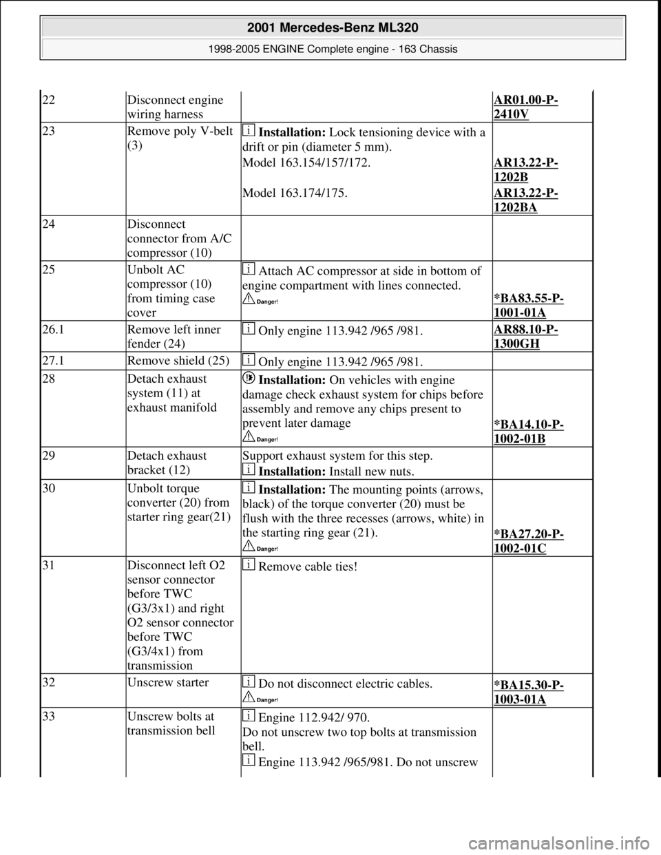
22Disconnect engine
wiring harness AR01.00-P-
2410V
23Remove poly V-belt
(3) Installation: Lock tensioning device with a
drift or pin (diameter 5 mm).
Model 163.154/157/172.AR13.22-P-
1202B
Model 163.174/175.AR13.22-P-
1202BA
24Disconnect
connector from A/C
compressor (10)
25Unbolt AC
compressor (10)
from timing case
cover Attach AC compressor at side in bottom of
engine compartment with lines connected.
*BA83.55-P-
1001-01A
26.1Remove left inner
fender (24) Only engine 113.942 /965 /981.AR88.10-P-
1300GH
27.1Remove shield (25) Only engine 113.942 /965 /981.
28Detach exhaust
system (11) at
exhaust manifold Installation: On vehicles with engine
damage check exhaust sy stem for chips before
assembly and remove any chips present to
prevent later damage
*BA14.10-P-
1002-01B
29Detach exhaust
bracket (12)Support exhaust system for this step.
Installation: Install new nuts.
30Unbolt torque
converter (20) from
starter ring gear(21) Installation: The mounting points (arrows,
black) of the torque converter (20) must be
flush with the three recesses (arrows, white) in
the starting ring gear (21).
*BA27.20-P-
1002-01C
31Disconnect left O2
sensor connector
before TWC
(G3/3x1) and right
O2 sensor connector
before TWC
(G3/4x1) from
transmission Remove cable ties!
32Unscrew starter Do not disconnect electric cables.
*BA15.30-P-
1003-01A
33Unscrew bolts at
transmission bell Engine 112.942/ 970.
Do not unscrew two top bolts at transmission
bell.
Engine 113.942 /965/ 981. Do not unscrew
2001 Mercedes-Benz ML320
1998-2005 ENGINE Complete engine - 163 Chassis
me
Saturday, October 02, 2010 3:17:56 PMPage 56 © 2006 Mitchell Repair Information Company, LLC.