1997 MERCEDES-BENZ ML320 relay
[x] Cancel search: relayPage 3197 of 4133
AR88.40-P-3100GH
Remove/install control cable for engine hood
5.5.00
MODEL
163.113 /128 /136 /154 /157 /172 /174 /175
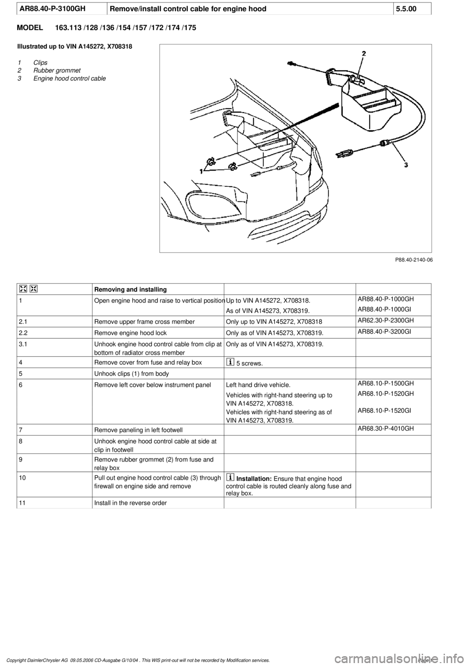
P88.40-2140-06
Illustrated up to VIN A145272, X708318
1
Clips
2
Rubber grommet
3
Engine hood control cable
Removing and installing
1
Open engine hood and raise to vertical position
Up to VIN A145272, X708318.
AR88.40-P-1000GH
As of VIN A145273, X708319.
AR88.40-P-1000GI
2.1
Remove upper frame cross member
Only up to VIN A145272, X708318
AR62.30-P-2300GH
2.2Remove engine hood lock
Only as of VIN A145273, X708319.
AR88.40-P-3200GI
3.1
Unhook engine hood control cable from clip at
bottom of radiator cross member
Only as of VIN A145273, X708319.
4
Remove cover from fuse and relay box
5 screws.
5
Unhook clips (1) from body
6
Remove left cover below instrument panel
Left hand drive vehicle.
AR68.10-P-1500GH
Vehicles with right-hand steering up to
VIN A145272, X708318.
AR68.10-P-1520GH
Vehicles with right-hand steering as of
VIN A145273, X708319.
AR68.10-P-1520GI
7
Remove paneling in left footwell
AR68.30-P-4010GH
8
Unhook engine hood control cable at side at
clip in footwell
9
Remove rubber grommet (2) from fuse and
relay box
10
Pull out engine hood control cable (3) through
firewall on engine side and remove
Installation:
Ensure that engine hood
control cable is routed cleanly along fuse and
relay box.
11
Install in the reverse order
Copyright DaimlerChrysler AG 09.05.2006 CD-Ausgabe G/10/04 . This WIS print-out will not be recorde
d by Modification services.
Page 1
Page 3216 of 4133
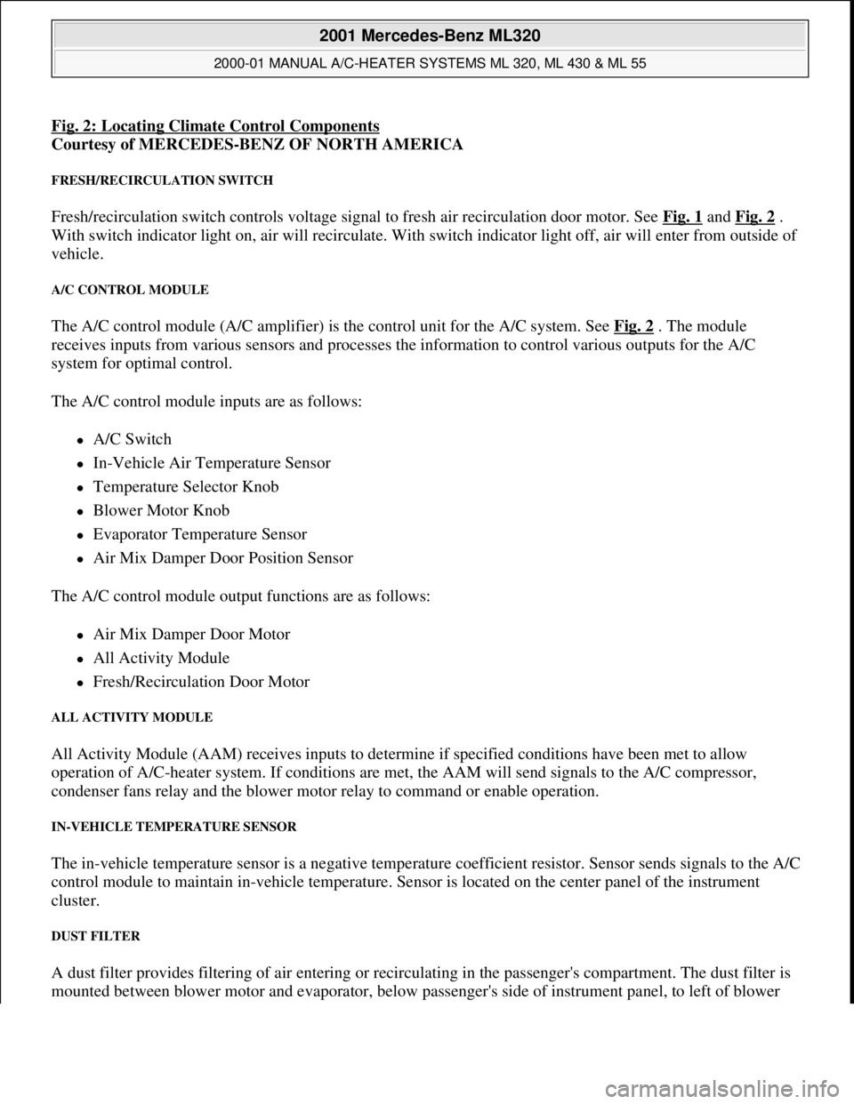
Fig. 2: Locating Climate Control Components
Courtesy of MERCEDES-BENZ OF NORTH AMERICA
FRESH/RECIRCULATION SWITCH
Fresh/recirculation switch controls voltage signal to fresh air recirculation door motor. See Fig. 1 and Fig. 2 .
With switch indicator light on, air will recirculate. With switch indicator light off, air will enter from outside of
vehicle.
A/C CONTROL MODULE
The A/C control module (A/C amplifier) is the control unit for the A/C system. See Fig. 2 . The module
receives inputs from various sensors and processes the information to control various outputs for the A/C
system for optimal control.
The A/C control module inputs are as follows:
A/C Switch
In-Vehicle Air Temperature Sensor
Temperature Selector Knob
Blower Motor Knob
Evaporator Temperature Sensor
Air Mix Damper Door Position Sensor
The A/C control module output functions are as follows:
Air Mix Damper Door Motor
All Activity Module
Fresh/Recirculation Door Motor
ALL ACTIVITY MODULE
All Activity Module (AAM) receives inputs to determine if specified conditions have been met to allow
operation of A/C-heater system. If conditions are met, the AAM will send signals to the A/C compressor,
condenser fans relay and the blower motor relay to command or enable operation.
IN-VEHICLE TEMPERATURE SENSOR
The in-vehicle temperature sensor is a negative temperature coefficient resistor. Sensor sends signals to the A/C
control module to maintain in-vehicle temperature. Sensor is located on the center panel of the instrument
cluster.
DUST FILTER
A dust filter provides filtering of air entering or recirculating in the passenger's compartment. The dust filter is
mounted between blower motor and evaporator, below passen
ger's side of instrument panel, to left of blower
2001 Mercedes-Benz ML320
2000-01 MANUAL A/C-HEATER SYSTEMS ML 320, ML 430 & ML 55
me
Saturday, October 02, 2010 3:25:10 PMPage 5 © 2006 Mitchell Repair Information Company, LLC.
Page 3225 of 4133
OUTSIDE TEMPERATURE SENSOR RESISTANCE
READING ACTUAL VALUES WITH HHT
Connect Hand-Held Tester (HHT) to DLC and follow displayed procedures. Actual values displayed on HHT
show normal operation value of A/C systems or components. See ACTUAL VALUES
table. If value is not as
specified, check system or components in order. Repair as necessary.
ACTUAL VALUES
REMOVAL & INSTALLATION
Sensor Temperature - °F (°C)Ohms
68 (20)2100
77 (25)1700
104 (40)900
122 (50)600
Step (1) Test ConditionValueSystem/Component
01.....11-14 VoltsVoltage Supply Wiring (Circuit
No. 30) & Battery
02Engine Operating At
Normal TemperatureAbout 176°F (80°C)Wiring, ECT Sensor & AAM
03Ignition ONAmbient Air Temperature
About 68°F (20°C)Wiring, Outside Temperature
Sensor & AAM
04Ignition ON, Blower At
Stage 4ON/OFFWiring, Blower Motor Relay,
Blower Motor & AAM
05Ignition ONON/OFFWiring, Engine Cooling Fan
Stage 1, Aux. Fan & AAM
08Ignition ONON/OFFWiring, Coolant Circulation Pump
Relay, Coolant Circulation Pump
& AAM
09Engine On, A/C Indicator
On, Blower Motor At
Stage 4Refrigerant Pressure At
174 psi (12 bar)(2) Refrigerant Pressure Sensor
10Engine On, A/C Indicator
On, Blower Motor At
Stage 4ON/OFF(3) AAM, A/C Compressor
11Ignition ON, Activate
A/C SystemYES/NOWiring, A/C Push Button Control
Module, AAM
(1)Step numbers not shown are not used.
(2)Check A/C refrigerant pressure switch. See A/C REFRIGERANT PRESSURE SWITCH under
ELECTRICAL TESTS.
(3)Check A/C button activation. See A/C BUTTON under ELECTRICAL TESTS.
2001 Mercedes-Benz ML320
2000-01 MANUAL A/C-HEATER SYSTEMS ML 320, ML 430 & ML 55
me
Saturday, October 02, 2010 3:25:10 PMPage 14 © 2006 Mitchell Repair Information Company, LLC.
Page 3320 of 4133
The liquefied refrigerant is routed under pressure into the fluid reservoir and flows through a stainless steel
meshing to the filter block. The pores in the filter block are matched precisely to the refrigerant's molecular size.
Thus the refrigerant can flow through the filter block.
All other matter, primarily water, is held back by this molecular filter and deposited. The cleaned refrigerant
flows over a rising pipe to the expansion valve.
Whenever the system is opened, the fluid reservoir should be replaced because of the water which has
collected there in the meantime.
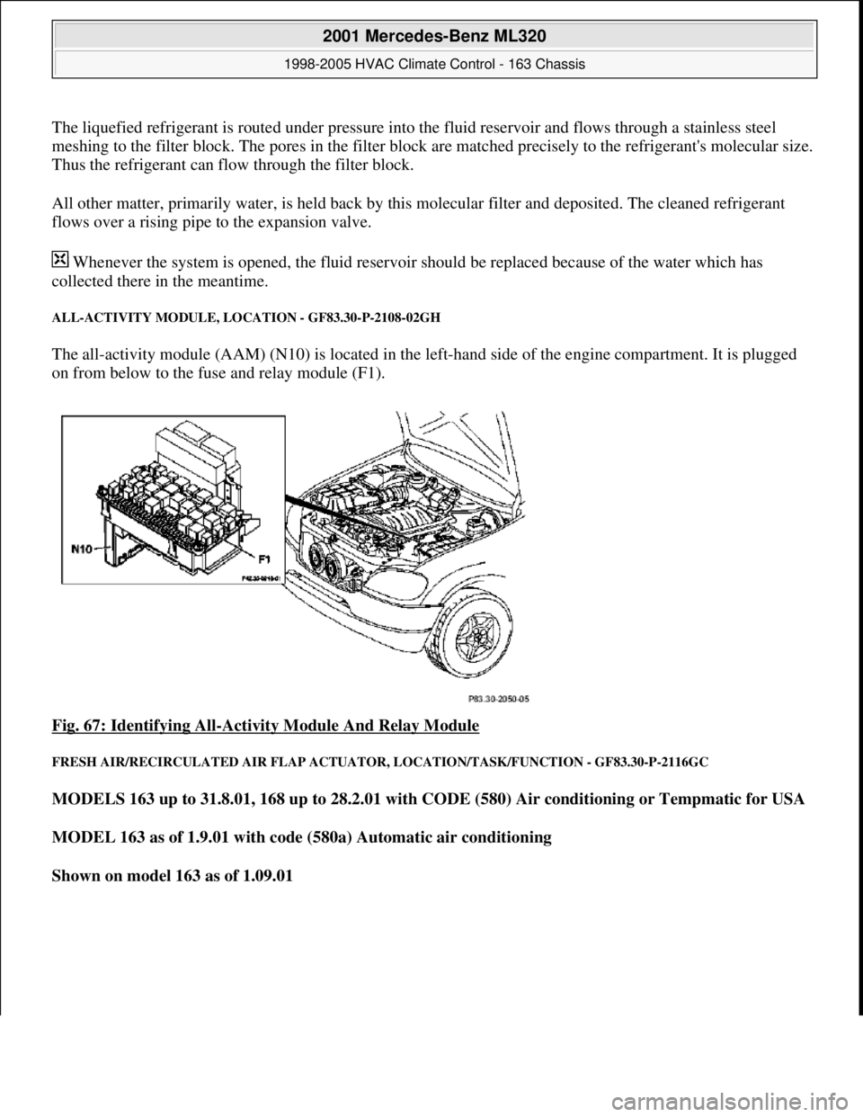
ALL-ACTIVITY MODULE, LOCATION - GF83.30-P-2108-02GH
The all-activity module (AAM) (N10) is located in the left-hand side of the engine compartment. It is plugged
on from below to the fuse and relay module (F1).
Fig. 67: Identifying All
-Activity Module And Relay Module
FRESH AIR/RECIRCULATED AIR FLAP ACTUATOR, LOCATION/TASK/FUNCTION - GF83.30-P-2116GC
MODELS 163 up to 31.8.01, 168 up to 28.2.01 with CODE (580) Air conditioning or Tempmatic for USA
MODEL 163 as of 1.9.01 with code (580a) Automatic air conditioning
Shown on model 163 as of 1.09.01
2001 Mercedes-Benz ML320
1998-2005 HVAC Climate Control - 163 Chassis
me
Saturday, October 02, 2010 3:23:15 PMPage 76 © 2006 Mitchell Repair Information Company, LLC.
Page 3343 of 4133
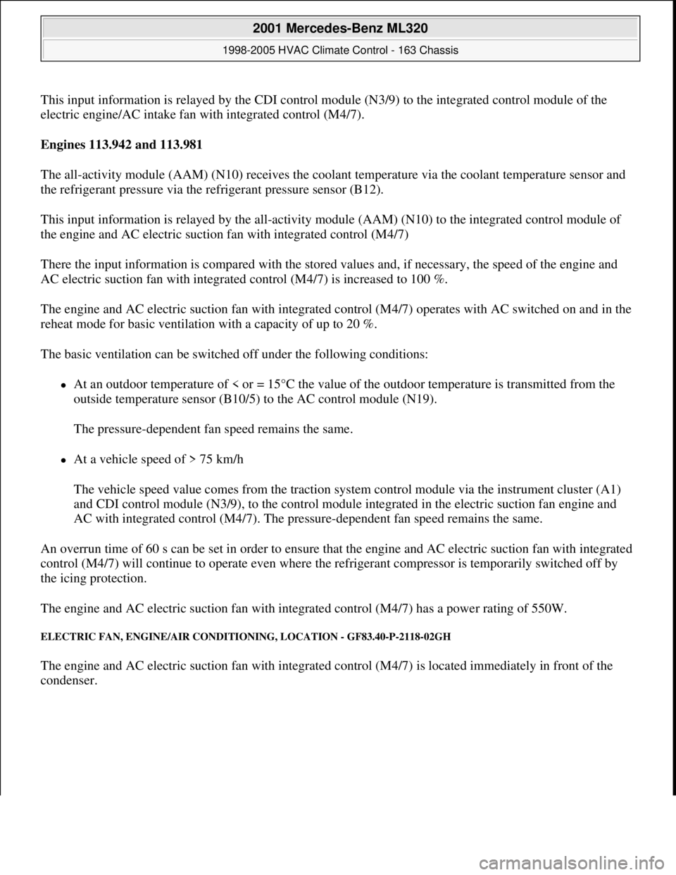
This input information is relayed by the CDI control module (N3/9) to the integrated control module of the
electric engine/AC intake fan with integrated control (M4/7).
Engines 113.942 and 113.981
The all-activity module (AAM) (N10) receives the coolant temperature via the coolant temperature sensor and
the refrigerant pressure via the refrigerant pressure sensor (B12).
This input information is relayed by the all-activity module (AAM) (N10) to the integrated control module of
the engine and AC electric suction fan with integrated control (M4/7)
There the input information is compared with the stored values and, if necessary, the speed of the engine and
AC electric suction fan with integrated control (M4/7) is increased to 100 %.
The engine and AC electric suction fan with integrated control (M4/7) operates with AC switched on and in the
reheat mode for basic ventilation with a capacity of up to 20 %.
The basic ventilation can be switched off under the following conditions:
At an outdoor temperature of < or = 15°C the value of the outdoor temperature is transmitted from the
outside temperature sensor (B10/5) to the AC control module (N19).
The pressure-dependent fan speed remains the same.
At a vehicle speed of > 75 km/h
The vehicle speed value comes from the traction system control module via the instrument cluster (A1)
and CDI control module (N3/9), to the control module integrated in the electric suction fan engine and
AC with integrated control (M4/7). The pressure-dependent fan speed remains the same.
An overrun time of 60 s can be set in order to ensure that the engine and AC electric suction fan with integrated
control (M4/7) will continue to operate even where the refrigerant compressor is temporarily switched off by
the icing protection.
The engine and AC electric suction fan with integrated control (M4/7) has a power rating of 550W.
ELECTRIC FAN, ENGINE/AIR CONDITIONING, LOCATION - GF83.40-P-2118-02GH
The engine and AC electric suction fan with integrated control (M4/7) is located immediately in front of the
condenser.
2001 Mercedes-Benz ML320
1998-2005 HVAC Climate Control - 163 Chassis
me
Saturday, October 02, 2010 3:23:16 PMPage 99 © 2006 Mitchell Repair Information Company, LLC.
Page 3401 of 4133
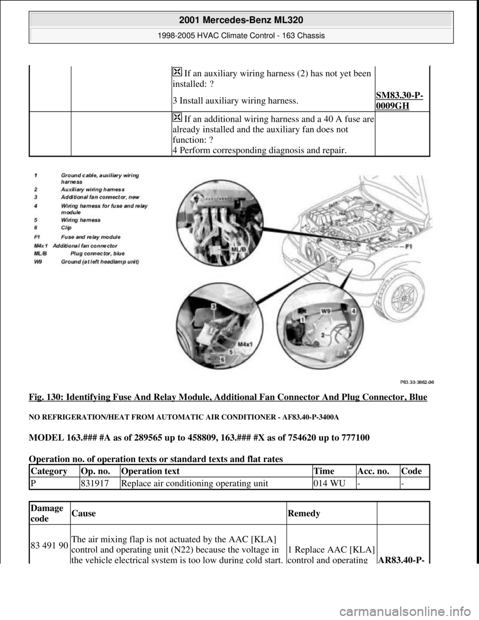
Fig. 130: Identifying Fuse And Relay Module, Additional Fan Connector And Plug Connector, Blue
NO REFRIGERATION/HEAT FROM AUTOMATIC AIR CONDITIONER - AF83.40-P-3400A
MODEL 163.### #A as of 289565 up to 458809, 163.### #X as of 754620 up to 777100
Operation no. of operation texts or standard texts and flat rates
If an auxiliary wiring harness (2) has not yet been
installed: ?
3 Install auxiliary wiring harness.SM83.30-P-
0009GH
If an additional wiring harness and a 40 A fuse are
already installed and the auxiliary fan does not
function: ?
4 Perform corresponding diagnosis and repair.
CategoryOp. no.Operation textTimeAcc. no.Code
P831917Replace air conditioning operating unit014 WU--
Damage
codeCauseRemedy
83 491 90The air mixing flap is not actuated by the AAC [KLA]
control and operating unit (N22) because the voltage in
the vehicle electrical system is too low during cold start.
1 Replace AAC [KLA]
control and operating
AR83.40-P-
2001 Mercedes-Benz ML320
1998-2005 HVAC Climate Control - 163 Chassis
me
Saturday, October 02, 2010 3:23:17 PMPage 157 © 2006 Mitchell Repair Information Company, LLC.
Page 3413 of 4133
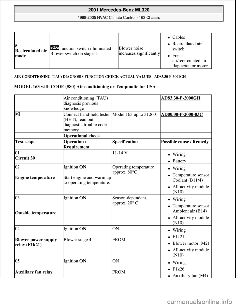
AIR CONDITIONING (TAU) DIAGNOSIS FUNCTION CHECK ACTUAL VALUES - AD83.30-P-3001GH
MODEL 163 with CODE (580) Air conditioning or Tempmatic for USA
5
Recirculated air
mode function switch illuminated
Blower switch on stage 4Blower noise
increases significantly
Cables
Recirculated air
switch
Fresh
air/recirculated air
flap actuator motor
Air conditioning (TAU)
diagnosis previous
knowledge AD83.30-P-2000GH
Connect hand-held tester
(HHT), read out
diagnostic trouble code
memoryModel 163 up to 31.8.01AD00.00-P-2000-03C
Operational check
Test scope Operation /
Requirement Specification Possible cause / Remedy
01
Circuit 30 11-14 VWiring
Battery
02Ignition ON Operating temperature
approx. 80°CWiring
Temperature sensor
Coolant (B11/4)
All-activity module
(N10)
Engine temperature Start engine and warm up
to operating temperature.
03Ignition ON Season-dependent,
approx. 20° CWiring
Temperature sensor
Ambient air (B14)
All-activity module
(N10)
Outside temperature
04Ignition ON ONWiring
F1k21
Blower motor (M2)
All-activity module
(N10)
Blower power supply
relay (F1k21) Blower stage 4FROM
05Ignition ON ONWiring
F1k26
Auxiliary fan (M4) Auxiliary fan relay FROM
2001 Mercedes-Benz ML320
1998-2005 HVAC Climate Control - 163 Chassis
me
Saturday, October 02, 2010 3:23:17 PMPage 169 © 2006 Mitchell Repair Information Company, LLC.
Page 3414 of 4133
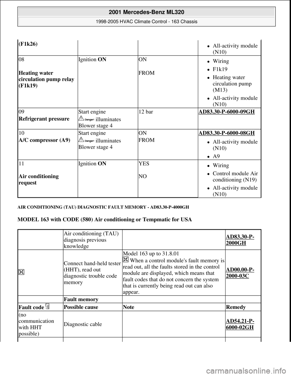
AIR CONDITIONING (TAU) DIAGNOSTIC FAULT MEMORY - AD83.30-P-4000GH
MODEL 163 with CODE (580) Air conditioning or Tempmatic for USA
(F1k26) All-activity module
(N10)
08Ignition ON ONWiring
F1k19
Heating water
circulation pump
(M13)
All-activity module
(N10)
Heating water
circulation pump relay
(F1k19) FROM
09Start engine12 barAD83.30-P-6000-09GH
Refrigerant pressure illuminates
Blower stage 4
10Start engineONAD83.30-P-6000-08GH
A/C compressor (A9) illuminates
Blower stage 4FROMAll-activity module
(N10)
A9
11Ignition ON YESWiring
Control module Air
conditioning (N19)
All-activity module
(N10)
Air conditioning
request NO
Air conditioning (TAU)
diagnosis previous
knowledge
AD83.30-P-
2000GH
Connect hand-held tester
(HHT), read out
diagnostic trouble code
memory
Model 163 up to 31.8.01
When a control module's fault memory is
read out, all the faults stored in the control
module are displayed, which means that
fault codes that do not concern the system
that is currently being read out can also
appear.
AD00.00-P-
2000-03C
Fault memory
Fault code Possible cause Note Remedy
(no
communication
with HHT
possible)
Diagnostic cable AD54.21-P-
6000-02GH
2001 Mercedes-Benz ML320
1998-2005 HVAC Climate Control - 163 Chassis
me
Saturday, October 02, 2010 3:23:17 PMPage 170 © 2006 Mitchell Repair Information Company, LLC.