1997 MERCEDES-BENZ ML320 relay
[x] Cancel search: relayPage 3475 of 4133
REMOVAL & INSTALLATION
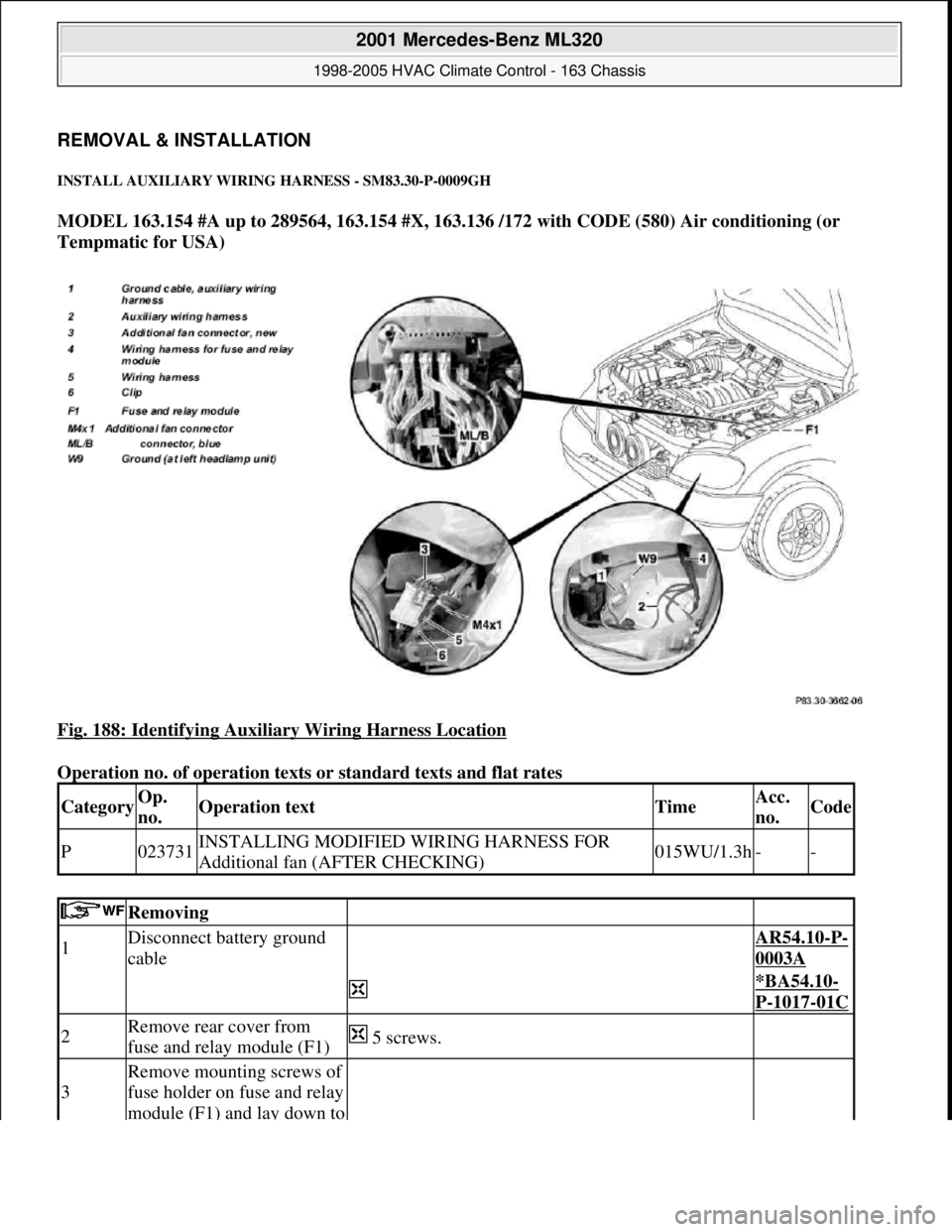
INSTALL AUXILIARY WIRING HARNESS - SM83.30-P-0009GH
MODEL 163.154 #A up to 289564, 163.154 #X, 163.136 /172 with CODE (580) Air conditioning (or
Tempmatic for USA)
Fig. 188: Identifying Auxiliary Wiring Harness Location
Operation no. of operation texts or standard texts and flat rates
CategoryOp.
no.Operation textTimeAcc.
no.Code
P023731INSTALLING MODIFIED WIRING HARNESS FOR
Additional fan (AFTER CHECKING)015WU/1.3h--
Removing
1Disconnect battery ground
cable AR54.10-P-
0003A
*BA54.10-
P-1017-01C
2Remove rear cover from
fuse and relay module (F1) 5 screws.
3
Remove mounting screws of
fuse holder on fuse and relay
module (F1) and lay down to
2001 Mercedes-Benz ML320
1998-2005 HVAC Climate Control - 163 Chassis
me
Saturday, October 02, 2010 3:23:19 PMPage 231 © 2006 Mitchell Repair Information Company, LLC.
Page 3476 of 4133
side
4
Disconnect blue connector
(ML/B) from bottom of fuse
holder
5Remove lamp unit AR82.10-P-
4730GH
6
Remove original additional
fan connector (M4x1) from
additional fan and fasten to
present wiring harness (5)
with adhesive tape on clip
(6)
Install
7
Route new additional fan
connector (3) on auxiliary
wiring harness (2) to
additional fan connector and
insert
Route along original wiring harness at rear of
installation opening of lamp unit
8
Fasten auxiliary wiring
harness (2) to original wiring
harness in area of clips with
cable straps.
9
Fasten auxiliary wiring
harness ground cable (1) to
left front ground (W9)
*BA54.10-
P-1017-01C
10
Route auxiliary wiring
harness (2) into fuse and
relay module
Route fuse and relay module along wiring harness
for fuse and relay module (4) below installation
opening of lamp unit between washer water reservoir
and fender to grommet on left side of fuse and relay
module. Remove adhesive tape from rubber
grommet, thread wiring harness through and reinstall
adhesive tape.
11
Route connection terminal
of auxiliary wiring harness
(2) to blue connector
(ML/B) at bottom of fuse
holder
12
Open housing of connector
(ML/B) and remove lead
from plug location 1
13
Separate present lead
approx. 100 mm in front
connection terminal
Insert connection terminal
for auxiliary wiring harness
Ensure that connection terminal arrests correctly
2001 Mercedes-Benz ML320
1998-2005 HVAC Climate Control - 163 Chassis
me
Saturday, October 02, 2010 3:23:19 PMPage 232 © 2006 Mitchell Repair Information Company, LLC.
Page 3477 of 4133
Battery
Parts ordering notes
14
(2) into plug location 1 of
connector (ML/B) and close
connector housing.in connector.
15
Insert blue connector
(ML/B) at bottom of fuse
holder and fasten auxiliary
wiring harness (2) to
separated lead with adhesive
tape
Ensure that stripped wire ends are insulated with
adhesive tape.
16
Fasten fuse holder to fuse
and relay module with
screws
17Insert new 40 A fuse at
position f44 in fuse holder The larger line diameter of the auxiliary wiring
harness (2) allows installation of a 40 A fuse.
18Install in the reverse order
19Check function of additional
fan
NumberDesignationModel 163
BA54.10-P-1017-01CNut, ground cable to bodyNm18
Part no.DesignationQuantity
163 540 00 35Auxiliary wiring harness1
910153 000000Fuse, 40 A1
2001 Mercedes-Benz ML320
1998-2005 HVAC Climate Control - 163 Chassis
me
Saturday, October 02, 2010 3:23:19 PMPage 233 © 2006 Mitchell Repair Information Company, LLC.
Page 3483 of 4133

GF54.30-P-3002A
Indicator and warning signals triggered over direct lines, function
24.10.96
MODEL
129, 140 as of 1.6.96,
163, 168, 170,
202 as of 1.8.96,
208 up to 31.7.99,
210 as of 1.6.96 up to 30.6.99
Indicator and warning signals
Indicator lamps for left turn signal (A1e1) and right turn signal
(A1e2)
The signal in models 129, 140, 170, 202 comes from the
combination relay (turn signals with trailer coupling, rear
window defroster, wiper motor, anti-theft alarm system)
(N10/2), and in model 210 from the multifunction control
module (N10-1) or the driver's side signal acquisition and
actuation module (SAM) (N10/1).
In model 168 the entire turn signal control is located in the
instrument cluster (A1).
Brake fluid / parking brake warning lamp (A1e7)
The signal for the brake fluid comes direct from the brake fluid level switch (S11) (except model 163).
(The signal for the parking brake comes over CAN.)
Low windshield washer fluid level warning lamp (A1e13) except
models 163 and 168
See
document: Coolant/washer fluid level voltage coding, task /
function
-----------------------------------------------------------------------------------------
Low windshield washer fluid level warning lamp (A1e13) as of
01.09.01 for model 163
See document: Displaying washer fluid level, function
Low engine coolant level warning lamp (A1e11) except models
163 and 168
See
document: Coolant/washer fluid level voltage coding, task /
function
Low engine coolant level warning lamp (A1e11) model 163 as of
3.99
See
document: Displaying coolant level, function
Coolant level and temperature warning lamp (A1e11) model 168
as of 9.99
See
document: Displaying coolant level, function
Fuel reserve warning lamp (A1e4)
When the reserve fuel level is reached, this lamp lights up and
goes out again only after refueling is detected. If the vehicle is
refueled with the ignition ON, refueling is detected only if at
least 7 liters of fuel are added.
-----------------------------------------------------------------------------------------
AIRBAG OFF indicator lamp (A1e56), only model 163 except
I
The signal comes from the emergency tensioning retractor
(ETR) control module with airbag (AB, N2/2)
Generator charge indicator/warning lamp (A1e5)
See document: Terminal 61 and terminal 61e, charge indicator
lamp, exterior lamp failure, function
Seatbelt/backrest lock warning lamp (A1e9)
The seat belt warning lamp is only used in a few national
versions, and is actuated direct by a seat belt buckle switch
(normally closed contact). After engine start, the lamp flashes
for a short time (approx. 6 seconds).
In model 129 if this lamp fails to go out after flashing briefly, but
continues to shine constantly, then the seat backrest is not
locked.
Exterior lamp failure indicator lamp (A1e14)
The signal comes from the lamp failure monitor
See document: Terminal 61 and terminal 61e, charge indicator
lamp, exterior lamp failure, function
Hydraulic fluid level warning lamp (A1e37)
The signal comes direct from the ADS level control oil level
switch (S44).
ADS warning lamp, suspension (A1e27) The signal comes from the ADS control module, suspension
(N51).
SRS airbag malfunction indicator lamp (A1e15)
The signal comes from the emergency tensioning retractor
(ETR) control module with airbag (AB, N2/2)
Voltage coding of coolant / windshield washer
fluid level, function
Except models 163 and 168
GF54.30-P-3006A
Displaying coolant level, function
Model 163 as of 3.99
GF54.30-P-3028GH
Model 168 as of 9.99
GF54.30-P-3028GC
Terminal 61 and terminal 61e, charge
indicator lamp, exterior lamp failure, function
GF54.30-P-3007A
Copyright DaimlerChrysler AG 04.06.2006 CD-Ausgabe G/10/04 . This WIS print-out will not be recorde
d by Modification services.
Page 1
Page 3495 of 4133

AD54.30-P-6000-01GH
Instrument cluster, testing electrical system IC
Model 163
t
A
Scope of test
Measuring instrument/
Test connection
Operation/
Requirement
Specified value
D
Possible cause/
Remedy
1.0Instrument cluster (A1)
Voltage supply,
terminal 30
3 w
(A.3)
A1
cL
11
(A.11)
Ignition:
OFF
Remove A1
Coupling "A" (18-pin)
disconnected
11
-
14 V
D
Fuse f13 in fuse and relay
box F1
D
Cables
Value in order
#
t
1.1
1.1
Voltage supply,
terminal 15
3 w
(A.3)
A1
cL
9
(A.9)
Ignition: ON
11
-
14 V
D
Fuse f22 in fuse and relay
box F1
D
Cables
Value in order
#
t
1.2
1.2
Voltage supply,
terminal 15R
3 w
(A.3)
A1
cL
7
(A.7)
Ignition: ON
11
-
14 V
D
Fuse f10 in fuse and relay
box F1
D
Cables
Value in order
#
D
A1
Copyright DaimlerChrysler AG 05.06.2006 CD-Ausgabe G/10/04 . This WIS print-out will not be recorde
d by Modification services.
Page 1
Page 3576 of 4133
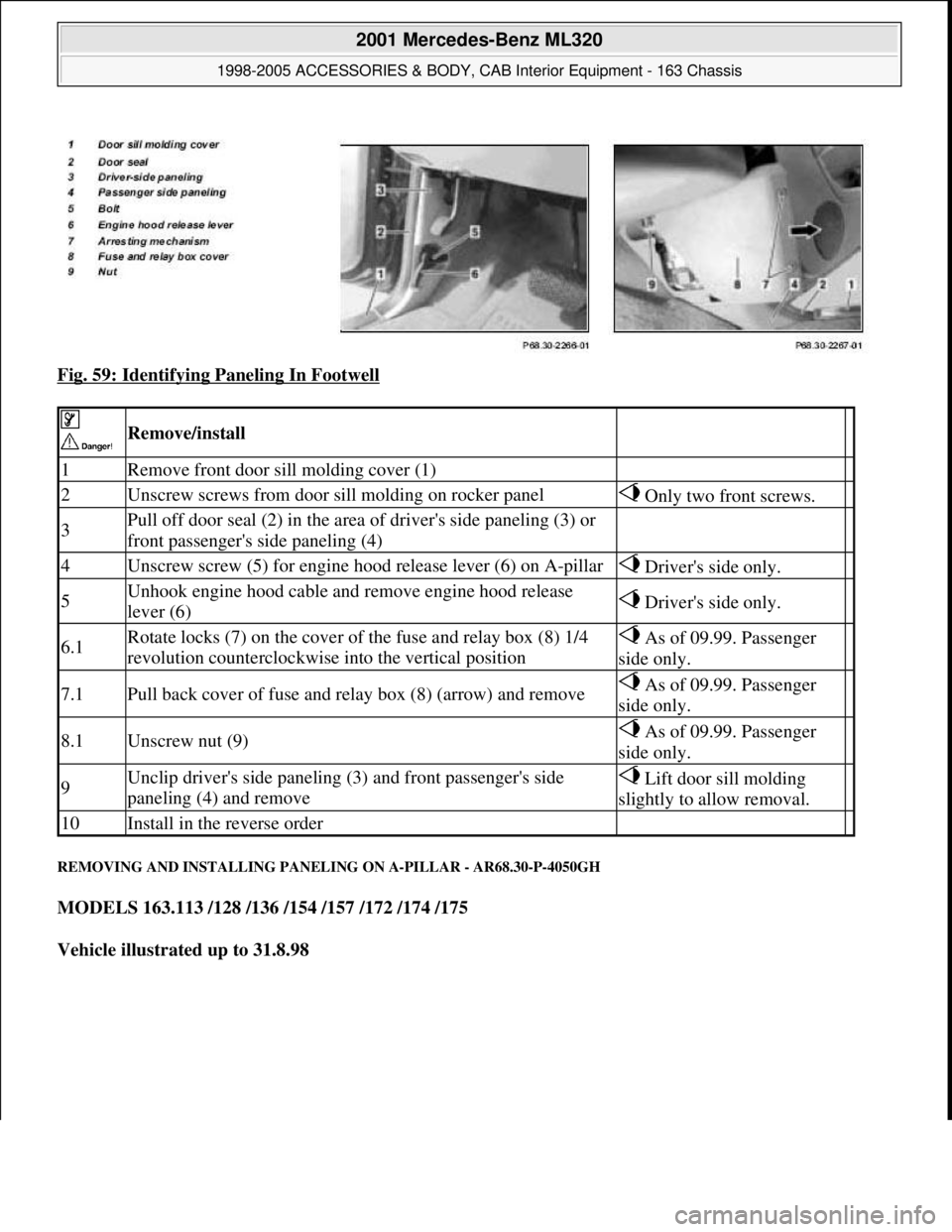
Fig. 59: Identifying Paneling In Footwell
REMOVING AND INSTALLING PANELING ON A-PILLAR - AR68.30-P-4050GH
MODELS 163.113 /128 /136 /154 /157 /172 /174 /175
Vehicle illustrated up to 31.8.98
Remove/install
1Remove front door sill molding cover (1)
2Unscrew screws from door sill molding on rocker panel Only two front screws.
3Pull off door seal (2) in the area of driver's side paneling (3) or
front passenger's side paneling (4)
4Unscrew screw (5) for engine hood release lever (6) on A-pillar Driver's side only.
5Unhook engine hood cable and remove engine hood release
lever (6) Driver's side only.
6.1Rotate locks (7) on the cover of the fuse and relay box (8) 1/4
revolution counterclockwise into the vertical position As of 09.99. Passenger
side only.
7.1Pull back cover of fuse and relay box (8) (arrow) and remove As of 09.99. Passenger
side only.
8.1Unscrew nut (9) As of 09.99. Passenger
side only.
9Unclip driver's side paneling (3) and front passenger's side
paneling (4) and remove Lift door sill molding
slightly to allow removal.
10Install in the reverse order
2001 Mercedes-Benz ML320
1998-2005 ACCESSORIES & BODY, CAB Interior Equipment - 163 Chassis
me
Saturday, October 02, 2010 3:35:22 PMPage 58 © 2006 Mitchell Repair Information Company, LLC.
Page 3730 of 4133

GF77.20-P-2003GH
Opening pop-up roof, function
19.2.97
MODEL
163 with CODE (414a) Electric glass sliding/pop-up roof
Function prerequisites
D
Voltage not too low or too high
D
Switch-on conditions for convenience control fulfilled
D
Sliding/pop-up roof synchronized
Function
When
switch (SHD, S13/2)
is actuated continuously, circuit 30 is
switched through to the
sliding/pop-up roof (M12)
and the pop-up
roof opens.
The function "Open pop-up roof" is executed as long as
D
switch (SHD, S13/2)
is actuated and
D
the pop-up roof has not yet reached the end position and
D
lock-up is not recognized.
If the sliding/pop-up roof is desynchronized, it moves only in the pop-
up roof direction each time the
switch (SHD, S13/2)
is actuated. This
means that it is possible to move to the zero
position for synchronizing. After successful
synchronization
, the
sliding/pop-up roof can be controlled again without limitation.
Vehicles
up to 11.99:
The power for the
sliding/pop-up roof (M12)
is supplied via a
fuse directly to c. 30.
The power for the
switch (SR, S13/2)
is supplied via the
convenience relay (F1k14)
, which is actuated by the all-
activity module (AAM, N10).
Vehicles
as of 12.99:
The power for the
sliding/pop-up roof (M12)
is supplied via a
fuse directly to c. 30. The power for the
switch (SHD, S13/2) is
supplied via a lead to the
extended-activity module (EAM,
N10/1) , this power is switched through only when the switch-on
conditions for the convenience control are fulfilled and the EAM
is coded accordingly.
Closing sliding /pop-up roof, function
GF77.20-P-2002GH
Sliding /pop-up roof lock-up recognition,
function
GF77.20-P-3000GH
Sliding /pop-up roof position measurement,
function
GF77.20-P-3001GH
Synchronizing sliding /pop-up roof, function
GF77.20-P-3002GH
Convenience control
GF72.29-P-2002GH
All-activity module (AAM)
up to 11.99
GF54.21-P-4100GH
Extended-activity module, location/
purpose/design/function
as of 12.99
GF54.21-P-4107GK
Copyright DaimlerChrysler AG 04.08.2006 CD-Ausgabe G/10/04 . This WIS print-out will not be recorde
d by Modification services.
Page 1
Page 3872 of 4133
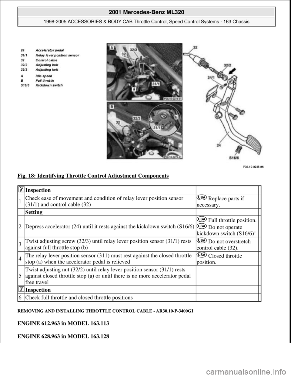
Fig. 18: Identifying Throttle Control Adjustment Components
REMOVING AND INSTALLING THROTTLE CONTROL CABLE - AR30.10-P-3400GI
ENGINE 612.963 in MODEL 163.113
ENGINE 628.963 in MODEL 163.128
Inspection
1Check ease of movement and condition of relay lever position sensor
(31/1) and control cable (32) Replace parts if
necessary.
Setting
2Depress accelerator (24) until it rests against the kickdown switch (S16/6)
Full throttle position.
Do not operate
kickdown switch (S16/6)!
3Twist adjusting screw (32/3) until relay lever position sensor (31/1) rests
against full throttle stop (b) Do not overstretch
control cable (32).
4The relay lever position sensor (311) must rest against the closed throttle
stop (a) when the accelerator pedal is relieved Closed throttle
position.
5
Twist adjusting nut (32/2) until relay lever position sensor (31/1) rests
against closed throttle stop (a) or until there is no more accelerator pedal
free travel
Inspection
6Check full throttle and closed throttle positions
2001 Mercedes-Benz ML320
1998-2005 ACCESSORIES & BODY CAB Throttle Control, Speed Control Systems - 163 Chassis
me
Saturday, October 02, 2010 3:36:28 PMPage 32 © 2006 Mitchell Repair Information Company, LLC.