1997 MERCEDES-BENZ ML320 fuel pressure
[x] Cancel search: fuel pressurePage 3050 of 4133
SAFETY PRECAUTIONS FOR NEW VEHICLES THAT ARE BEING PUT IN STORAGE - AP00.70-P-1000ZZ
MODELS all
and rear axle
Frame
New vehicles in the
context of this description
are vehicles for which no
inspection has been carried
out to date. For other
vehicles, the instructions
in the Specifications for
Service Products apply
In areas in which
extremely high corrosive
attacks can be expected
from experience, the
measures given here are
not always sufficient even
for new vehiclesExport countries
In these cases, proceed in
accordance with
Specifications for Service
products.
Treatment of battery if
vehicle taken out of
service AR54.10-P-0006EA
Treatment of tire inflation
pressure if vehicle taken
out of serviceFor vehicles which will be
stored for longer than 2
months, the tire inflation
pressure should be
increased to approx. 4 bar
to prevent flattening of the
contact surface.
Treatment of break system
if vehicle taken out of
serviceWarm up service brake so
that adhering moisture at
the brake disks and the
brake pads evaporates.
This prevents the brake
pad from becoming stuck
to the brake disks.
Release parking brake.
The vehicle must be
secured by engaging a
gear/park pawl or by using
wedges.
Treatment of fuel system
if vehicle taken out of To protect the fuel tank
from corrosion, we
2004 Mercedes-Benz ML350
1998-2005 GENINFO Overall vehicle - 163 Chassis
me
Saturday, October 02, 2010 3:47:52 PMPage 405 © 2006 Mitchell Repair Information Company, LLC.
Page 3176 of 4133
Because the brake fluid also absorbs moisture through the vent bore on the expansion reservoir, the wheel brake
cylinder and the brake hoses, the brake fluid has to be changed for safety reasons at regular intervals, best done
in the spring. When performing this change, make sure that the old fluid is also drained off the clutch system.
Generally, it is vital for the brake/clutch system to be completely drained before being filled with new fluid!
For the above-mentioned reasons, used brake fluid must not be used again.
The brake fluid is amber in color and thus can be easily confused with mineral products.
Therefore, brake fluids should always only be taken from original containers and stored separately from other
mineral oils and fluids.
When performing maintenance operations and repairs on brake parts, make sure that fuel, mineral oil, grease or
suchlike do not enter the brake system. Hydrocarbon-based materials will lead to swelling of the elastomers in
the brake and clutch system and - even in low concentrations - will suffice to cause total failure of the systems.
Only new brake fluid may be used as a rinsing and cleaning agent for the cylinders, lines and the expansion
reservoir of the hydraulic brake system.
Experience shows that before handling brake fluid, the hands must be cleaned and any oil and grease removed.
Brake fluid acts aggressively towards paint and color. In the event of any brake fluid spills or splashes, it must
be rinsed away immediately using copious amounts of water (do not rub it away).
Brake fluid disposal
When disposing of brake fluid, the relevant national specifications must be observed. It is advisable to try to
have the brake fluid disposed of as economic good; this is contingent on
Strict separation of used brake fluid from other materials;
Presence of a disposal channel, which justifies its classification as an economic good, i.e. a proper
alternate usage must be assured.
If this procedure is not possible, used brake fluid is to be disposed of together with any, e.g. paint residue,
solvents and suchlike. Any adding of used oil must be avoided, as it will result in difficulties, if the used oil is to
be recycled; in several countries this is prohibited by the legislators.
MISCELLANEOUS NOTES
NOTES ON SCRAPPING GAS-FILLED HYDRAULIC COMPONENTS - OS00.00-P-1000-01A
all
Unusable gas pressure dampers, spring accumulators, pressure reservoirs and impact absorbers have to be
depressurized before being scrapped according to the respective valid accident prevention regulations. These
safety measures are necessary because gas pressurized hydraulic parts can explode if heat is applied. A risk of
explosion is
given, e.g. when scrapping with cutting torches, smelting or if gas pressurized parts in landfills start
2004 Mercedes-Benz ML350
1998-2005 GENINFO Overall vehicle - 163 Chassis
me
Saturday, October 02, 2010 3:47:57 PMPage 531 © 2006 Mitchell Repair Information Company, LLC.
Page 3186 of 4133
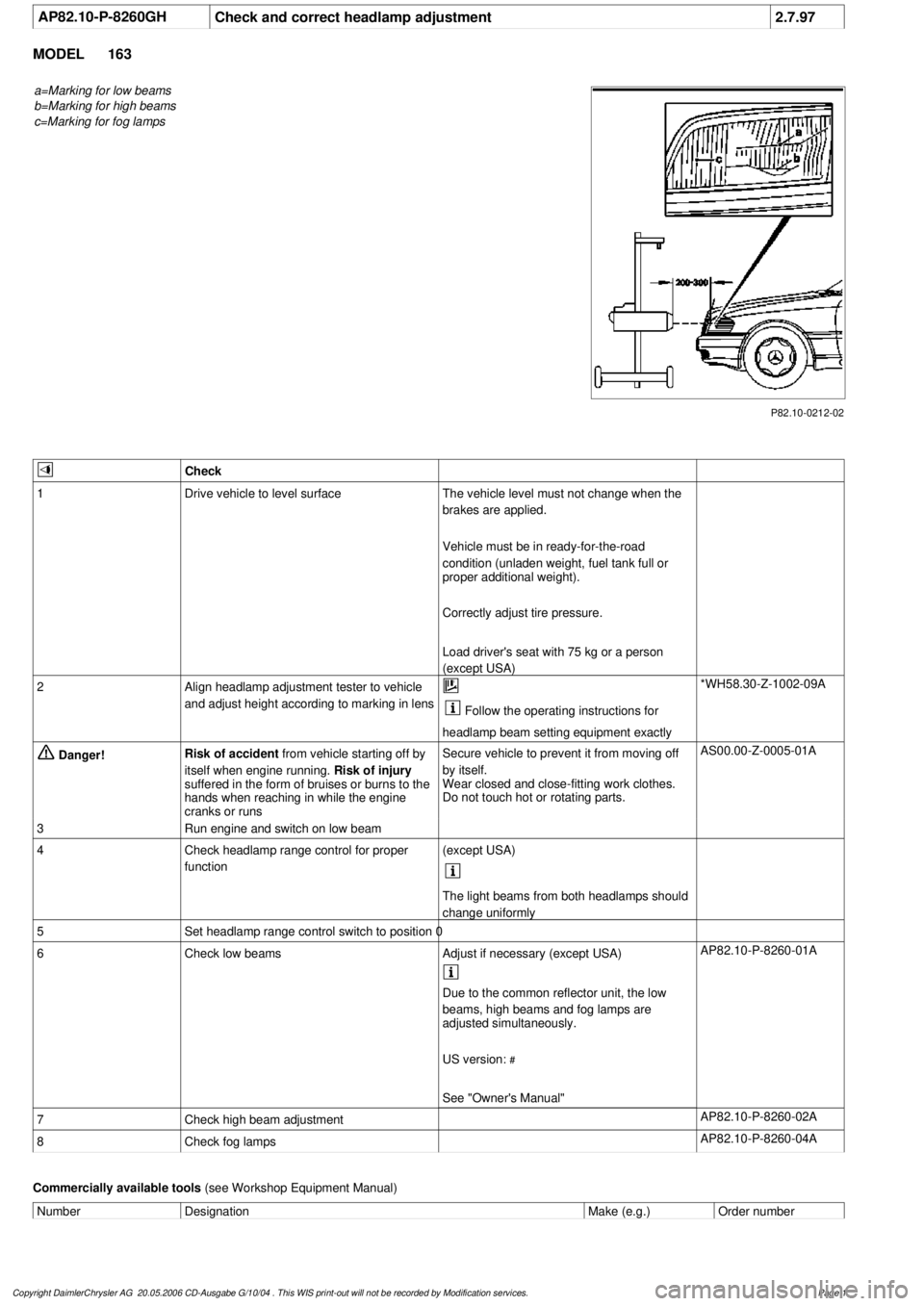
AP82.10-P-8260GH
Check and correct headlamp adjustment
2.7.97
MODEL
163
a=Marking for low beams
b=Marking for high beams
c=Marking for fog lamps
P82.10-0212-02
Check
1
Drive vehicle to level surface
The vehicle level must not change when the
brakes are applied.
Vehicle must be in ready-for-the-road
condition (unladen weight, fuel tank full or
proper additional weight).
Correctly adjust tire pressure.
Load driver's seat with 75 kg or a person
(except USA)
2
Align headlamp adjustment tester to vehicle
and adjust height according to marking in lens
Follow the operating instructions for
headlamp beam setting equipment exactly
*WH58.30-Z-1002-09A
Danger!
Risk of accident
from vehicle starting off by
itself when engine running.
Risk of injury
suffered in the form of bruises or burns to the
hands when reaching in while the engine
cranks or runs
Secure vehicle to prevent it from moving off
by itself.
Wear closed and close-fitting work clothes.
Do not touch hot or rotating parts.
AS00.00-Z-0005-01A
3
Run engine and switch on low beam
4
Check headlamp range control for proper
function
(except USA)
The light beams from both headlamps should
change uniformly
5
Set headlamp range control switch to position 0
6
Check low beams
Adjust if necessary (except USA)
AP82.10-P-8260-01A
Due to the common reflector unit, the low
beams, high beams and fog lamps are
adjusted simultaneously.
US version:
#
See "Owner's Manual"
7
Check high beam adjustment
AP82.10-P-8260-02A
8
Check fog lamps
AP82.10-P-8260-04A
Commercially available tools
(see Workshop Equipment Manual)
Number
Designation
Make (e.g.)
Order number
Copyright DaimlerChrysler AG 20.05.2006 CD-Ausgabe G/10/04 . This WIS print-out will not be recorde
d by Modification services.
Page 1
Page 3484 of 4133

AH40.10-P-9411-01A
Information on tires/rims
Model 124, 129, 140, 163, 168, 169,
170, 171, 199, 201, 202, 203, 208, 209,
210, 211, 215, 219, 220, 230, 240, 414,
450, 452,
639
Tires
D
For service conversions, the tire/disc wheel specifications and
dimensions should be compared with the entries in the
registration papers.
D
When mounting tires, the tires and rims must be carefully
matched in order to guarantee the concentricity of the wheel.
Identification of matching points on:
- Tires with a colored dot on the outside of the tire,
- Sheet steel disk wheel by a colored dot or punch mark on the
outside of the wheel,
- Perform this operation at the valve stem hole on light-alloy
disk wheels
With an additional paint spot or punch mark in the rim base
for the 140 Model Series.
D
Always replace the rubber valve.
-----------------------------------------------------------------------------------------
D
Damaged and defective tires must always be replaced. The
repair methods employed in the tire trade are not approved by
Mercedes-Benz. Small nicks (<0.8mm) on the tire's sidewall do
not usually pose a cause for concern, and continued use of
such tires is approved
D When replacing just one tire, install it on the front of the vehicle.
This does not apply to vehicles with different tires of varying
specifications on the front and rear wheels.
D
Only use tires listed in the valid Service Information bulletins
and repair instructions.
D
If the permissible maximum speed of an M+S tire is below the
maximum speed of the vehicle, an appropriate adhesive plate
must be attached in the driver's field of view.
-----------------------------------------------------------------------------------------
D
Tires permissible for higher speeds may be used.
D
Always fit all rims with tires of the same design, make and
version.
-----------------------------------------------------------------------------------------
D
Run in new tires for approx. 100 km at moderate speed.
D
Handed tires must be installed according to the arrow on the
side wall of the tire.
D
Tires are subject to an aging process with negative effects on
the properties of the tire. In order to ensure optimum
effectiveness in winter, M+S tires should not be used for longer
than 3 years.
-----------------------------------------------------------------------------------------
Tire pressure
(For specified values see tire pressure table in the fuel filler flap, on
the Vaneo BM 414 see B-pillar on the passenger side).
Too low tire pressure increases the rolling resistance and increases
the flexing energy of the tire. This causes the critical temperature limit
to be exceeded (carcass detachment) and destroys the tire. Respond
to loss of tire pressure by determining the source and replacing the
tire as indicated.
Cleaning
Using a spray wand with high-pressure nozzles to clean the wheel
can lead to tire damage. Such damage occurs especially on the tire
side walls. The following should be observed when using flat jet
nozzles:
D
Maintain a minimum distance of 300 mm
D
Do not direct the water jet at a single point on the surface of the
tire for any length of time.
-----------------------------------------------------------------------------------------
Mounting in bearings
Before putting into storage, clean tires thoroughly and check for
damage and adequate tread depth. Mark the position and running
direction of the tires with chalk. Do not store tires outdoors. Under the
influence of sunlight, heat, moving air and ozone the rubber looses
elasticity and strength, ages more quickly and becomes cracked.
Storage areas should be dry, cool and dark. Avoid drafts by keeping
doors and windows closed as much as possible. Do not bring tires
into contact with gasoline, oil or other greases as they dissolve the
rubber.
Disposal
Collection, storage and disposal should be performed in accordance
with the legal requirements and the company's own regulations.
-----------------------------------------------------------------------------------------
Copyright DaimlerChrysler AG 06.07.2006 CD-Ausgabe G/10/04 . This WIS print-out will not be recorde
d by Modification services.
Page 1
Page 3778 of 4133
8.1
Check wheel sensor, valve body and sealing
rubber for damage
Vehicles with tire pressure monitor (code 475)
Do not remove wheel sensor for this.
Do not use compressed air, solvents or
detergents to clean the wheel sensor. Wipe
off dirt with a clean, lint-free cloth only.
Do not retighten the female torx bolt and
union nut.
Replace all valve components of wheel
electronics if:
D
The wheel sensor mounting bolt or union
nut is visibly loose.
Replace the wheel sensor if:
D
The wheel sensor is obviously damaged.
D
Tire sealant was used.
Install new wheel sensors:
#
Replace wheel sensor.
AR40.15-P-0080A
8.2
Install new valve (43g).
Vehicles without tire pressure monitor (code
475)
9
Checking condition of rim
AR40.10-P-1010-01A
Mounting
10
Moisten rim flange and tire beads with soapy
water and align assembly head at a small
distance (X, Y) to the disk wheel
Only use soapy water for fitting and
removing tires.
11
Place tire obliquely on the rim and pull on
over the rim flange using the tire installer
Position wheels with wheel sensors so
that the wheel sensor is approximately 180°
opposite the mounting head.
Do not apply compressive force to the wheel
sensor otherwise it will be damaged.
Observe the running direction on tires with
specified running direction.
Put as little stress as possible on bead
area.
12
Align the match points of the tire and disk
wheel with each other and remove the disk
wheel with tire from the tire mounting device
13
Inflate tires without valve element up to max.
3 bar
Do
not
unscrew valve element on disk
wheels with tire pressure monitor sensor.
The tire must slide evenly over the safety
shoulders of the disk wheel, otherwise coat
the tire beads with soapy water again.
14
Screw the valve element into the valve (43g)
and adjust the tire inflation pressure to the
specified value
Observe the tire pressure information in
the fuel filler flap of the vehicle.
15
Balance wheel
AR40.10-P-1040A
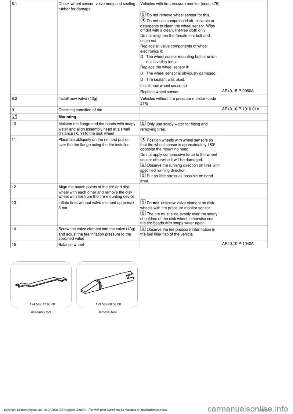
124 589 17 63 00 129 589 00 59 00
Removal tool
Assembly tool
Copyright DaimlerChrysler AG 06.07.2006 CD-Ausgabe G/10/04 . This WIS print-out will not be recorde
d by Modification services.
Page 2
Page 3832 of 4133

SI47.10-P-0004A
Service Information: Procedure when tank is filled with incorrect fuel
19.12.00
MODEL
202 with ENGINE 611
MODEL
203 with ENGINE 611, 612, 646
MODEL
210 with ENGINE 611, 612, 613
MODEL
220 with ENGINE 613, 628, 648
MODEL
163 with ENGINE 612, 628
MODEL
168 with ENGINE 668
MODEL
209 with ENGINE 612
MODEL
211 with ENGINE 628, 646, 647, 648
MODEL
463 with ENGINE 612, 628
Modification notes
26.7.04
Engines have been added and procedure has been updated
Incorrect refueling of diesel-power vehicles with a common rail
injection system. Please be aware that if the customer fills the fuel
tank with the wrong type of fuel, this is the customer's fault and
cannot be submitted as a warranty claim.
If the diesel-powered vehicle with a common rail injection system has
been refueled with gasoline, follow the steps below:
1.
If the engine was not started after fuel tank is filled with the wrong
type of fuel, then emptying the fuel tank and cleaning the fuel low-
pressure lines should be enough to solve the problem.
2.
If the engine was started after fuel tank was filled with wrong type
of fuel:
On engines 611, 612, 613, 668:
-
On the rail, open the low pressure connection of the high
pressure pump return (plastic connection in area of pressure
regulator valve) and check connecting point in rail for chips.
On engine 646, 647, 648, 628:
-
Disconnect Y-distributor unit (return line HDP/Rail) at the output
and, with ignition ON, collect the fuel in a clean container. Check
fuel for metal shavings.
If the high pressure pump is not damaged and there are no metal
shavings in the injection system:
-
As in step 1, empty fuel as per the guidelines and clean the fuel
low-pressure lines. In addition to this, remove/install/replace the
high-pressure pump and fuel filter.
If metal shavings are found in the fuel
system or the high pressure pump drive is
damaged:
#
b
Engine runs rough, surges or does not start
ENGINE 611 in MODEL 203, 202, 210
ENGINE 612 in MODEL 163, 203, 210, 209
ENGINE 613 in MODEL 210, 220
ENGINE 628 in MODEL 163, 220, 211
ENGINE 646 in MODEL 203, 211
ENGINE 647 in MODEL 211
ENGINE 648 in MODEL 220, 211
ENGINE 668 in MODEL 168
ENGINE 612, 628 in MODEL 463
AF07.00-P-9000B
Copyright DaimlerChrysler AG 28.05.2006 CD-Ausgabe G/10/04 . This WIS print-out will not be recorde
d by Modification services.
Page 1
Page 3909 of 4133
1998-2005 SUSPENSION
Suspension - 163 Chassis
GENERAL INFORMATION
GENERAL NOTES ON WORKING ON VEHICLES WITH LEVEL CONTROL/ADS - AH32.00-P-0002-01A
All models with code 216b, 216c, 217a, 480
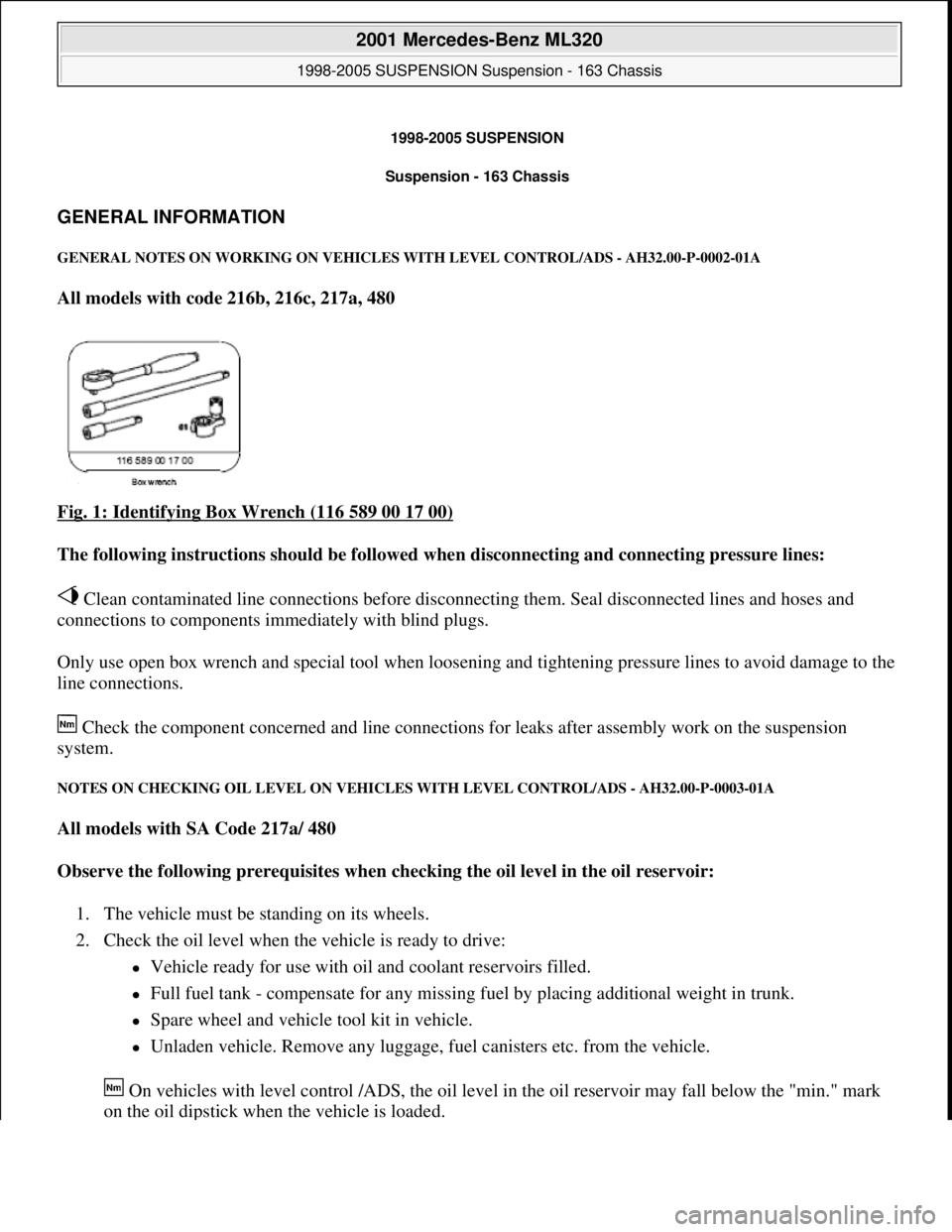
Fig. 1: Identifying Box Wrench (116 589 00 17 00)
The following instructions should be followed when disconnecting and connecting pressure lines:
Clean contaminated line connections before disconnecting them. Seal disconnected lines and hoses and
connections to components immediately with blind plugs.
Only use open box wrench and special tool when loosening and tightening pressure lines to avoid damage to the
line connections.
Check the component concerned and line connections for leaks after assembly work on the suspension
system.
NOTES ON CHECKING OIL LEVEL ON VEHICLES WITH LEVEL CONTROL/ADS - AH32.00-P-0003-01A
All models with SA Code 217a/ 480
Observe the following prerequisites when checking the oil level in the oil reservoir:
1. The vehicle must be standing on its wheels.
2. Check the oil level when the vehicle is ready to drive:
Vehicle ready for use with oil and coolant reservoirs filled.
Full fuel tank - compensate for any missing fuel by placing additional weight in trunk.
Spare wheel and vehicle tool kit in vehicle.
Unladen vehicle. Remove any luggage, fuel canisters etc. from the vehicle.
On vehicles with level control /ADS, the oil level in the oil reservoir may fall below the "min." mark
on the oil dipstick when the vehicle is loaded.
2001 Mercedes-Benz ML320
1998-2005 SUSPENSION Suspension - 163 Chassis
2001 Mercedes-Benz ML320
1998-2005 SUSPENSION Suspension - 163 Chassis
me
Saturday, October 02, 2010 3:37:35 PMPage 1 © 2006 Mitchell Repair Information Company, LLC.
me
Saturday, October 02, 2010 3:37:38 PMPage 1 © 2006 Mitchell Repair Information Company, LLC.
Page 3960 of 4133

AD54.30-P-5000-03A
Directly controlled display instruments
troubleshooting chart IC
Directly controlled display instruments or indicator
lamp/warning message:
D
Outside temperature indicator
D
Fuel gauge
D
Oil pressure gauge (models 129 and 140 only)
D
Left turn signal indicator lamp
D
Right turn signal indicator lamp
D
High beam indicator lamp
D
Fuel reserve indicator lamp
D
Airbag SRS indicator lamp/MIL
D
AIRBAG OFF indicator lamp (only model 163 except
I )
D
Low brake fluid level/parking brake indicator lamp (only brake
fluid direct)
(both functions via CAN on model 163)
D
Low windshield washer fluid level indicator lamp (except
models 163 and 168)
D
Low ECL indicator lamp (except models 163 and 168)
D
Generator charge indicator lamp
D
Seat belt reminder lamp
D
Seat belt/backrest lock reminder lamp
D
Exterior lamp failure indicator lamp
D
Hydraulic fluid level indicator lamp (models 202 and 210 only)
D
ADS MIL, suspension
D
Turn signal clicking
D
Seat belt reminder lamp
D
Light reminder lamp
D
Key reminder lamp
D
Soft top reminder lamp (model 170 only)
D
Steering lock warning lamp (
I )
Copyright DaimlerChrysler AG 05.06.2006 CD-Ausgabe G/10/04 . This WIS print-out will not be recorde
d by Modification services.
Page 1