1997 MERCEDES-BENZ ML320 fuel pressure
[x] Cancel search: fuel pressurePage 1162 of 4133
and skin caused
by contact with
fuel
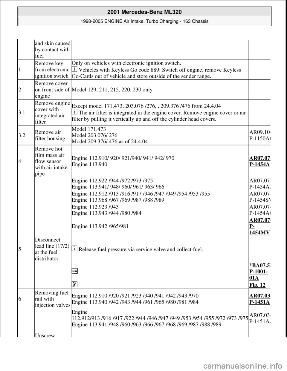
1
Remove key
from electronic
ignition switchOnly on vehicles with electronic ignition switch.
Vehicles with Keyless Go code 889: Switch off engine, remove Keyless
Go-Cards out of vehicle and store outside of the sender range.
2
Remove cover
on front side of
engine
Model 129, 211, 215, 220, 230 only
3.1
Remove engine
cover with
integrated air
filterExcept model 171.473, 203.076 /276, , 209.376 /476 from 24.4.04
The air filter is integrated in the engine cover. Remove engine cover or air
filter by pulling it vertically up and off the cylinder head covers.
3.2Remove air
filter housingModel 171.473
Model 203.076/ 276
Model 209.376/ 476 as of 24.4.04AR09.10-
P-1150AC
4
Remove hot
film mass air
flow sensor
with air intake
pipe
Engine 112.910/ 920/ 921/940/ 941/ 942/ 970
Engine 113.940AR07.07-
P-1454A
Engine 112.922 /944 /972 /973 /975
Engine 113.941/ 948/ 960/ 961/ 963/ 966AR07.07-
P-1454AA
Engine 112.912 /913 /916 /917 /946 /947 /949 /954 /953 /955
Engine 113.968 /967 /969 /987 /988 /989AR07.07-
P-1454SV
Engine 112.923 /943
Engine 113.943 /944 /980 /984AR07.07-
P-1454AG
Engine 113.942 /965/981
AR07.07-
P-
1454MV
5
Disconnect
lead line (17/2)
at the fuel
distributor
Release fuel pressure via service valve and collect fuel.
*BA07.52
P-1001-
01A
Fig. 12
6
Removing fuel
rail with
injection valvesEngine 112.910 /920 /921 /923 /940 /941 /942 /943 /970
Engine 113.940 /942 /943 /944 /961 /965 /980 /981 /984AR07.03-
P-1451A
Engine
112.912/913 /916 /917 /922 /944 /946 /947 /949 /953 /954 /955 /972 /973 /975
Engine 113.941 /948 /960 /963 /966 /967 /968 /969 /987 /988 /989AR07.03-
P-1451AA
Unscrew
2001 Mercedes-Benz ML320
1998-2005 ENGINE Air Intake, Turbo Charging - 163 Chassis
me
Saturday, October 02, 2010 3:16:57 PMPage 11 © 2006 Mitchell Repair Information Company, LLC.
Page 1201 of 4133
Shift-Lock, Function
See SHIFT
-LOCK FUNCTION.
Park Pawl Interlock, Function
See PARK PAWL INTERLOCK, FUNCTION
.
Steering Lock Interlock, Function
See STEERING LOCK INTERLOCK, FUNCTION
.
Survey Of System Components, Automatic Transmission, Location/Task/Design/Function
See SURVEY OF SYSTEM COMPONENTS, AUTOMATIC TRANSMISSION,
LOCATION/TASK/DESIGN/FUNCTION.
Automatic Transmission, Function
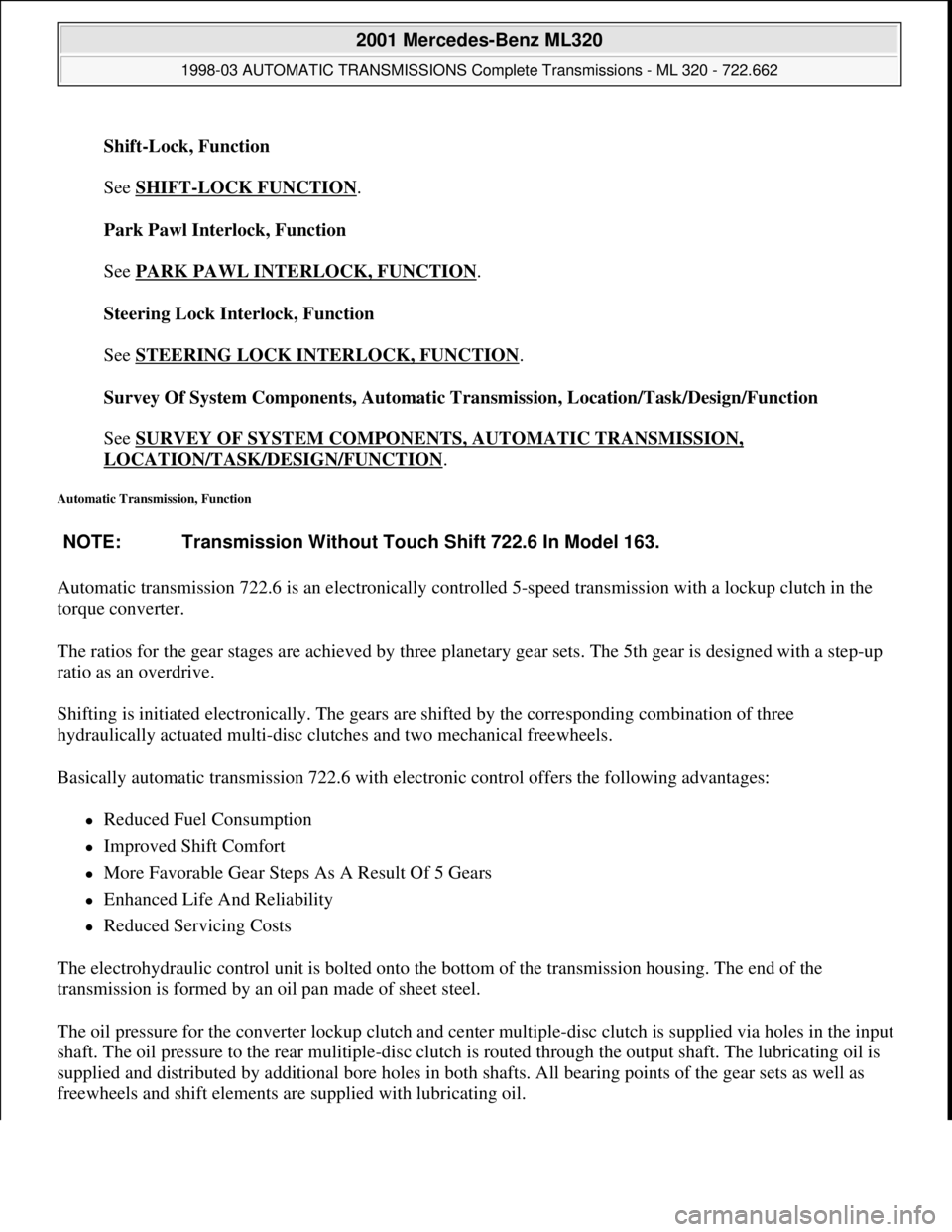
Automatic transmission 722.6 is an electronically controlled 5-speed transmission with a lockup clutch in the
torque converter.
The ratios for the gear stages are achieved by three planetary gear sets. The 5th gear is designed with a step-up
ratio as an overdrive.
Shifting is initiated electronically. The gears are shifted by the corresponding combination of three
hydraulically actuated multi-disc clutches and two mechanical freewheels.
Basically automatic transmission 722.6 with electronic control offers the following advantages:
Reduced Fuel Consumption
Improved Shift Comfort
More Favorable Gear Steps As A Result Of 5 Gears
Enhanced Life And Reliability
Reduced Servicing Costs
The electrohydraulic control unit is bolted onto the bottom of the transmission housing. The end of the
transmission is formed by an oil pan made of sheet steel.
The oil pressure for the converter lockup clutch and center multiple-disc clutch is supplied via holes in the input
shaft. The oil pressure to the rear mulitiple-disc clutch is routed through the output shaft. The lubricating oil is
supplied and distributed by additional bore holes in both shafts. All bearing points of the gear sets as well as
freewheels and shift elements are supplied with lubricatin
g oil. NOTE: Transmission Without Touch Shift 722.6 In Model 163.
2001 Mercedes-Benz ML320
1998-03 AUTOMATIC TRANSMISSIONS Complete Transmissions - ML 320 - 722.662
me
Saturday, October 02, 2010 3:15:25 PMPage 32 © 2006 Mitchell Repair Information Company, LLC.
Page 1352 of 4133
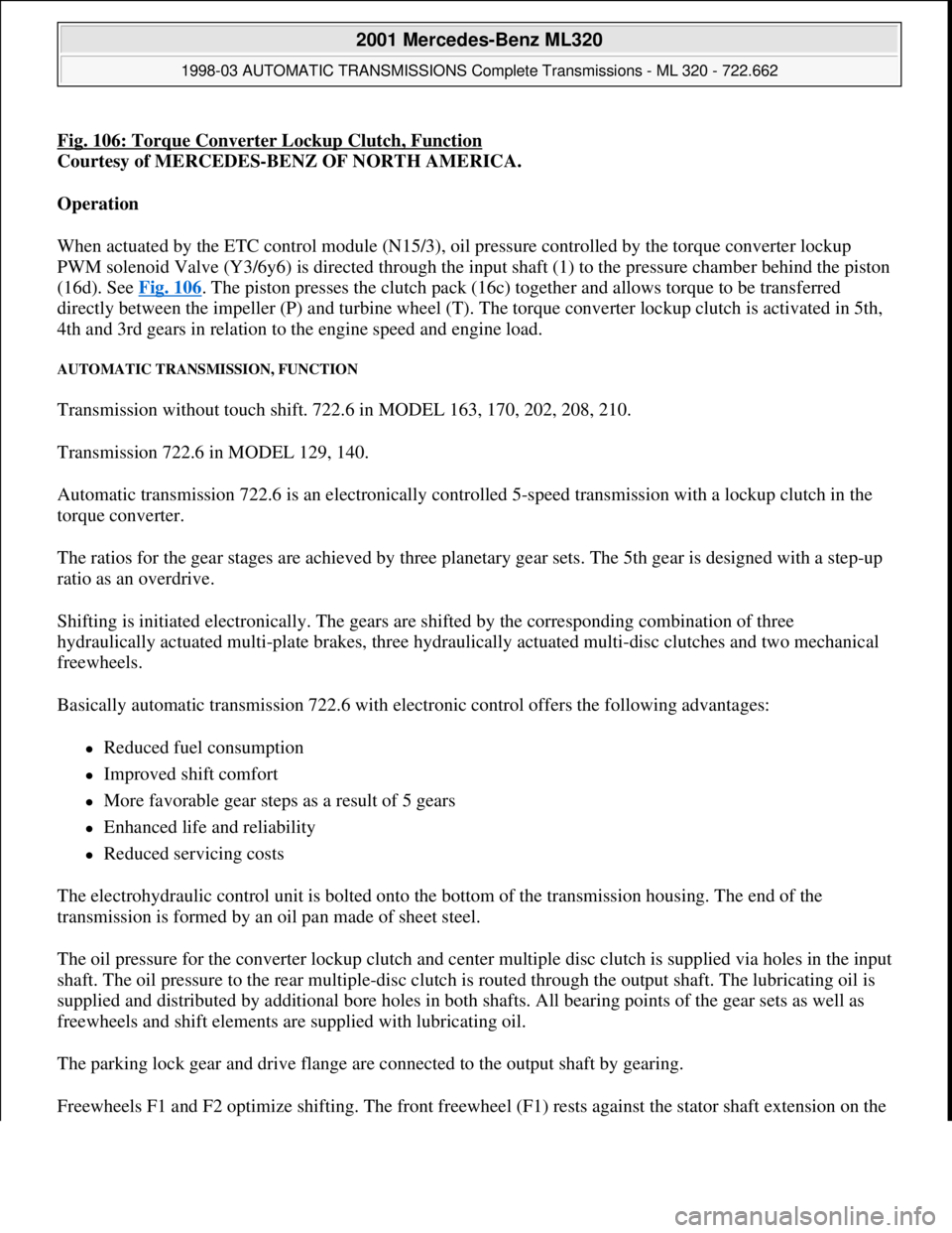
Fig. 106: Torque Converter Lockup Clutch, Function
Courtesy of MERCEDES-BENZ OF NORTH AMERICA.
Operation
When actuated by the ETC control module (N15/3), oil pressure controlled by the torque converter lockup
PWM solenoid Valve (Y3/6y6) is directed through the input shaft (1) to the pressure chamber behind the piston
(16d). See Fig. 106
. The piston presses the clutch pack (16c) together and allows torque to be transferred
directly between the impeller (P) and turbine wheel (T). The torque converter lockup clutch is activated in 5th,
4th and 3rd gears in relation to the engine speed and engine load.
AUTOMATIC TRANSMISSION, FUNCTION
Transmission without touch shift. 722.6 in MODEL 163, 170, 202, 208, 210.
Transmission 722.6 in MODEL 129, 140.
Automatic transmission 722.6 is an electronically controlled 5-speed transmission with a lockup clutch in the
torque converter.
The ratios for the gear stages are achieved by three planetary gear sets. The 5th gear is designed with a step-up
ratio as an overdrive.
Shifting is initiated electronically. The gears are shifted by the corresponding combination of three
hydraulically actuated multi-plate brakes, three hydraulically actuated multi-disc clutches and two mechanical
freewheels.
Basically automatic transmission 722.6 with electronic control offers the following advantages:
Reduced fuel consumption
Improved shift comfort
More favorable gear steps as a result of 5 gears
Enhanced life and reliability
Reduced servicing costs
The electrohydraulic control unit is bolted onto the bottom of the transmission housing. The end of the
transmission is formed by an oil pan made of sheet steel.
The oil pressure for the converter lockup clutch and center multiple disc clutch is supplied via holes in the input
shaft. The oil pressure to the rear multiple-disc clutch is routed through the output shaft. The lubricating oil is
supplied and distributed by additional bore holes in both shafts. All bearing points of the gear sets as well as
freewheels and shift elements are supplied with lubricating oil.
The parking lock gear and drive flange are connected to the output shaft by gearing.
Freewheels F1 and F2 optimize shiftin
g. The front freewheel (F1) rests against the stator shaft extension on the
2001 Mercedes-Benz ML320
1998-03 AUTOMATIC TRANSMISSIONS Complete Transmissions - ML 320 - 722.662
me
Saturday, October 02, 2010 3:15:28 PMPage 183 © 2006 Mitchell Repair Information Company, LLC.
Page 1358 of 4133
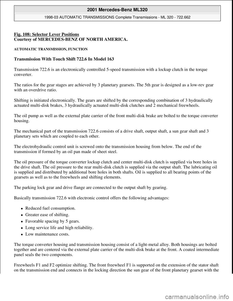
Fig. 108: Selector Lever Positions
Courtesy of MERCEDES-BENZ OF NORTH AMERICA.
AUTOMATIC TRANSMISSION, FUNCTION
Transmission With Touch Shift 722.6 In Model 163
Transmission 722.6 is an electronically controlled 5-speed transmission with a lockup clutch in the torque
converter.
The ratios for the gear stages are achieved by 3 planetary gearsets. The 5th gear is designed as a low-rev gear
with an overdrive ratio.
Shifting is initiated electronically. The gears are shifted by the corresponding combination of 3 hydraulically
actuated multi-disk brakes, 3 hydraulically actuated multi-disk clutches and 2 mechanical freewheels.
The oil pump as well as the external plate carrier of the front multi-disk brake are bolted to the torque converter
housing.
The mechanical part of the transmission 722.6 consists of a drive shaft, output shaft, a sun gear shaft and 3
planetary sets which are coupled to each other.
The electrohydraulic control unit is screwed onto the transmission housing from below. The end of the
transmission if formed by an oil pan made of sheet steel.
The oil pressure of the torque converter lockup clutch and center multi-disk clutch is supplied via bore holes in
the drive shaft. The oil pressure to the rear multi-disk clutch is supplied via the output shaft. The lubricating oil
is supplied and distributed by additional bore holes in both shafts. Oil is supplied to all bearing points of the
gearsets as well as to the freewheels and shifting elements.
The parking lock gear and drive flange are connected to the output shaft by gearing.
Basically transmission 722.6 with electronic control offers the following advantages:
Reduced fuel consumption.
Greater ease of shifting.
Favorable spacing by 5 gears.
Long service life and high reliability.
Low maintenance costs.
The torque converter housing and transmission housing consist of a light-metal alloy. Both housings are bolted
together and are centered via the external plate carrier of the multi-disk brake at the front. A coated intermediate
panel seals the two components.
Freewheels F1 and F2 optimize shifting. The front freewheel F1 is supported on the extension of the stator shaft
on the transmission end and connects in the lockin
g direction the sun gear of the front planetary gearset with the
2001 Mercedes-Benz ML320
1998-03 AUTOMATIC TRANSMISSIONS Complete Transmissions - ML 320 - 722.662
me
Saturday, October 02, 2010 3:15:28 PMPage 189 © 2006 Mitchell Repair Information Company, LLC.
Page 1452 of 4133
The aim of using the torque converter lockup clutch is to reduce the fuel consumption and exhaust gas
emissions of the vehicle by reducing torque converter slip. See Fig. 159
. This stands in contradiction to the ride
comfort demands made on the drive train with regard to its vibration behavior. The task of the electronic
transmission control is therefore to close the clutch in all driving situations relevant to fuel consumption, if
possible, and ensure that the engine vibrations are isolated from the drive train.
The characteristic curves shown in the diagram illustrate the different operating states of the torque converter
lockup clutch in relation to the accelerator pedal position and transmission output speed, plotted for one
transmission gear.
In addition to the evaluation of these characteristics, the status of the torque converter lockup clutch is also
determined by other variables.
Variables influencing the states of the torque converter lockup clutch:
Accelerator Pedal Movement
Uphill And Down Hill Gradients
Transmission Shift Functions
ATF Temperature
Durability Requirements
Load Condition
Engine Control Influences
Torque Converter Lockup Clutch Control Pressure, Function
See TORQUE CONVERTER LOCKUP CLUTCH CONTROL PRESSURE, FUNCTION
.
Torque Converter Lockup Clutch Control Pressure, Function
Apart from extreme states of open or closed, it is possible to operate the torque converter lockup clutch with
preset slip speeds. To enable this variable control pressure must be applied to the torque converter lockup clutch
regulating valve.
The torque converter lockup clutch control pressure is adapted to each operating state via the pulse-width
modulated torque converter lockup solenoid valve (Y3/6y6) which is actuated by the ETC control unit (N15/3).
Torque Converter Lockup Clutch PWM Solenoid Valve, Location/Task/Design/Function
See LOCATION/TASK/DESIGN/FUNCTION OF PWM SOLENOID VALVE, TORQUE
CONVERTER LOCKUP CLUTCH.
Torque Converter Lockup Clutch, Location/Task/Design/Function
See TORQUE CONVERTER LOCK
-UP CLUTCH, LOCATION/TASK/DESIGN/FUNCTION.
Torque Converter Lockup Clutch Regulating Valve, Location/Task/Function
2001 Mercedes-Benz ML320
1998-03 AUTOMATIC TRANSMISSIONS Complete Transmissions - ML 320 - 722.662
me
Saturday, October 02, 2010 3:15:29 PMPage 283 © 2006 Mitchell Repair Information Company, LLC.
Page 1465 of 4133
The aim of using the torque converter lockup clutch is to reduce the fuel consumption and exhaust gas
emissions of the vehicle by reducing torque converter slip. See Fig. 165
. This stands in contradiction to the ride
comfort demands made on the drive train with regard to its vibration behavior. The task of the electronic
transmission control is therefore to close to the clutch in all driving situations relevant to fuel consumption, if
possible, and ensure that the engine vibrations are isolated from the drive train.
The characteristic curves shown in the diagram illustrate the different operating states of the torque converter
lockup clutch in relation to the accelerator pedal position and transmission output speed, plotted for one
transmission gear.
In addition to the evaluation of these characteristics, the status of the torque converter lockup clutch is also
determined by other variables.
Variables influencing the states of the torque converter lockup clutch:
Accelerator Pedal Movement
Uphill And Down Hill Gradients
Transmission Shift Functions
ATF Temperature
Durability Requirements
Load Condition
Engine Control Influences
Torque Converter Lockup Clutch Control Pressure, Function
See TORQUE CONVERTER LOCKUP CLUTCH CONTROL PRESSURE, FUNCTION
.
REMOVE/INSTALL TRANSFER CASE
Remove/Install
2001 Mercedes-Benz ML320
1998-03 AUTOMATIC TRANSMISSIONS Complete Transmissions - ML 320 - 722.662
me
Saturday, October 02, 2010 3:15:30 PMPage 296 © 2006 Mitchell Repair Information Company, LLC.
Page 1471 of 4133
Basically automatic transmission 722.6 with electronic control offers the following advantages:
Reduced Fuel Consumption
Improved Shift Comfort
More Favorable Gear Steps As A Result Of 5 Gears
Enhanced Life And Reliability
Reduced Servicing Costs
The electrohydraulic control unit is bolted onto the bottom of the transmission housing. The end of the
transmission is formed by an oil pan made of sheet steel.
The oil pressure for the converter lockup clutch and center multiple-disc clutch is supplied via holes in the input
shaft. The oil pressure to the rear multiple-disc clutch is routed through the output shaft. The lubricating oil is
supplied and distributed by additional bore holes in both shafts. All bearing points of the gear sets as well as
freewheels and shift elements are supplied with lubricating oil.
The parking lock gear and drive flange are connected to the output shaft by gearing.
Freewheels F1 and F2 optimize shifting. The front freewheel (F1) rests against the stator shaft extension on the
transmission side and connects the sun gear of the front planetary gear set to the transmission housing in the
locking direction.
The torque converter housing and transmission housing are made of a metal alloy. They are bolted together and
centered via the outer multiple-disc carrier of the multiple-disc brake B1. A coated intermediate panel seals the
two components.
The oil pump and outer multiple-disc carrier of the front multiple-disc brake are bolted to the converter housing.
The mechanical part consists of the propeller shaft, output shaft, a sun gear shaft and three planetary gearsets
which are coupled together.
In transmissions for powerful engines, the planetary gearsets have 4 planetary gears, while for less powerful
engines the front and rear planetary gear system has three planetary gear wheels. The stator shaft is pressed into
this and is secured against turning by a spline.
The rear freewheel F2 connects the sun gear of the center planetary gear set to the sun gear of the rear planetary
gearset in the locking direction.
The electrohydraulic control unit consists of the shift plate made of light alloy for hydraulic control and an
electronic control unit.
The electrical control unit consists of a supporting body made of plastic in which the electrical components are
combined. The shell is screwed to the shift plate. Conductor tracks which are integrated into the shell, connect
the electric components to a plug connector. This 13-pin plug connector forms the connection with the vehicle-
side wiring harness and with the ETC 5 (electronic transmission control) control module (N15/5) via a bayonet
lock.
2001 Mercedes-Benz ML320
1998-03 AUTOMATIC TRANSMISSIONS Complete Transmissions - ML 320 - 722.662
me
Saturday, October 02, 2010 3:15:30 PMPage 302 © 2006 Mitchell Repair Information Company, LLC.
Page 1819 of 4133
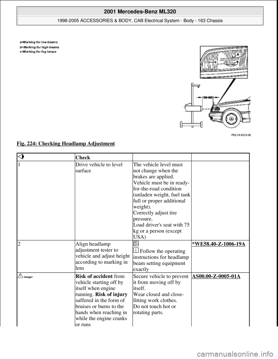
Fig. 224: Checking Headlamp Adjustment
Check
1Drive vehicle to level
surfaceThe vehicle level must
not change when the
brakes are applied.
Vehicle must be in ready-
for-the-road condition
(unladen weight, fuel tank
full or proper additional
weight).
Correctly adjust tire
pressure.
Load driver's seat with 75
kg or a person (except
USA)
2Align headlamp
adjustment tester to
vehicle and adjust height
according to marking in
lens
Follow the operating
instructions for headlamp
beam setting equipment
exactly*WE58.40-Z-1006-19A
Risk of accident from
vehicle starting off by
itself when engine
running. Risk of injury
suffered in the form of
bruises or burns to the
hands when reaching in
while the engine cranks
or runsSecure vehicle to prevent
it from moving off by
itself.
Wear closed and close-
fitting work clothes.
Do not touch hot or
rotating parts.AS00.00-Z-0005-01A
2001 Mercedes-Benz ML320
1998-2005 ACCESSORIES & BODY, CAB Electrical System - Body - 163 Chassis
me
Saturday, October 02, 2010 3:30:10 PMPage 324 © 2006 Mitchell Repair Information Company, LLC.