1997 MERCEDES-BENZ ML320 fuel pressure
[x] Cancel search: fuel pressurePage 2357 of 4133
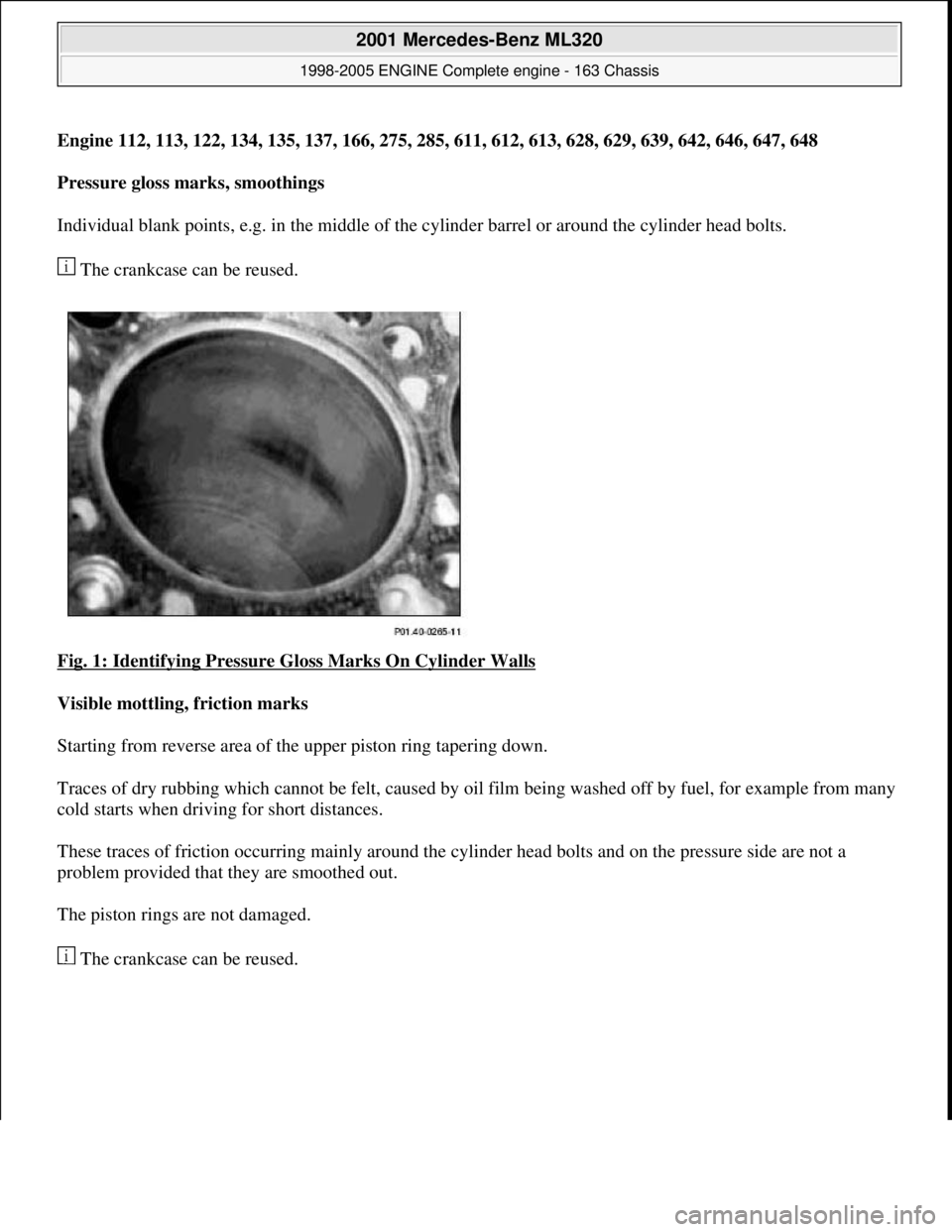
Engine 112, 113, 122, 134, 135, 137, 166, 275, 285, 611, 612, 613, 628, 629, 639, 642, 646, 647, 648
Pressure gloss marks, smoothings
Individual blank points, e.g. in the middle of th e cylinder barrel or around the cylinder head bolts.
The crankcase can be reused.
Fig. 1: Identifying Pressure Gloss Marks On Cylinder Walls
Visible mottling, friction marks
Starting from reverse area of th e upper piston ring tapering down.
Traces of dry rubbing which cannot be felt, caused by oi l film being washed off by fuel, for example from many
cold starts when driving for short distances.
These traces of friction occurring mainly around the cy linder head bolts and on the pressure side are not a
problem provided that they are smoothed out.
The piston rings are not damaged.
The crankcase can be reused.
2001 Mercedes-Benz ML320
1998-2005 ENGINE Complete engine - 163 Chassis
me
Saturday, October 02, 2010 3:17:55 PMPage 2 © 2006 Mitchell Repair Information Company, LLC.
Page 2363 of 4133
Determine loss of pressure
at cylinderENGINE all
AH01.00-
N-1300-
02A
Notes for position of
engine numberENGINE 155AH01.00-P-
0001-01A
Notes for position of
engine numberENGINE 166, 266, 640, 668AH01.00-P-
0001-01B
Notes for position of
engine numberENGINE 611, 612, 613, 646, 647, 648AH01.00-P-
0001-01C
Notes for position of
engine numberENGINE 112, 113, 120, 137, 271, 272, 273, 275, 285, 628,
629, 642AH01.00-P-
0001-01D
Notes for position of
engine numberENGINE 601, 602, 603, 604, 605, 606AH01.00-P-
0001-01E
Notes for position of
engine numberENGINE 122.9, 134.9, 135.9, 639.9 in MODEL 454.0AH01.00-P-
0001-01FF
Notes for position of
engine numberENGINE 160.910, 660.940 in MODEL 450.3 /4AH01.00-P-
0001-01SM
General information on
inspecting cylinder wallsENGINE 156
AH01.00-P-
0300-
01AMG
Determining pressure loss
of cylindersENGINE 640AH01.00-P-
1300-02AL
Use of engine no. when
installing reconditioned
engines and factory-new
replacement engines or
crankcases
ENGINE allAH01.10-P-
0001-01A
Use of unleaded fuel in
reconditioned enginesENGINE 102, 110, 115, 116, 117...AH01.10-P-
1000-01A
Bolt diagram cylinder head
coverENGINE 120AH01.20-P-
5014-04AO
Notes on application of
sealant to cylinder shutoff
oil pump
ENGINE 137.970AH01.30-P-
1000-01A
Notes on application of
sealant to front cover at
cylinder head
ENGINE 668.914/940/941 /942AH01.30-P-
1000-02A
Notes on application of
sealant to front cover of the
cylinder head
ENGINE 640 in MODEL 169, 245AH01.30-P-
1000-02AL
Notes on application of
sealant to front cover at
cylinder head
ENGINE 275AH01.30-P-
1000-02C
Notes on application of
sealing compound to front ENGINE 275AH01.30-P-
2001 Mercedes-Benz ML320
1998-2005 ENGINE Complete engine - 163 Chassis
me
Saturday, October 02, 2010 3:17:55 PMPage 7 © 2006 Mitchell Repair Information Company, LLC.
Page 2411 of 4133
housing coolant line
--> (17) from
thermostat housing
15.1Remove radiator Only engine 113.942 /965 /981.AR20.20-P-
3865HC
16Remove brake
pressure regulator
vacuum line (5) from
brake pressure
regulator at rear of
intake manifold
17Extract power
steering pump (19)
oil Hand pumpFig. 50
18Detach return flow
line and pressure line
of power steering
pump (19) Seal connections!
Set of plugsFig. 51
*BA46.30-P-
1002-01A
*BA46.30-P-
1003-01A
19Remove regeneration
vacuum line (6) from
intake pipe
Risk of explosion
caused by ignition of
flammable products,
risk of poisoning
caused by inhaling
fuel vapors or
swallowing fuel as
well as risk of
injury to skin and
eyes exposed to fuel.No fire, sparks, ope n flames or smoking.AS47.00-Z-0001-
01A
Pour fuels only into suitable and appropriately
marked containers.
Wear protective clothing when handling fuel.
20Disconnect fuel line
(4) Release fuel pressure through service valve!
Collect fuel.
M112: ?
*BA07.52-P-
1001-01A
M113: ?
*BA07.52-P-
1001-01A
Pressure hoseFig. 52
21Detach coolant line
(14)
2001 Mercedes-Benz ML320
1998-2005 ENGINE Complete engine - 163 Chassis
me
Saturday, October 02, 2010 3:17:56 PMPage 55 © 2006 Mitchell Repair Information Company, LLC.
Page 2420 of 4133
Crankcase ventilation, cylinder head cover
Fuel rail
railvehicles with a non-
flexible fuel line.
Release fuel pressure
through service valve!
Pressure hoseFig. 52
*BA07.52-P-1001-01A
*BA07.52-P-1001-01A
11Remove cylinder head
covers (4, 5) *BA01.20-P-1001-01E
Installation:
Ensure cylinder head
cover gasket is correctly
installed.AR01.20-P-5014-01B
12Install in the reverse order
13Risk of accident caused by
vehicle starting off by itself
when engine is running.
Risk of injury caused by
contusions and burns during
starting procedure or when
working near the running
engine
Run engine and inspect for
leaksSecure vehicle to prevent
it from moving by itself.
Wear closed and snug-
fitting work clothes.
Do not grasp hot or
rotating parts.AS00.00-Z-0005-01A
NumberDesignation
Engine 112.910/911/
912/913/914/ 915/916/917/
920/921/922/ 923/940/941/
942/943/944/ 945/946/947/
949/951/953/ 954/955/960/
961/970/972/ 973/975/976Engines 113.940/
941/942/943/ 944/948/960/
961/962/963/ 964/965/966/
967/968/969/ 971/980/981/
982/984/986/ 992/995
Engine
113.987/988/
990/991/993
BA01.20-
P-1001-
01EScrew of
cylinder
head cover
Nm8108
BA01.20-
P-1002-
01E
Bolt of
ignition
coils to
cylinder
head cover
Nm888
NumberDesignationEngine 112 except
112.945/951/ 960/961Engine
112.945Engine
112.960/ 976Engine
112.960/ 961
AMG
2001 Mercedes-Benz ML320
1998-2005 ENGINE Complete engine - 163 Chassis
me
Saturday, October 02, 2010 3:17:56 PMPage 64 © 2006 Mitchell Repair Information Company, LLC.
Page 2424 of 4133
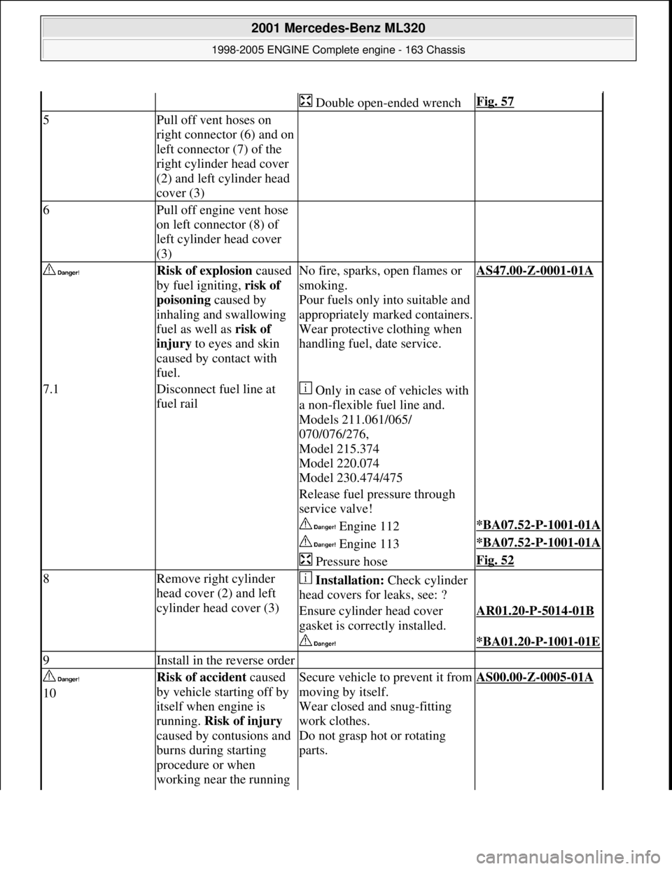
Double open-ended wrenchFig. 57
5Pull off vent hoses on
right connector (6) and on
left connector (7) of the
right cylinder head cover
(2) and left cylinder head
cover (3)
6Pull off engine vent hose
on left connector (8) of
left cylinder head cover
(3)
Risk of explosion caused
by fuel igniting, risk of
poisoning caused by
inhaling and swallowing
fuel as well as risk of
injury to eyes and skin
caused by contact with
fuel.No fire, sparks, open flames or
smoking.
Pour fuels only into suitable and
appropriately marked containers.
Wear protective clothing when
handling fuel, date service.AS47.00-Z-0001-01A
7.1Disconnect fuel line at
fuel rail Only in case of vehicles with
a non-flexible fuel line and.
Models 211.061/065/
070/076/276,
Model 215.374
Model 220.074
Model 230.474/475
Release fuel pr essure through
service valve!
Engine 112*BA07.52-P-1001-01A
Engine 113*BA07.52-P-1001-01A
Pressure hoseFig. 52
8Remove right cylinder
head cover (2) and left
cylinder head cover (3) Installation: Check cylinder
head covers for leaks, see: ?
Ensure cylinder head cover
gasket is correctly installed.AR01.20-P-5014-01B
*BA01.20-P-1001-01E
9Install in the reverse order
10Risk of accident caused
by vehicle starting off by
itself when engine is
running. Risk of injury
caused by contusions and
burns during starting
procedure or when
working near the running Secure vehicle to prevent it from
moving by itself.
Wear closed and snug-fitting
work clothes.
Do not grasp hot or rotating
parts.AS00.00-Z-0005-01A
2001 Mercedes-Benz ML320
1998-2005 ENGINE Complete engine - 163 Chassis
me
Saturday, October 02, 2010 3:17:56 PMPage 68 © 2006 Mitchell Repair Information Company, LLC.
Page 2442 of 4133
Engine 112 in model 208,
Engine 112, 113, 612.963, 628.963 in model
163,
Engines 112.923/943, 113.961 in model 129,
Engines 137, 275 in models 215, 220,
Engines 613.960, 628.960 in model 220,
Engine 113.992 in model 230.474,
Engine 271 in MODELS 209, 203,
Engine 285.950 in models 240.078 /178,
Engine 612.967 in model 209.316,
Engine 648 in model 220 Engine 112.951 in
model
639.601/603 /605 /701 /703 /705 /801 /803 /805
Engine 646.983 /984 in model
639. /605 /701 /703/705/801 /803/805
Engine 646.982 in model
639.601 /603 /605 /701 /703 /705
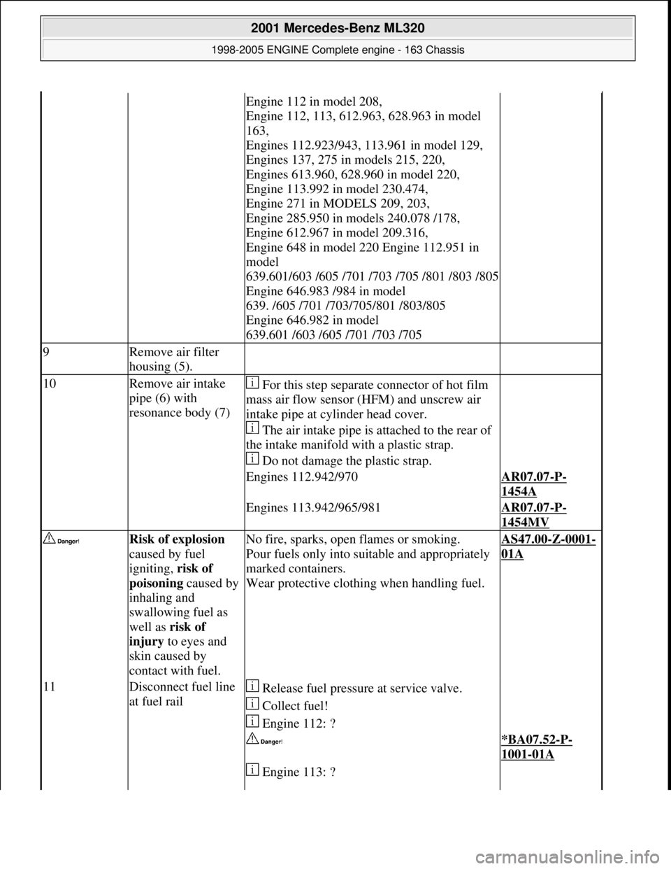
9Remove air filter
housing (5).
10Remove air intake
pipe (6) with
resonance body (7) For this step separate connector of hot film
mass air flow sensor (HFM) and unscrew air
intake pipe at cylinder head cover.
The air intake pipe is attached to the rear of
the intake manifold with a plastic strap.
Do not damage the plastic strap.
Engines 112.942/970AR07.07-P-
1454A
Engines 113.942/965/981AR07.07-P-
1454MV
Risk of explosion
caused by fuel
igniting, risk of
poisoning caused by
inhaling and
swallowing fuel as
well as risk of
injury to eyes and
skin caused by
contact with fuel.No fire, sparks, open flames or smoking.
Pour fuels only into suitable and appropriately
marked containers.
Wear protective clothing when handling fuel.AS47.00-Z-0001-
01A
11Disconnect fuel line
at fuel rail Release fuel pressure at service valve.
Collect fuel!
Engine 112: ?
*BA07.52-P-
1001-01A
Engine 113: ?
2001 Mercedes-Benz ML320
1998-2005 ENGINE Complete engine - 163 Chassis
me
Saturday, October 02, 2010 3:17:57 PMPage 86 © 2006 Mitchell Repair Information Company, LLC.
Page 2443 of 4133
*BA07.52-P-
1001-01A
Pressure hoseFig. 52
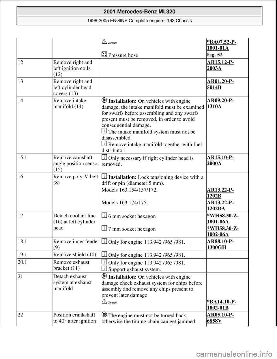
12Remove right and
left ignition coils
(12) AR15.12-P-
2003A
13Remove right and
left cylinder head
covers (13) AR01.20-P-
5014B
14Remove intake
manifold (14) Installation: On vehicles with engine
damage, the intake manifold must be examined
for swarfs before assembling and any swarfs
present must be removed, in order to avoid
consequential damage.
The intake manifold system must not be
disassembled.
Remove intake manifold together with fuel
distributor.AR09.20-P-
1310A
15.1Remove camshaft
angle position sensor
(15) Only necessary if right cylinder head is
removed.AR15.10-P-
2000A
16Remove poly-V-belt
(8) Installation: Lock tensioning device with a
drift or pin (diameter 5 mm).
Models 163.154/157/172.AR13.22-P-
1202B
Models 163.174/175.AR13.22-P-
1202BA
17Detach coolant line
(16) at left cylinder
head 6 mm socket hexagon*WH58.30-Z-
1001-06A
7 mm socket hexagon*WH58.30-Z-
1002-06A
18.1Remove inner fender
(9) Only for engine 113.942 /965 /981.AR88.10-P-
1300GH
19.1Remove shield (10) Only for engine 113.942 /965 /981.
20.1Remove exhaust
bracket (11) Only for engine 113.942 /965 /981.
Support exhaust system.
21Detach exhaust
system at exhaust
manifold Installation: On vehicles with engine
damage check exhaust sy stem for chips before
assembly and remove any chips present to
prevent later damage
*BA14.10-P-
1002-01B
22Position crankshaft
to 40° after ignition The engine must not be turned back;
otherwise the timing chain can get jammed. AR05.10-P-
6858V
2001 Mercedes-Benz ML320
1998-2005 ENGINE Complete engine - 163 Chassis
me
Saturday, October 02, 2010 3:17:57 PMPage 87 © 2006 Mitchell Repair Information Company, LLC.
Page 2583 of 4133
AR07.16-P-1100MM
Remove, install fuel cooler
5.11.99
ENGINE
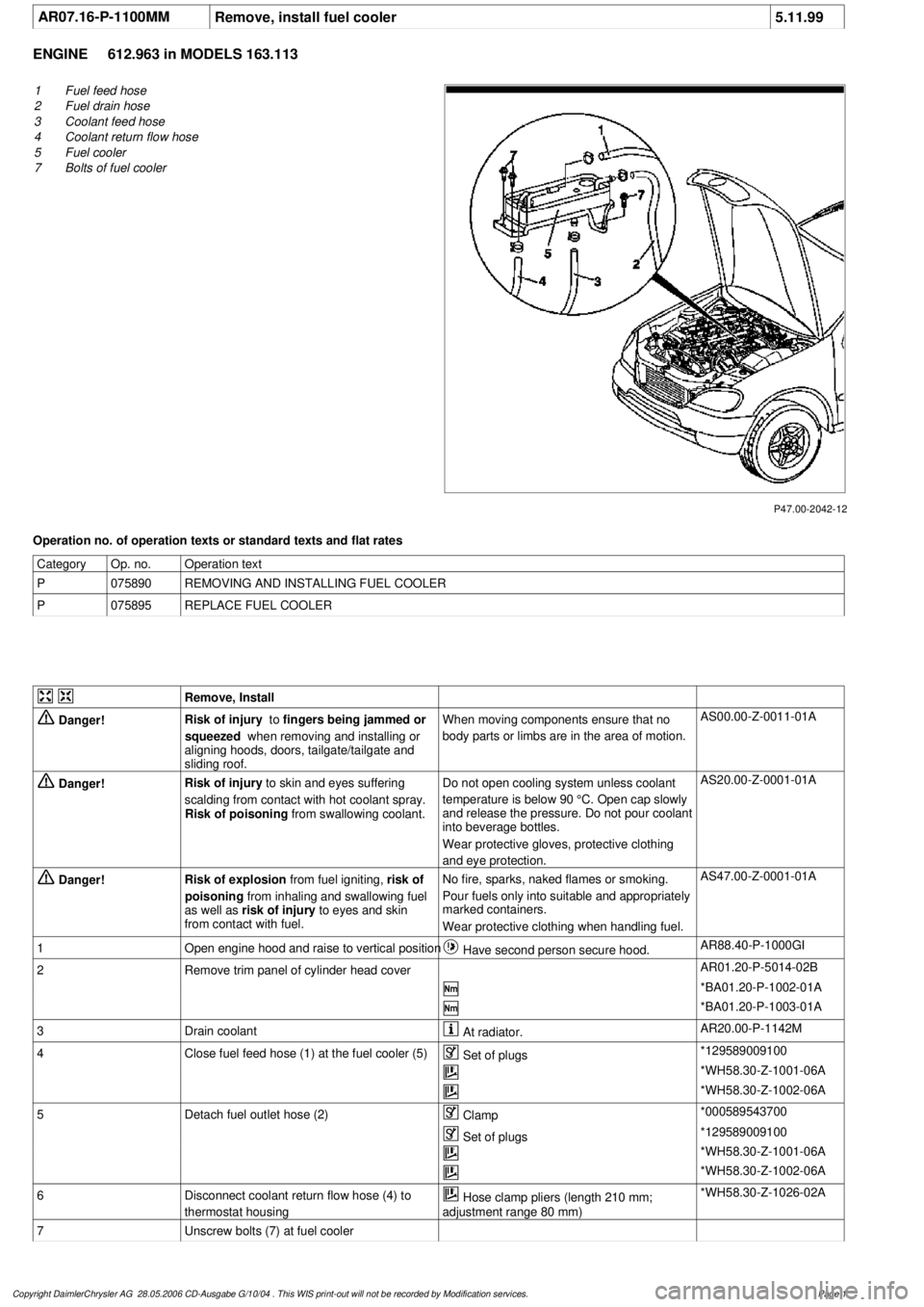
612.963 in MODELS 163.113
P47.00-2042-12
1
Fuel feed hose
2
Fuel drain hose
3
Coolant feed hose
4
Coolant return flow hose
5
Fuel cooler
7
Bolts of fuel cooler
Operation no. of operation texts or standard texts and flat rates
Category
Op. no.
Operation text
P
075890
REMOVING AND INSTALLING FUEL COOLER
P
075895
REPLACE FUEL COOLER
Remove, Install
Danger!
Risk of injury
to
fingers being jammed or
squeezed
when removing and installing or
aligning hoods, doors, tailgate/tailgate and
sliding roof.
When moving components ensure that no
body parts or limbs are in the area of motion.
AS00.00-Z-0011-01A
Danger!
Risk of injury
to skin and eyes suffering
scalding from contact with hot coolant spray.
Risk of poisoning
from swallowing coolant.
Do not open cooling system unless coolant
temperature is below 90 °C. Open cap slowly
and release the pressure. Do not pour coolant
into beverage bottles.
Wear protective gloves, protective clothing
and eye protection.
AS20.00-Z-0001-01A
Danger!
Risk of explosion
from fuel igniting,
risk of
poisoning
from inhaling and swallowing fuel
as well as
risk of injury
to eyes and skin
from contact with fuel.
No fire, sparks, naked flames or smoking.
Pour fuels only into suitable and appropriately
marked containers.
Wear protective clothing when handling fuel.
AS47.00-Z-0001-01A
1
Open engine hood and raise to vertical position
Have second person secure hood.
AR88.40-P-1000GI
2
Remove trim panel of cylinder head cover
AR01.20-P-5014-02B
*BA01.20-P-1002-01A
*BA01.20-P-1003-01A
3
Drain coolant
At radiator.
AR20.00-P-1142M
4
Close fuel feed hose (1) at the fuel cooler (5)
Set of plugs
*129589009100
*WH58.30-Z-1001-06A
*WH58.30-Z-1002-06A
5
Detach fuel outlet hose (2)
Clamp
*000589543700
Set of plugs
*129589009100
*WH58.30-Z-1001-06A
*WH58.30-Z-1002-06A
6
Disconnect coolant return flow hose (4) to
thermostat housing
Hose clamp pliers (length 210 mm;
adjustment range 80 mm)
*WH58.30-Z-1026-02A
7
Unscrew bolts (7) at fuel cooler
Copyright DaimlerChrysler AG 28.05.2006 CD-Ausgabe G/10/04 . This WIS print-out will not be recorde
d by Modification services.
Page 1