Page 3561 of 4133
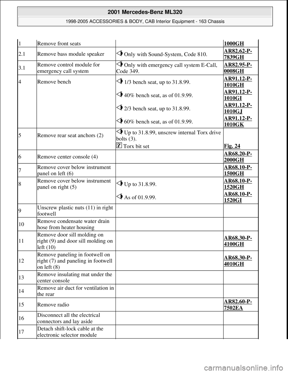
1Remove front seats 1000GH
2.1Remove bass module speaker Only with Sound-System, Code 810.AR82.62-P-
7839GH
3.1Remove control module for
emergency call system Only with emergency call system E-Call,
Code 349.AR82.95-P-
0008GH
4Remove bench 1/3 bench seat, up to 31.8.99.AR91.12-P-
1010GH
40% bench seat, as of 01.9.99.AR91.12-P-
1010GI
2/3 bench seat, up to 31.8.99.AR91.12-P-
1010GJ
60% bench seat, as of 01.9.99.AR91.12-P-
1010GK
5Remove rear seat anchors (2) Up to 31.8.99, unscrew internal Torx drive
bolts (3).
Torx bit setFig. 24
6Remove center console (4) AR68.20-P-
2000GH
7Remove cover below instrument
panel on left (6) AR68.10-P-
1500GH
8Remove cover below instrument
panel on right (5) Up to 31.8.99.AR68.10-P-
1520GH
As of 01.9.99.AR68.10-P-
1520GI
9Unscrew plastic nuts (11) in right
footwell
10Remove condensate water drain
hose from heater housing
11
Remove door sill molding on
right (9) and door sill molding on
left (10)
AR68.30-P-
4100GH
12
Remove paneling in footwell on
right (7) and paneling in footwell
on left (8)
AR68.30-P-
4010GH
13Remove insulating mat under the
center console
14Remove air duct for ventilation in
the rear
15Remove radio AR82.60-P-
7502EA
16Disconnect all the electrical
connectors and lay aside
17Detach shift-lock cable at the
electronic selector module
2001 Mercedes-Benz ML320
1998-2005 ACCESSORIES & BODY, CAB Interior Equipment - 163 Chassis
me
Saturday, October 02, 2010 3:35:22 PMPage 43 © 2006 Mitchell Repair Information Company, LLC.
Page 3562 of 4133
Instrument panel
Fig. 40: Identifying Torx Bit Set (000 589 01 10 00)
DISASSEMBLING AND ASSEMBLING CENTER CONSOLE - AR68.20-P-2150GH
MODEL 163.113 /136 /154 /172 /174 up to 31.8.01
18
Remove bracket between
instrument panel center part and
transmission tunnel
*BA68.10-P-
1003-01A
19Pull out floor covering (1) in area
of C-pillar and remove
Do not damage electrical leads.
Installation: Align floor covering at
attachment points for seats and thread electric
wires through corresponding cutouts.
20Install in the reverse order
NumberDesignationMODEL Series 163
BA68.10-P-1003-01AScrew, dashboard to transmission tunnelNm30
2001 Mercedes-Benz ML320
1998-2005 ACCESSORIES & BODY, CAB Interior Equipment - 163 Chassis
me
Saturday, October 02, 2010 3:35:22 PMPage 44 © 2006 Mitchell Repair Information Company, LLC.
Page 3575 of 4133
Safety belts/emergency tensioning retractors
Luggage nets
Child seats
Fig. 57: Identifying Assembly Wedge (110 589 03 59 00)
Fig. 58: Identifying Torx Bit Set (000 589 01 10 00)
REMOVE/INSTALL PANELING IN FOOTWELL - AR68.30-P-4010GH
MODELS 163.113 /128 /136 /154 /157 /172 /174 /175
rear-end door.
8Remove floor covering (3) to rear Installation: Install floor covering
below side paneling.
Assembly wedgeFig. 57
9Install in the reverse order
NumberDesignationModel 163 up to 08/99Model 163 as of 09/99
BA91.40-P-1001-01DBelt end fitting screwNm3535
NumberDesignationModel Series
163
BA68.50-P-1001-
02ABolt securing cargo retainer br acket to loading compartment
floorNm24
NumberDesignationModel Series 163
BA91.20-P-1001-01ABracket for child seat anchorage on load compartment floorNm24
2001 Mercedes-Benz ML320
1998-2005 ACCESSORIES & BODY, CAB In terior Equipment - 163 Chassis
me
Saturday, October 02, 2010 3:35:22 PMPage 57 © 2006 Mitchell Repair Information Company, LLC.
Page 3583 of 4133
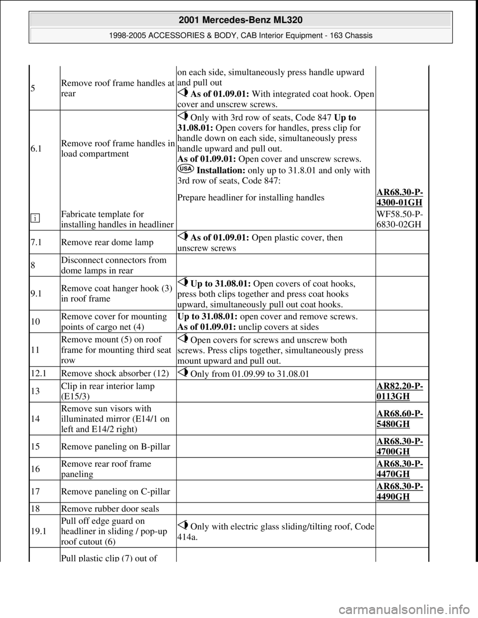
5Remove roof frame handles at
rear
on each side, simultaneously press handle upward
and pull out
As of 01.09.01:With integrated coat hook. Open
cover and unscrew screws.
6.1Remove roof frame handles in
load compartment
Only with 3rd row of seats, Code 847 Up to
31.08.01: Open covers for handles, press clip for
handle down on each side, simultaneously press
handle upward and pull out.
As of 01.09.01: Open cover and unscrew screws.
Installation: only up to 31.8.01 and only with
3rd row of seats, Code 847:
Prepare headliner for installing handlesAR68.30-P-
4300-01GH
Fabricate template for
installing handles in headliner WF58.50-P-
6830-02GH
7.1Remove rear dome lamp As of 01.09.01: Open plastic cover, then
unscrew screws
8Disconnect connectors from
dome lamps in rear
9.1Remove coat hanger hook (3)
in roof frame Up to 31.08.01: Open covers of coat hooks,
press both clips together and press coat hooks
upward, simultaneously pull out coat hooks.
10Remove cover for mounting
points of cargo net (4)Up to 31.08.01: open cover and remove screws.
As of 01.09.01: unclip covers at sides
11
Remove mount (5) on roof
frame for mounting third seat
row Open covers for screws and unscrew both
screws. Press clips together, simultaneously press
mount upward and pull out.
12.1Remove shock absorber (12) Only from 01.09.99 to 31.08.01
13Clip in rear interior lamp
(E15/3) AR82.20-P-
0113GH
14
Remove sun visors with
illuminated mirror (E14/1 on
left and E14/2 right)
AR68.60-P-
5480GH
15Remove paneling on B-pillar AR68.30-P-
4700GH
16Remove rear roof frame
paneling AR68.30-P-
4470GH
17Remove paneling on C-pillar AR68.30-P-
4490GH
18Remove rubber door seals
19.1
Pull off edge guard on
headliner in sliding / pop-up
roof cutout (6) Only with electric glass sliding/tilting roof, Code
414a.
Pull plastic clip (7) out of
2001 Mercedes-Benz ML320
1998-2005 ACCESSORIES & BODY, CAB Interior Equipment - 163 Chassis
me
Saturday, October 02, 2010 3:35:22 PMPage 65 © 2006 Mitchell Repair Information Company, LLC.
Page 3782 of 4133
AZ91.20-P-0001A
Retrofitting anchor rings for child seat restraint attachments
14.11.00
MODEL
163.113 /136 /154 /172 /174
P91.20-2039-06
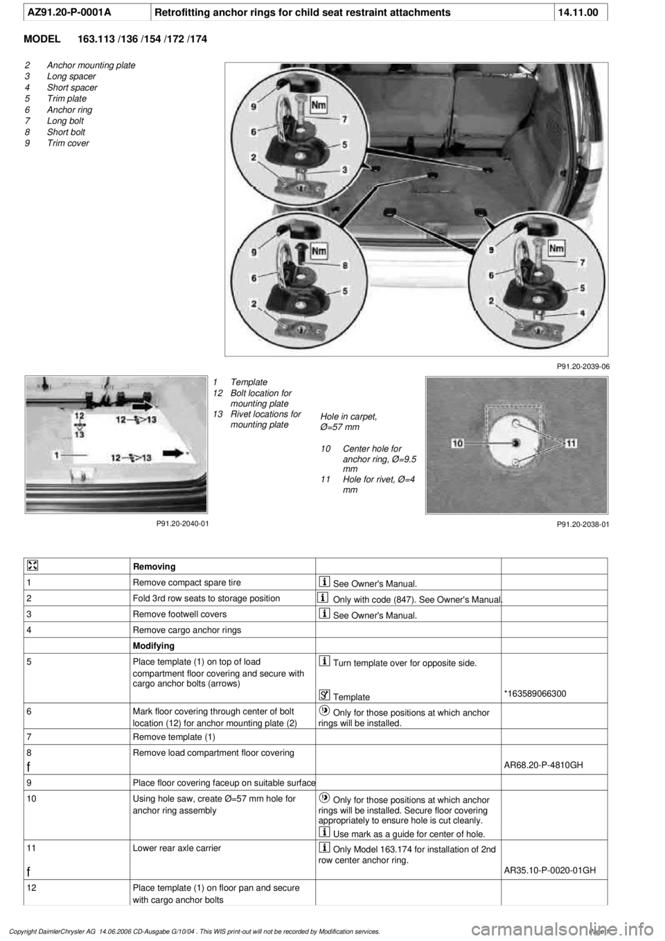
2
Anchor mounting plate
3
Long spacer
4
Short spacer
5
Trim plate
6
Anchor ring
7
Long bolt
8
Short bolt
9
Trim cover
P91.20-2040-01
1
Template
12
Bolt location for
mounting plate
13
Rivet locations for
mounting plate
Hole in carpet,
Ø=57 mm
10
Center hole for
anchor ring, Ø=9.5
mm
11
Hole for rivet, Ø=4
mm
P91.20-2038-01
Removing
1
Remove compact spare tire
See Owner's Manual.
2
Fold 3rd row seats to storage position
Only with code (847). See Owner's Manual.
3
Remove footwell covers
See Owner's Manual.
4
Remove cargo anchor rings
Modifying
5
Place template (1) on top of load
compartment floor covering and secure with
cargo anchor bolts (arrows)
Turn template over for opposite side.
Template
*163589066300
6
Mark floor covering through center of bolt
location (12) for anchor mounting plate (2)
Only for those positions at which anchor
rings will be installed.
7
Remove template (1)
8
Remove load compartment floor covering
f
AR68.20-P-4810GH
9
Place floor covering faceup on suitable surface
10
Using hole saw, create Ø=57 mm hole for
anchor ring assembly
Only for those positions at which anchor
rings will be installed. Secure floor covering
appropriately to ensure hole is cut cleanly.
Use mark as a guide for center of hole.
11
Lower rear axle carrier
Only Model 163.174 for installation of 2nd
row center anchor ring.
f
AR35.10-P-0020-01GH
12
Place template (1) on floor pan and secure
with cargo anchor bolts
Copyright DaimlerChrysler AG 14.06.2006 CD-Ausgabe G/10/04 . This WIS print-out will not be recorde
d by Modification services.
Page 1
Page 3789 of 4133
AR91.29-P-0008GH
Remove/install seat adjustment control module
23.6.99
MODEL
163.113 /128,
163.136 /154 as of 1.9.99,
163.157,
163.172 as of 1.9.99,
163.175
with CODE (241) Memory for electrically adjustable left front seat
with CODE (242a) Memory for electrically adjustable right front seat
MODEL
163.174
P91.29-2108-06
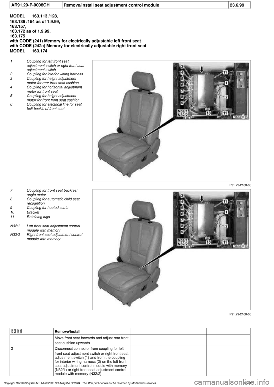
1
Coupling for left front seat
adjustment switch or right front seat
adjustment switch
2
Coupling for interior wiring harness
3
Coupling for height adjustment
motor for rear front seat cushion
4
Coupling for horizontal adjustment
motor for front seat
5
Coupling for height adjustment
motor for front front seat cushion
6
Coupling for electrical line for seat
belt buckle of front seat
P91.29-2108-06
7
Coupling for front seat backrest
angle motor
8
Coupling for automatic child seat
recognition
9
Coupling for heated seats
10
Bracket
11
Retaining lugs
N32/1
Left front seat adjustment control
module with memory
N32/2
Right front seat adjustment control
module with memory
Remove/Install
1
Move front seat forwards and adjust rear front
seat cushion upwards
2
Disconnect connector from coupling for left
front seat adjustment switch or right front seat
adjustment switch (1) and from the coupling
for interior wiring harness (2) on the left front
seat adjustment control module with memory
(N32/1) or right front seat adjustment control
module with memory (N32/2)
Copyright DaimlerChrysler AG 14.06.2006 CD-Ausgabe G/10/04 . This WIS print-out will not be recorde
d by Modification services.
Page 1
Page 3792 of 4133
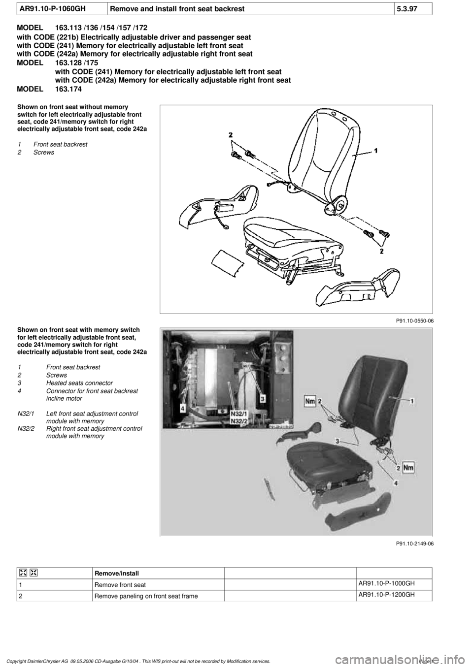
AR91.10-P-1060GH
Remove and install front seat backrest
5.3.97
MODEL
163.113 /136 /154 /157 /172
with CODE (221b) Electrically adjustable driver and passenger seat
with CODE (241) Memory for electrically adjustable left front seat
with CODE (242a) Memory for electrically adjustable right front seat
MODEL
163.128 /175
with CODE (241) Memory for electrically adjustable left front seat
with CODE (242a) Memory for electrically adjustable right front seat
MODEL
163.174
P91.10-0550-06
Shown on front seat without memory
switch for left electrically adjustable front
seat, code 241/memory switch for right
electrically adjustable front seat, code 242a
1
Front seat backrest
2
Screws
P91.10-2149-06
Shown on front seat with memory switch
for left electrically adjustable front seat,
code 241/memory switch for right
electrically adjustable front seat, code 242a
1
Front seat backrest
2
Screws
3
Heated seats connector
4
Connector for front seat backrest
incline motor
N32/1
Left front seat adjustment control
module with memory
N32/2
Right front seat adjustment control
module with memory
Remove/install
1
Remove front seat
AR91.10-P-1000GH
2
Remove paneling on front seat frame
AR91.10-P-1200GH
Copyright DaimlerChrysler AG 09.05.2006 CD-Ausgabe G/10/04 . This WIS print-out will not be recorde
d by Modification services.
Page 1
Page 3793 of 4133
3.1
Disconnect heated seats connector (3) and
connector for front seat backrest incline motor
(4) from left front seat adjustment control
module with memory (N32/1) or right front
seat adjustment control module with memory
(N32/2)
Only for memory switch for left electrically
adjustable front seat, code 241 or memory
switch for right electrically adjustable front
seat, code 242a.
Installation:
Ensure that the electrical
lines are routed properly!
4
Unscrew screws (2) from backrest fittings
*BA91.10-P-1003-01B
Torx bit set
*000589011000
5
Remove front seat backrest (1)
6
Install in the reverse order
Front seats
Number
Designation
Model
Series 163
BA91.10-P-1003-01B
Bolt, front seat backrest to seat frame
Nm
30 (
F
3)
Torx bit set
000 589 01 10 00
Copyright DaimlerChrysler AG 09.05.2006 CD-Ausgabe G/10/04 . This WIS print-out will not be recorde
d by Modification services.
Page 2