Page 965 of 4133
161 Controls in detail
Loading
Removing partition net�
Lift tensioner3 upward to a horizon-
tal position to release tensioning of the
strap.
�
Disengage tie-down hooks1 from
rings2.
�
Remove mounting hooks2
(�page 159) from holder1
(�page 159).
�
Roll up and close the partition net.
�
Store partition net behind rear seat
bench.
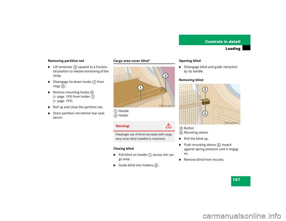
Cargo area cover blind*
1Handle
2Holder
Closing blind�
Pull blind on handle1 across the car-
go area.
�
Guide blind into holders2.Opening blind
�
Disengage blind and guide retraction
by its handle.
Removing blind
3Button
4Mounting sleeve
�
Roll the blind up.
�
Push mounting sleeve4 inward
against spring pressure until it engag-
es.
�
Remove blind from mounts.
Warning!
G
Passenger use of third row seats with cargo
area cover blind installed is restricted.
Page 966 of 4133
162 Controls in detailLoadingInstalling blind�
Place left side of blind in left mount.
�
Position right side of blind over right
mount.
�
Push button3, releasing mounting
sleeve to slide into mount.
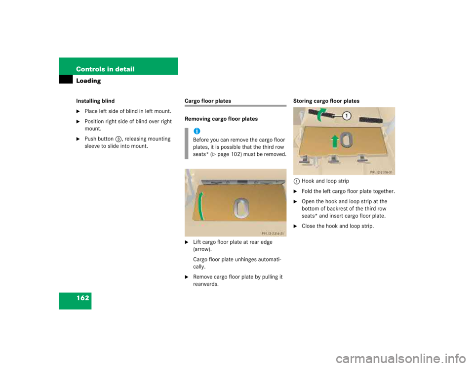
Cargo floor plates
Removing cargo floor plates�
Lift cargo floor plate at rear edge
(arrow).
Cargo floor plate unhinges automati-
cally.
�
Remove cargo floor plate by pulling it
rearwards.Storing cargo floor plates
1Hook and loop strip
�
Fold the left cargo floor plate together.
�
Open the hook and loop strip at the
bottom of backrest of the third row
seats* and insert cargo floor plate.
�
Close the hook and loop strip.
iBefore you can remove the cargo floor
plates, it is possible that the third row
seats* (
�page 102) must be removed.
Page 1043 of 4133
239 Operation
Vehicle care
Upholstery
Using aftermarket seat covers or wearing
clothing that has the tendency to give off
coloring (e.g. when wet, etc.) may cause
the upholstery to become permanently dis-
colored. By lining the seats with a proper
intermediate cover, contact-discoloration
will be prevented.
Leather upholstery*
Wipe leather upholstery with a damp cloth
and dry thoroughly or clean with
Mercedes-Benz approved Leather Care.
E x e r c i s e p a r t i c u l a r c a r e w h e n c l e a n i n g p e r -
forated leather as its underside should not
become wet.MB Tex upholstery
Pour Mercedes-Benz approved Interior
Care onto soft lint-free cloth and apply
with light pressure.
Plastic and rubber parts
Do not use oil or wax on these parts.
Wood trims
Dampen cloth using water and use damp
cloth to clean wood trims in your vehicle.
Do not use solvents like tar remover or
wheel cleaner nor polishes or waxes as
these may be abrasive.
Page 1494 of 4133

AR91.12-P-1010GI
Remove and install bench
21.3.00
MODELS
163.136 /154 /172 as of 1.9.99,
163.113 /128 /157 /174 /175
40 % bench seat
P91.12-2126-06
1
Bolts, front of rear seat fastening
2
Bolts, rear of rear seat fastening
4
Seat frame covering
Remove, Install
1
Remove headrest
See Operating Instructions
2.1
Remove covering (4) on bottom of rear seat
On 40 % rear seat only.
AR91.12-P-1100GH
3.1
Disconnect plug to seat belt buckle cable
Only with side airbag in the rear (left and
right), code 293.
4.1
Remove electric lead attached to seat frame
with adhesive tape
Only with side airbag in the rear (left and
right), code 293.
Installation:
Replace adhesive tape.
5
Unscrew bolts (1) on front of rear seat
fastening
Installation:
Replace bolts and nuts with
locking agent applied.
Torx bit set
*000589011000
*BA91.12-P-1005-03A
6
Release backrest and tip forward
See Operating Instructions
7
Release seat bench and fold down
See Operating Instructions
8
Remove bolts (2) on rear of rear seat fastening
Installation:
Replace bolts and nuts with
locking agent applied.
Torx bit set
*000589011000
*BA91.12-P-1005-03A
9
Remove 40 % bench
10
Install in the reverse order
Rear seats
Number
Designation
Model
163 as of
09/99
BA91.12-P-1005-03A
Nuts for rear seat console on vehicle floor
NM
40
Copyright DaimlerChrysler AG 12.06.2006 CD-Ausgabe G/10/04 . This WIS print-out will not be recorde
d by Modification services.
Page 1
Page 1791 of 4133
Fig. 197: Identifying Woofer Components
Front seats
Remove/install
1Unscrew screws on front
seat console *BA91.10-P-1001-01B
2Angle front seat back
until it rests against the
rear bench seat and fasten
with outer seat belt Cover the floor
covering behind the front
seat to avoid
contamination.
3.1Remove air duct at the
rear of the front seat Only as of VIN
A289565, X754620. 1
screw.
4Detach bass module
speaker connector
(H4/17x1)
5Unscrew screw (2)
6Remove bass module
speaker (H4/17)
7Install in the reverse order
NumberDesignationModel Series 163
BA91.10-P-1001-01BBolt of seating mounting
bracket to vehicle floorNm40
2001 Mercedes-Benz ML320
1998-2005 ACCESSORIES & BODY, CAB Electrical System - Body - 163 Chassis
me
Saturday, October 02, 2010 3:30:09 PMPage 296 © 2006 Mitchell Repair Information Company, LLC.
Page 1814 of 4133
![MERCEDES-BENZ ML320 1997 Complete Repair Manual Front seats
REPLACE FIBER OPTICAL CABLE (D2B) BETWEEN THE RADIO AND E-CALL CONTROL MODULE/CTEL [TEL]
INTERFACE (AFTER TESTING) - AR82.95-P-0015GH
MODEL 163.136 #A as of 051500, 163.136 #X as of 70](/manual-img/4/57305/w960_57305-1813.png "MERCEDES-BENZ ML320 1997 Complete Repair Manual Front seats
REPLACE FIBER OPTICAL CABLE (D2B) BETWEEN THE RADIO AND E-CALL CONTROL MODULE/CTEL [TEL]
INTERFACE (AFTER TESTING) - AR82.95-P-0015GH
MODEL 163.136 #A as of 051500, 163.136 #X as of 70")
Front seats
REPLACE FIBER OPTICAL CABLE (D2B) BETWEEN THE RADIO AND E-CALL CONTROL MODULE/CTEL [TEL]
INTERFACE (AFTER TESTING) - AR82.95-P-0015GH
MODEL 163.136 #A as of 051500, 163.136 #X as of 708319, 163.154 #A as of 051500, 163.154 #X as of
708319, 163.172 #A as of 051500, 163.172 #X as of 708319, 163.113/128/157/174/175 with CODE (852)
CTEL preinstallation assembly at dome with CODE (854) MB portable cellular telephone
MODEL 163.154 /172 /174 #A as of 221506, 163.157/175 with CODE (349) E Call emergency call system
with CODE (494a) USA version
1Remove fuse f8 from fuse
and relay module
2Unscrew screws on front
seat console *BA91.10-P-1001-01B
3Angle front seat back
until it rests against the
rear bench seat and fasten
with outer seat belt Remove wiring
harness for E-call speaker
from E-call bracket.
Cover the floor covering
behind the front seat to
avoid contamination.
4Detach connector (2) and
antenna plug (4) from the
E-call control module
(A35/8)
5Detach conductive
coupling D2B (3) Do not kink or stretch
fiber optic cable. Press
protective caps on
conductive coupling and
device connection.AR82.95-P-0005-01A
6Unscrew screws (5)
7Remove E-call control
module (A35/8)
8Install in the reverse order
NumberDesignationModel Series 163
BA91.10-P-1001-01BBolt of seating mounting
bracket to vehicle floorNm40
2001 Mercedes-Benz ML320
1998-2005 ACCESSORIES & BODY, CAB Electrical System - Body - 163 Chassis
me
Saturday, October 02, 2010 3:30:10 PMPage 319 © 2006 Mitchell Repair Information Company, LLC.
Page 1889 of 4133
Rear seats
Fig. 309: Identifying Torx Bit Set (000 589 01 10 00)
Fig. 310: Identifying Longitudinal Wedge (115 589 03 59 00)
Parts ordering notes
39Install glove
compartment
Remove/install glove
compartment AR68.10-P-1400GI
Torx bit setFig. 309
40Connect ground cable for
battery
Disconnect ground lead
from battery AR54.10-P-0003A
41.1Initialize DVD player As of VIN A289565,
X754620.AZ82.60-P-0004-07GH
NumberDesignationModel 163 as of 09/99
BA91.12-P-1005-03ANuts for rear seat console
on vehicle floorNM40
BA91.12-P-1008-03AScrews for rear seat
console on vehicle floorNM40
Part no.DesignationQuantity
B6 782 6500Monitor, anthracite/orion, with 2
earphones (NTSC)1
2001 Mercedes-Benz ML320
1998-2005 ACCESSORIES & BODY, CAB Electr ical System - Body - 163 Chassis
me
Saturday, October 02, 2010 3:30:12 PMPage 394 © 2006 Mitchell Repair Information Company, LLC.
Page 2541 of 4133
Fig. 31: Identifying Front Axle Shaft Flange And Double-Row Angular Ball Bearing Components
Modification notes
7.8.00Pulling out front axle
shaft flange, changed
Step 2:
The front axle shaft flange is now pulled out using a
stationary press and not with the auxiliary hydraulic
press.
AR33.20-P-
0315-01GI
Remove/Install
1Remove steering knuckle AR33.25-P-
0400GH
2Pull out front axle shaft flange (9)
AR33.20-P-
0315-01GI
Extractor toolFig. 19
Extraction and insertion toolFig. 20
3Detach circlip (9p)
Installation: Ensure that the circlip
seats securely in the wheel carrier.
Pliers for locking ring*WH58.30-Z-
1009-02A
4Pull double-row angular ball bearing
(9n) out of steering knuckle AR33.20-P-
0315-03GH
Extraction and insertion toolFig. 20
AR33.20-P-
0315-04GH
2001 Mercedes-Benz ML320
1998-2005 DRIVELINE/AXLES Front Axle - 163 Chassis
me
Saturday, October 02, 2010 3:38:22 PMPage 22 © 2006 Mitchell Repair Information Company, LLC.
 may cause
the upholstery to become permanent")


Fig. 310: Identifying Longitudinal Wedge (115 589 03 59 00)
Parts ordering notes
39Install glove
compartment
Remove/i")
