Page 3857 of 4133
different engine loads, e.g. power steering turned to full lock, engaging drive mode, switching on AC
compressor
different mixture, e.g. from activated charcoal canister if purging activated (depending on activated
charcoal charge)
Function
The actuator EFP/TPM/LLR (additional designation: throttle valve actuator) regulates the idling speed by
changing the throttle valve position. It is actuated by the ME-SFI control unit.
The ME-SFI control unit actuates the throttle valve motor (M16/1 m1) in line with the input signals received at
the ME-SFI control unit (N3/10).
Heating speed of the catalytic converter
In order to warm up the catalytic converter more rapidly to operating temperature, engine speed is increased in
the idle speed range to 1100 up to 1500 rpm for about 20 seconds after each starting procedure at coolant
temperatures of < 40 °C. When a Drive position is engaged, engine speed is immediately controlled to a lower
value.
Automatic transmission
When a drive position is engaged, a lower engine speed is controlled in order to reduce the creeping tendency o
f
the vehicle. The information "Drive position engaged/not engaged" is transmitted by the ETC control unit
(N15/3) over the CAN databus to the ME-SFI control unit.
Ignition angle
To assist the idle speed control, the ignition angle can be retarded by as much as 36° crank angle or advanced by
as much as 20° crank angle from the calculated specified value.
The control in the idle speed range by altering the ignition angle reacts more rapidly than altering the position o
f
the throttle valve.
The idling speed can be influenced with HHT or the STAR DIAGNOSIS.
AC compressor
In order to avoid engine speed dropping in the idle speed range when the AC compressor is engaged, the AC
push-button control unit (N19) or automatic air conditioning push-button control unit (N22) supplies a signal to
the ME-SFI control unit (as of approx. 6/96 over CAN) and the opening cross-section of the throttle valve is
enlarged.
When the air conditionin
g unit is switched on and the external temperature exceeds 35° C the idling speed on
2001 Mercedes-Benz ML320
1998-2005 ACCESSORIES & BODY CAB Throttle Control, Speed Control Systems - 163 Chassis
me
Saturday, October 02, 2010 3:36:27 PMPage 17 © 2006 Mitchell Repair Information Company, LLC.
Page 3864 of 4133
CRUISE CONTROL (CC) FUNCTION - GF30.30-P-0001FA
ENGINE 112.923 /943, 113.961, 120.983 in MODEL 129
ENGINE 112.942 /970, 113.942 /965 in MODEL 163
ENGINE 111.943 /946 /958 /973 /983, 112.947 in MODEL 170
ENGINE 111.921 /944 /945 as of 1.8.99,
111.952/956/974,
111.975 as of 1.8.99,
112.910/920,113.944
Electronic accelerator/cruise
control/idle speed control actuator
position
Engine 104GF30.22-P-
4010-01D
Engine 111GF30.22-P-
4010-01G
Engine 112, 113GF30.22-P-
4010-01A
Engine 119GF30.22-P-
4010-01E
Engine 120GF30.22-P-
4010-01F
Engine 137GF30.22-P-
4010-01L
Electronic accelerator/cruise
control/idle speed control actuator
task
Determining the opening angle of the throttle valve
in accordance with the operating condition:
Controlling idle speed under different engine
loads (power steering turned to full lock, AC
compressor engaged)
Cruise control mode
Emergency electronic accelerator pedal
Driving, in accordance with accelerator pedal
position.
Electronic accelerator/cruise
control/idle speed control actuator
task
GF30.22-P-
4010-02F
Electronic accelerator/cruise
control/idle speed control actuator
function
GF30.22-P-
4010-03F
2001 Mercedes-Benz ML320
1998-2005 ACCESSORIES & BODY CAB Throttle Control, Speed Control Systems - 163 Chassis
me
Saturday, October 02, 2010 3:36:27 PMPage 24 © 2006 Mitchell Repair Information Company, LLC.
Page 3866 of 4133
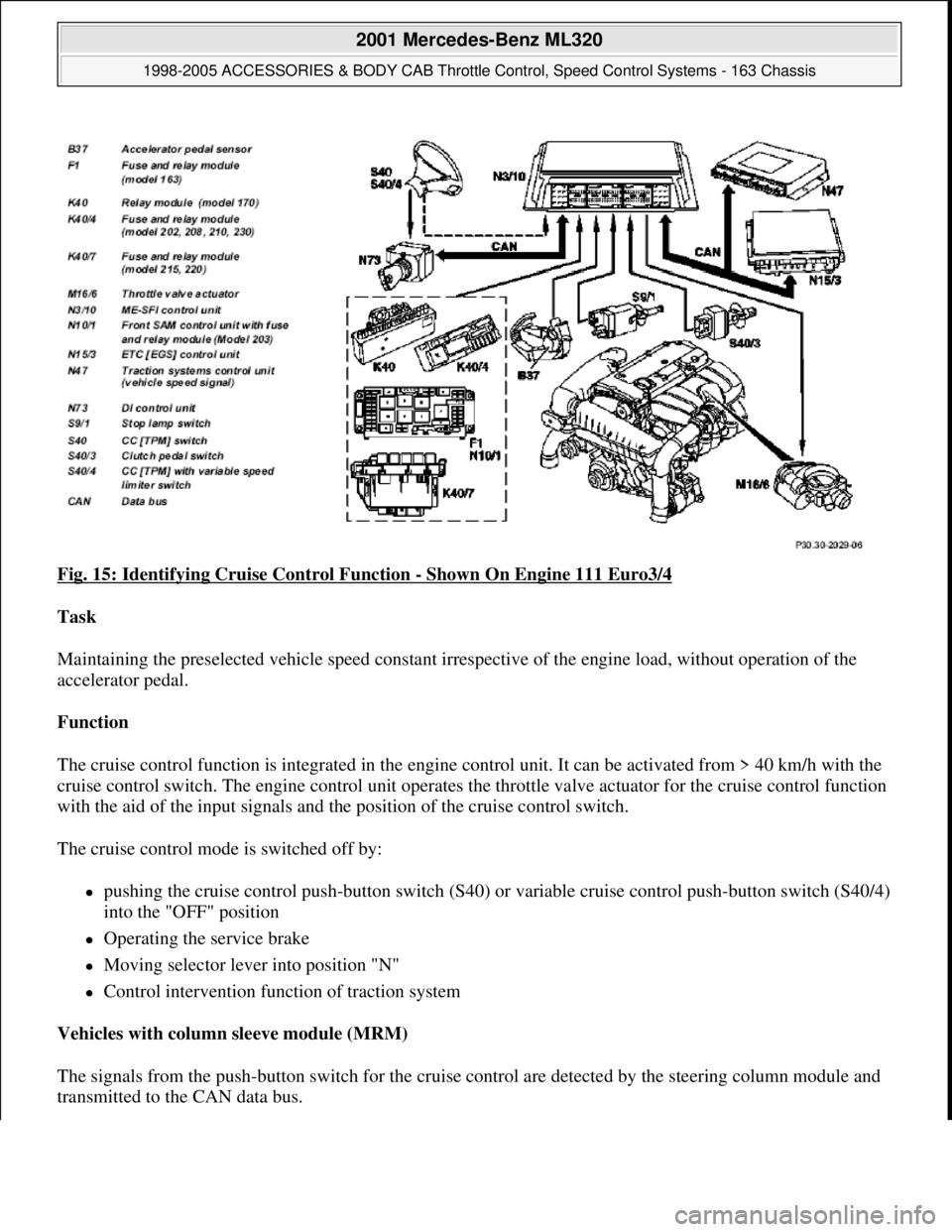
Fig. 15: Identifying Cruise Control Function - Shown On Engine 111 Euro3/4
Task
Maintaining the preselected vehicle speed constant irrespective of the engine load, without operation of the
accelerator pedal.
Function
The cruise control function is integrated in the engine control unit. It can be activated from > 40 km/h with the
cruise control switch. The engine control unit operates the throttle valve actuator for the cruise control function
with the aid of the input signals and the position of the cruise control switch.
The cruise control mode is switched off by:
pushing the cruise control push-button switch (S40) or variable cruise control push-button switch (S40/4)
into the "OFF" position
Operating the service brake
Moving selector lever into position "N"
Control intervention function of traction system
Vehicles with column sleeve module (MRM)
The signals from the push-button switch for the cruise control are detected by the steering column module and
transmitted to the CAN data bus.
2001 Mercedes-Benz ML320
1998-2005 ACCESSORIES & BODY CAB Throttle Control, Speed Control Systems - 163 Chassis
me
Saturday, October 02, 2010 3:36:27 PMPage 26 © 2006 Mitchell Repair Information Company, LLC.
Page 3868 of 4133
111.946 up to 31.5.98,
111.943,
111.973 up to 31.5.97,
111.920,
111.921 up to 31.8.98,
111.941,
111.942 up to 31.8.98,
111.944 up to 31.5.98,
111.945 up to 31.8.98, 111.974,
111.947/970, 112.942 up to 31.5.98,
119, 120 up to 31.5.97,
668.940/941,611.960/961
with CODE (440a) Cruise control
with CODE (443a) Cruise control and electrically adjustable steering column (codes 400 and 441)
with CODE (446) Cruise control, electrically adjustable steering column and airbag (440, 441 and 442)
ENGINE 104, 111, 112, 113, 119, 120, 137, 613.960, 628.960 (except, 112.96, 113.99) with CODE (494a)
USA version
Fig. 16: Identifying Cruise Control Switch
2001 Mercedes-Benz ML320
1998-2005 ACCESSORIES & BODY CAB Throttle Control, Speed Control Systems - 163 Chassis
me
Saturday, October 02, 2010 3:36:27 PMPage 28 © 2006 Mitchell Repair Information Company, LLC.
Page 3869 of 4133
KICKDOWN SWITCH LOCATION/TASK/DESIGN/FUNCTION - GF30.30-P-4000A
ENGINE 112, 113, 119, 120 in MODEL 129
ENGINE 104, 119, 120 in MODEL 140
ENGINE 112, 113 in MODEL 163
ENGINE 166 in MODEL 168
ENGINE 111,112 (except, 112.96) in MODEL 170
ENGINE 111,112, 113 in MODEL 202
ENGINE 111,112 (except, 112.96) in MODEL 203
ENGINE 111,112, 113 in MODEL 208
ENGINE 111,112, 113 in MODEL 210
ENGINE 112,113,137 (except, 113.99) in MODEL 220
ENGINE 113,137 (except 113.99) in MODEL 215
ENGINE 112,113 (except, 113.99) in MODEL 230
ENGINE 112, 113 in MODEL 211
ENGINE 112, 113 in MODEL 209
Cruise control
switch
location
Left top behind the steering wheel.
Cruise control
switch taskSetting of cruise control and Distronic.
With 30 km/h limitation: Switch on and off 30 km/h limitation when below 30
km/h.
Cruise control
switch designPush-button switch with several switching contacts.
Cruise control
switch
functionWhen the cruise control push-button switch is operated, two switching contacts are
always activated simultaneously. The actual input takes place by closing one of the
switching contacts (e.g. storing the speed). The safety contact must close simultaneously
so that the input is accepted.
2001 Mercedes-Benz ML320
1998-2005 ACCESSORIES & BODY CAB Throttle Control, Speed Control Systems - 163 Chassis
me
Saturday, October 02, 2010 3:36:27 PMPage 29 © 2006 Mitchell Repair Information Company, LLC.
Page 3885 of 4133
Fig. 1: Disconnecting Negative Battery Cable
Courtesy of MERCEDES-BENZ OF NORTH AMERICA.
BASIC PROGRAMMING
1. Code radio. See Coding radio .
2. Set time on instrument cluster. Pull out knob at lowe r right of speedometer. To adjust hour, turn to right.
To adjust minute, turn to left.
3. If necessary, set time at stationary heater timer. See owner's manual.
4. Start engine and run at idle. Turn steering wheel fr om one lock position to the other to activate steering
angle sensor. Center steering wheel. Ma lfunction indicator lamp should go out.
5. If equipped, normalize ti lting/sliding roof. Open sunroof and hold down switch. Sunroof moves to end
position and pulls back 1/4 turn and stops. If equipped with lemella slidin
g roof, close roof and keep
2001 Mercedes-Benz ML320
2001-04 STARTING & CHARGING SYSTEMS Starters - 163 Chassis
me
Saturday, October 02, 2010 3:19:47 PMPage 3 © 2006 Mitchell Repair Information Company, LLC.
Page 3895 of 4133
AD54.30-P-6000-06GH
Steering lock switch, testing electrical system
of IC
Model 163
t
A
Scope of test
Measuring instrument/
Test connection
Operation/
Requirement
Specified value
D
Possible cause/
Remedy
1.0
Steering lock switch
(S97/1)
o
A1
bL
14
(A.14)
Ignition:
OFF
Disconnect coupling "A"
(18-pin)
Steering locked
Steering unlocked
<
1
W
> 20 k
W
D
Cables
D
(S97/1)
Copyright DaimlerChrysler AG 05.06.2006 CD-Ausgabe G/10/04 . This WIS print-out will not be recorde
d by Modification services.
Page 1
Page 3896 of 4133
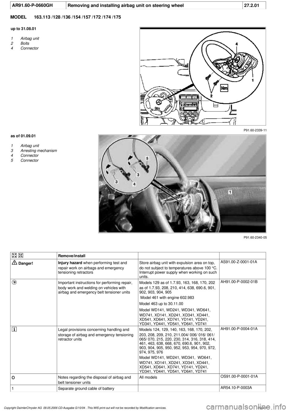
AR91.60-P-0660GH
Removing and installing airbag unit on steering wheel
27.2.01
MODEL
163.113 /128 /136 /154 /157 /172 /174 /175
P91.60-2339-11
up to 31.08.01
1
Airbag unit
2
Bolts
4
Connector
P91.60-2340-05
as of 01.09.01
1
Airbag unit
3
Arresting mechanism
4
Connector
5
Connector
Remove/install
Danger!
Injury hazard
when performing test and
repair work on airbags and emergency
tensioning retractorsStore airbag unit with expulsion area on top,
do not subject to temperatures above 100 °C.
Interrupt power supply when working on such
units.
AS91.00-Z-0001-01A
Important instructions for performing repair,
body work and welding on vehicles with
airbag and emergency belt tensioner units
Models 129 as of 1.7.93, 163, 168, 170, 202
as of 1.7.93, 208, 210, 414, 638, 690.6, 901,
902, 903, 904, 905
Model 461 with engine 602.983
Model 463 up to 30.11.00
Model WD141, WD241, WD341, WD641,
WD741, XD141, XD241, XD341, XD441,
XD541, XD641, XD741, YD141, YD241,
YD341, YD441, YD541, YD641, YD741
AH91.00-P-0002-01B
Legal provisions concerning handling and
storage of airbag and emergency tensioning
retractor units
Models 124, 129, 140, 163, 168, 170, 202,
203, 208, 209, 210, 211.004/ 006/ 016/ 061/
065/ 070, 215, 220, 230, 314, 316, 318, 414,
461, 463, 638, 668, 670, 690.6, 901, 902,
903, 904, 905, 950, 952, 953, 954, 970, 972,
974, 975, 976
Model WD141, WD241, WD341, WD641,
WD741, XD141, XD241, XD341, XD441,
XD541, XD641, XD741, YD141, YD241,
YD341, YD441, YD541, YD641, YD741
AH91.00-P-0004-01A
o
Notes regarding the disposal of airbag and
belt tensioner units
All models
OS91.00-P-0001-01A
1
Separate ground cable of battery
AR54.10-P-0003A
Copyright DaimlerChrysler AG 09.05.2006 CD-Ausgabe G/10/04 . This WIS print-out will not be recorde
d by Modification services.
Page 1