1997 MERCEDES-BENZ ML320 steering
[x] Cancel search: steeringPage 3236 of 4133
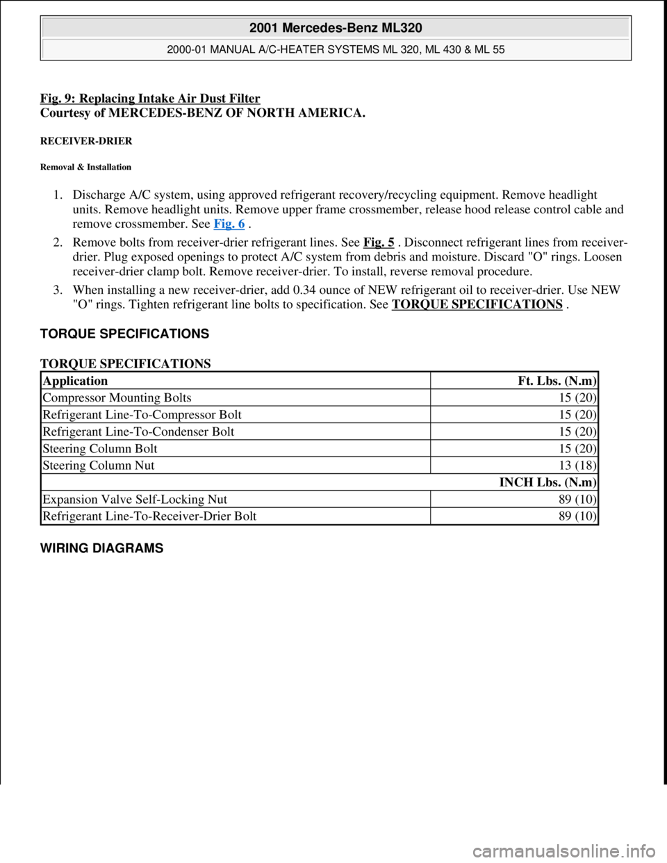
Fig. 9: Replacing Intake Air Dust Filter
Courtesy of MERCEDES-BENZ OF NORTH AMERICA.
RECEIVER-DRIER
Removal & Installation
1. Discharge A/C system, using approved refrigerant recovery/recycling equipment. Remove headlight
units. Remove headlight units. Remove upper frame crossmember, release hood release control cable and
remove crossmember. See Fig. 6
.
2. Remove bolts from receiver-drier refrigerant lines. See Fig. 5
. Disconnect refrigerant lines from receiver-
drier. Plug exposed openings to protect A/C system from debris and moisture. Discard "O" rings. Loosen
receiver-drier clamp bolt. Remove receiver-drier. To install, reverse removal procedure.
3. When installing a new receiver-drier, add 0.34 ounce of NEW refrigerant oil to receiver-drier. Use NEW
"O" rings. Tighten refrigerant line bolts to specification. See TORQUE SPECIFICATIONS
.
TORQUE SPECIFICATIONS
TORQUE SPECIFICATIONS
WIRING DIAGRAMS
ApplicationFt. Lbs. (N.m)
Compressor Mounting Bolts15 (20)
Refrigerant Line-To-Compressor Bolt15 (20)
Refrigerant Line-To-Condenser Bolt15 (20)
Steering Column Bolt15 (20)
Steering Column Nut13 (18)
INCH Lbs. (N.m)
Expansion Valve Self-Locking Nut89 (10)
Refrigerant Line-To-Receiver-Drier Bolt89 (10)
2001 Mercedes-Benz ML320
2000-01 MANUAL A/C-HEATER SYSTEMS ML 320, ML 430 & ML 55
me
Saturday, October 02, 2010 3:25:10 PMPage 25 © 2006 Mitchell Repair Information Company, LLC.
Page 3441 of 4133
poisoning from swallowing
coolant.Wear protective gloves, protective
clothing and eye protection.
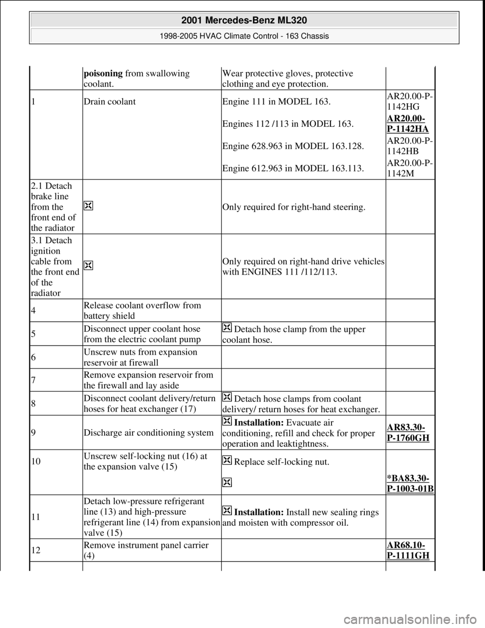
1Drain coolantEngine 111 in MODEL 163.AR20.00-P-
1142HG
Engines 112 /113 in MODEL 163.AR20.00-
P-1142HA
Engine 628.963 in MODEL 163.128.AR20.00-P-
1142HB
Engine 612.963 in MODEL 163.113.AR20.00-P-
1142M
2.1 Detach
brake line
from the
front end of
the radiator
Only required for right-hand steering.
3.1 Detach
ignition
cable from
the front end
of the
radiator
Only required on right-hand drive vehicles
with ENGINES 111 /112/113.
4Release coolant overflow from
battery shield
5Disconnect upper coolant hose
from the electric coolant pump Detach hose clamp from the upper
coolant hose.
6Unscrew nuts from expansion
reservoir at firewall
7Remove expansion reservoir from
the firewall and lay aside
8Disconnect coolant delivery/return
hoses for heat exchanger (17) Detach hose clamps from coolant
delivery/ return hoses for heat exchanger.
9Discharge air conditioning system
Installation: Evacuate air
conditioning, refill and check for proper
operation and leaktightness.AR83.30-
P-1760GH
10Unscrew self-locking nut (16) at
the expansion valve (15) Replace self-locking nut.
*BA83.30-
P-1003-01B
11
Detach low-pressure refrigerant
line (13) and high-pressure
refrigerant line (14) from expansion
valve (15)
Installation: Install new sealing rings
and moisten with compressor oil.
12Remove instrument panel carrier
(4) AR68.10-
P-1111GH
2001 Mercedes-Benz ML320
1998-2005 HVAC Climate Control - 163 Chassis
me
Saturday, October 02, 2010 3:23:18 PMPage 197 © 2006 Mitchell Repair Information Company, LLC.
Page 3466 of 4133
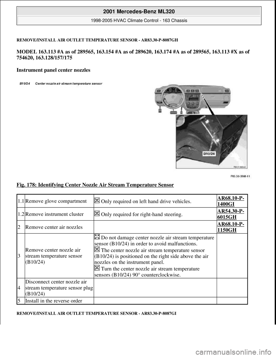
REMOVE/INSTALL AIR OUTLET TEMPERATURE SENSOR - AR83.30-P-8087GH
MODEL 163.113 #A as of 289565, 163.154 #A as of 289620, 163.174 #A as of 289565, 163.113 #X as of
754620, 163.128/157/175
Instrument panel center nozzles
Fig. 178: Identifying Center Nozzle Air Stream Temperature Sensor
REMOVE/INSTALL AIR OUTLET TEMPERATURE SENSOR - AR83.30-P-8087GI
1.1Remove glove compartment Only required on left hand drive vehicles.AR68.10-P-
1400GI
1.2Remove instrument cluster Only required for right-hand steering.AR54.30-P-
6015GH
2Remove center air nozzles AR68.10-P-
1150GH
3
Remove center nozzle air
stream temperature sensor
(B10/24)
Do not damage center nozzle air stream temperature
sensor (B10/24) in order to avoid malfunctions.
The center nozzle air stream temperature sensor
(B10/24) is positioned on the right side above the air
nozzles on the instrument panel.
Turn the center nozzle air stream temperature
sensors (B10/24) 90° counterclockwise.
4
Disconnect center nozzle air
stream temperature sensor plug
(B10/24)
5Install in the reverse order
2001 Mercedes-Benz ML320
1998-2005 HVAC Climate Control - 163 Chassis
me
Saturday, October 02, 2010 3:23:19 PMPage 222 © 2006 Mitchell Repair Information Company, LLC.
Page 3480 of 4133

GF54.30-P-2001A
Indicator / warning displays, function
24.10.96
MODEL
129, 140 as of 1.6.96,
163, 168, 170,
202 as of 1.8.96,
208 up to 31.7.99,
210 as of 1.6.96 up to 30.6.99
The table below lists the various warning alarms and indications
according to type (visual/acoustic) and their actuation (direct/CAN).
Visual warning and indicator signals actuated over direct lines:
D
Left turn signal indicator lamp (A1e1)
D
Right turn signal indicator lamp (A1e2)
D
High beam indicator lamp (A1e3)
D
Fuel reserve warning lamp (A1e4)
D
Brake fluid / parking brake warning lamp (A1e7) (except model
163)
D
Low windshield washer fluid level warning lamp (A1e13) (as of
01.09.01 also valid for model 163)
D
Low engine coolant level warning lamp (A1e11) (except model
168, model 163 as of 3.99)
D
Coolant level and temperature warning lamp (A1e11) (only model
168 as of 9.99 and only coolant level function)
D
Generator charge indicator/warning lamp (A1e5)
D
Seat belt warning lamp (A1e9)
D
Seatbelt/backrest lock warning lamp (A1e9)
D
Exterior lamp failure indicator lamp (A1e14)
-----------------------------------------------------------------------------------------
D
Hydraulic fluid level warning lamp (A1e37)
D
ADS warning lamp, suspension (A1e27)
D
Steering lock warning lamp (A1e40) (only
I
)
D
SRS airbag malfunction indicator lamp (A1e15)
D
AIRBAG OFF indicator lamp (A1e56), only model 163 except
I
Also refer to document: Indicator and warning signals triggered
over CAN data lines
Acoustic warning and indicator signals actuated over direct
lines:
D
Turn signal ticker
D
Seat belt reminder
D
Switched-on lights reminder
D
Key warning
D
Soft top warning, only model 170
Also refer to document: Acoustic warnings, function
Acoustic warning and indicator signals actuated over CAN data
lines:
D
Parking brake warning
D
Vehicle speed warning
D
Vehicle speed limit warning
D
Gear warning, only model 168
Also refer to document: Acoustic warnings, function
Indicator and warning signals triggered over
direct lines
GF54.30-P-3002A
Indicator and warning signals triggered over
CAN data lines
GF54.30-P-3003A
Acoustic warnings, function
GF54.30-P-3010A
Copyright DaimlerChrysler AG 04.06.2006 CD-Ausgabe G/10/04 . This WIS print-out will not be recorde
d by Modification services.
Page 1
Page 3481 of 4133

GF54.30-P-2001A
Indicator / warning displays, function
24.10.96
MODEL
129, 140 as of 1.6.96,
163, 168, 170,
202 as of 1.8.96,
208 up to 31.7.99,
210 as of 1.6.96 up to 30.6.99
The table below lists the various warning alarms and indications
according to type (visual/acoustic) and their actuation (direct/CAN).
Visual warning and indicator signals actuated over direct lines:
D
Left turn signal indicator lamp (A1e1)
D
Right turn signal indicator lamp (A1e2)
D
High beam indicator lamp (A1e3)
D
Fuel reserve warning lamp (A1e4)
D
Brake fluid / parking brake warning lamp (A1e7) (except model
163)
D
Low windshield washer fluid level warning lamp (A1e13) (as of
01.09.01 also valid for model 163)
D
Low engine coolant level warning lamp (A1e11) (except model
168, model 163 as of 3.99)
D
Coolant level and temperature warning lamp (A1e11) (only model
168 as of 9.99 and only coolant level function)
D
Generator charge indicator/warning lamp (A1e5)
D
Seat belt warning lamp (A1e9)
D
Seatbelt/backrest lock warning lamp (A1e9)
D
Exterior lamp failure indicator lamp (A1e14)
-----------------------------------------------------------------------------------------
D
Hydraulic fluid level warning lamp (A1e37)
D
ADS warning lamp, suspension (A1e27)
D
Steering lock warning lamp (A1e40) (only
I
)
D
SRS airbag malfunction indicator lamp (A1e15)
D
AIRBAG OFF indicator lamp (A1e56), only model 163 except
I
Also refer to document: Indicator and warning signals triggered
over CAN data lines
Acoustic warning and indicator signals actuated over direct
lines:
D
Turn signal ticker
D
Seat belt reminder
D
Switched-on lights reminder
D
Key warning
D
Soft top warning, only model 170
Also refer to document: Acoustic warnings, function
Acoustic warning and indicator signals actuated over CAN data
lines:
D
Parking brake warning
D
Vehicle speed warning
D
Vehicle speed limit warning
D
Gear warning, only model 168
Also refer to document: Acoustic warnings, function
Indicator and warning signals triggered over
direct lines
GF54.30-P-3002A
Indicator and warning signals triggered over
CAN data lines
GF54.30-P-3003A
Acoustic warnings, function
GF54.30-P-3010A
Copyright DaimlerChrysler AG 05.06.2006 CD-Ausgabe G/10/04 . This WIS print-out will not be recorde
d by Modification services.
Page 1
Page 3489 of 4133
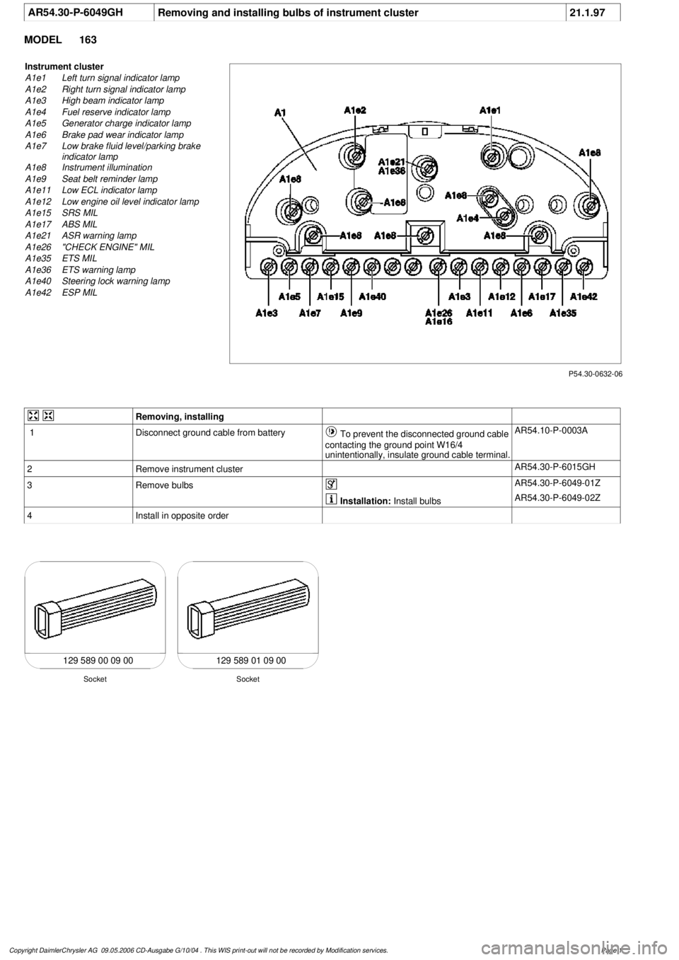
AR54.30-P-6049GH
Removing and installing bulbs of instrument cluster
21.1.97
MODEL
163
P54.30-0632-06
Instrument cluster
A1e1
Left turn signal indicator lamp
A1e2
Right turn signal indicator lamp
A1e3
High beam indicator lamp
A1e4
Fuel reserve indicator lamp
A1e5
Generator charge indicator lamp
A1e6
Brake pad wear indicator lamp
A1e7
Low brake fluid level/parking brake
indicator lamp
A1e8
Instrument illumination
A1e9
Seat belt reminder lamp
A1e11
Low ECL indicator lamp
A1e12
Low engine oil level indicator lamp
A1e15
SRS MIL
A1e17
ABS MIL
A1e21
ASR warning lamp
A1e26
"CHECK ENGINE" MIL
A1e35
ETS MIL
A1e36
ETS warning lamp
A1e40
Steering lock warning lamp
A1e42
ESP MIL
Removing, installing
1
Disconnect ground cable from battery
To prevent the disconnected ground cable
contacting the ground point W16/4
unintentionally, insulate ground cable terminal.
AR54.10-P-0003A
2
Remove instrument cluster
AR54.30-P-6015GH
3
Remove bulbs
AR54.30-P-6049-01Z
Installation:
Install bulbs
AR54.30-P-6049-02Z
4
Install in opposite order
129 589 00 09 00 129 589 01 09 00
Socket
Socket
Copyright DaimlerChrysler AG 09.05.2006 CD-Ausgabe G/10/04 . This WIS print-out will not be recorde
d by Modification services.
Page 1
Page 3493 of 4133
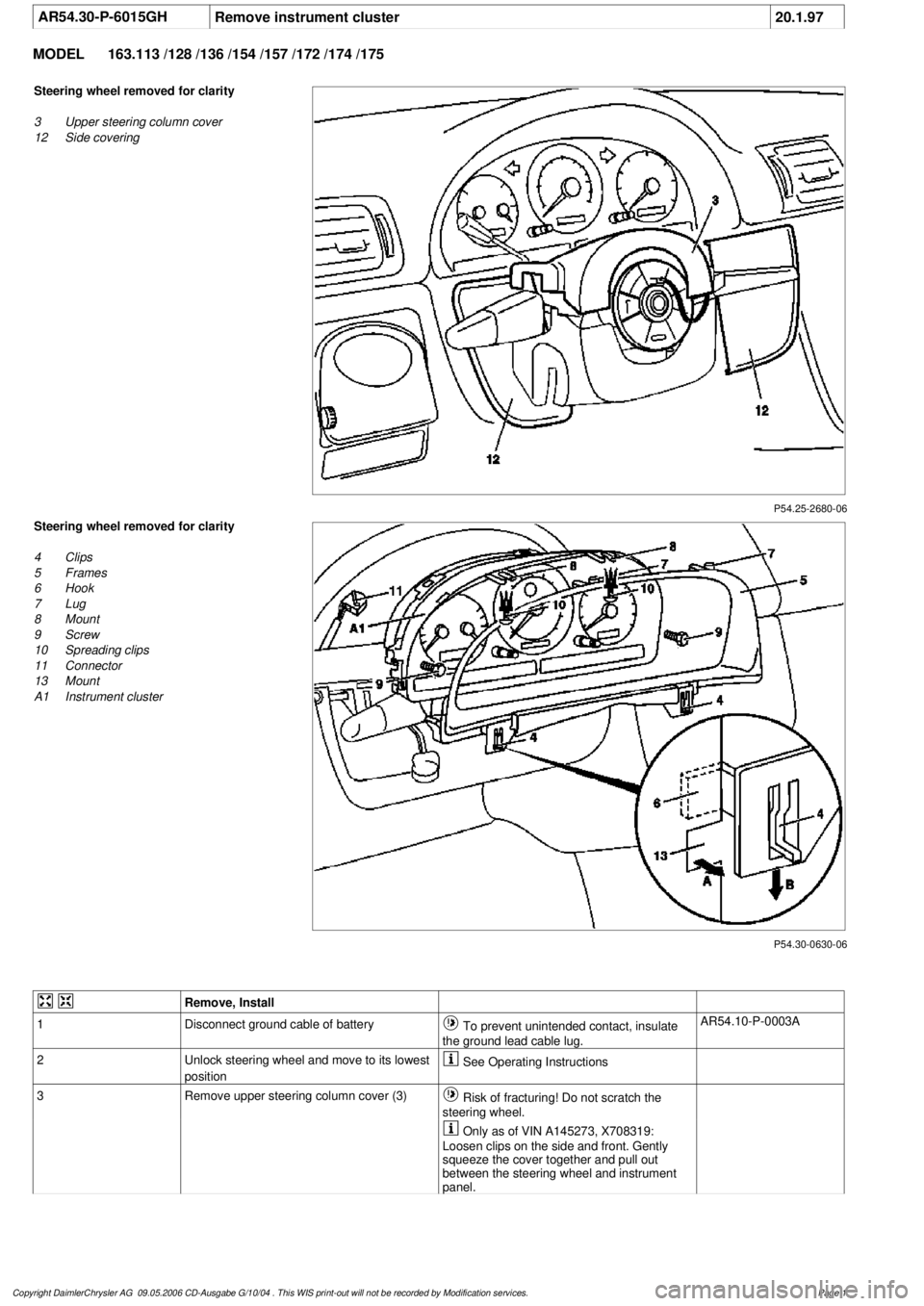
AR54.30-P-6015GH
Remove instrument cluster
20.1.97
MODEL
163.113 /128 /136 /154 /157 /172 /174 /175
P54.25-2680-06
Steering wheel removed for clarity
3
Upper steering column cover
12
Side covering
P54.30-0630-06
Steering wheel removed for clarity
4
Clips
5
Frames
6
Hook
7
Lug
8
Mount
9
Screw
10
Spreading clips
11
Connector
13
Mount
A1
Instrument cluster
Remove, Install
1
Disconnect ground cable of battery
To prevent unintended contact, insulate
the ground lead cable lug.
AR54.10-P-0003A
2
Unlock steering wheel and move to its lowest
position
See Operating Instructions
3
Remove upper steering column cover (3)
Risk of fracturing! Do not scratch the
steering wheel.
Only as of VIN A145273, X708319:
Loosen clips on the side and front. Gently
squeeze the cover together and pull out
between the steering wheel and instrument
panel.
Copyright DaimlerChrysler AG 09.05.2006 CD-Ausgabe G/10/04 . This WIS print-out will not be recorde
d by Modification services.
Page 1
Page 3494 of 4133
4
Remove side covers (12)
Danger of breaking retaining lugs. Do not
damage instrument panel.
Up to VIN A145272, X708318:
3 covers:
Remove side covers first. Detach center
cover from instrument panel and rotate so
that the retaining lugs point upwards. Then
pull out to the right.
As of VIN A145273, X708319:
2 covers: First
remove the right cover, then the left. It is not
necessary to detach the connectors. The
covers can remain attached to the wiring
harness.
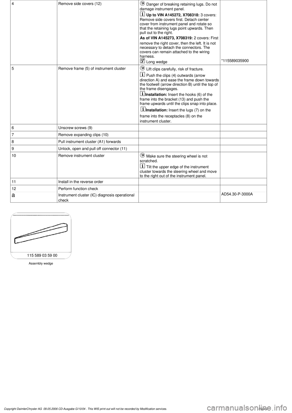
Long wedge
*115589035900
5
Remove frame (5) of instrument cluster
Lift clips carefully, risk of fracture.
Push the clips (4) outwards (arrow
direction A) and ease the frame down towards
the footwell (arrow direction B) until the top of
the frame disengages.
Installation:
Insert the hooks (6) of the
frame into the bracket (13) and push the
frame upwards until the clips snap into place.
Installation:
Insert the lugs (7) on the
frame into the receptacles (8) on the
instrument cluster.
6
Unscrew screws (9)
7
Remove expanding clips (10)
8
Pull instrument cluster (A1) forwards
9
Unlock, open and pull off connector (11)
10
Remove instrument cluster
Make sure the steering wheel is not
scratched.
Tilt the upper edge of the instrument
cluster towards the steering wheel and move
to the right out of the instrument panel.
11
Install in the reverse order
12
Perform function check
a
Instrument cluster (IC) diagnosis operational
check
AD54.30-P-3000A
Assembly wedge
115 589 03 59 00
Copyright DaimlerChrysler AG 09.05.2006 CD-Ausgabe G/10/04 . This WIS print-out will not be recorde
d by Modification services.
Page 2