1997 MERCEDES-BENZ ML320 steering
[x] Cancel search: steeringPage 3150 of 4133
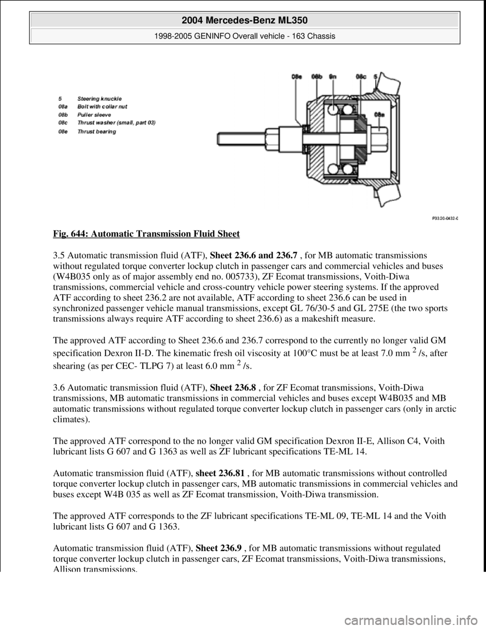
Fig. 644: Automatic Transmission Fluid Sheet
3.5 Automatic transmission fluid (ATF), Sheet 236.6 and 236.7 , for MB automatic transmissions
without regulated torque converter lockup clutch in passenger cars and commercial vehicles and buses
(W4B035 only as of major assembly end no. 005733), ZF Ecomat transmissions, Voith-Diwa
transmissions, commercial vehicle and cross-country vehicle power steering systems. If the approved
ATF according to sheet 236.2 are not available, ATF according to sheet 236.6 can be used in
synchronized passenger vehicle manual transmissions, except GL 76/30-5 and GL 275E (the two sports
transmissions always require ATF according to sheet 236.6) as a makeshift measure.
The approved ATF according to Sheet 236.6 and 236.7 correspond to the currently no longer valid GM
specification Dexron II-D. The kinematic fresh oil viscosity at 100°C must be at least 7.0 mm
2 /s, after
shearing (as per CEC- TLPG 7) at least 6.0 mm
2 /s.
3.6 Automatic transmission fluid (ATF), Sheet 236.8 , for ZF Ecomat transmissions, Voith-Diwa
transmissions, MB automatic transmissions in commercial vehicles and buses except W4B035 and MB
automatic transmissions without regulated torque converter lockup clutch in passenger cars (only in arctic
climates).
The approved ATF correspond to the no longer valid GM specification Dexron II-E, Allison C4, Voith
lubricant lists G 607 and G 1363 as well as ZF lubricant specifications TE-ML 14.
Automatic transmission fluid (ATF), sheet 236.81 , for MB automatic transmissions without controlled
torque converter lockup clutch in passenger cars, MB automatic transmissions in commercial vehicles and
buses except W4B 035 as well as ZF Ecomat transmission, Voith-Diwa transmission.
The approved ATF corresponds to the ZF lubricant specifications TE-ML 09, TE-ML 14 and the Voith
lubricant lists G 607 and G 1363.
Automatic transmission fluid (ATF), Sheet 236.9 , for MB automatic transmissions without regulated
torque converter lockup clutch in passenger cars, ZF Ecomat transmissions, Voith-Diwa transmissions,
Allison transmissions.
2004 Mercedes-Benz ML350
1998-2005 GENINFO Overall vehicle - 163 Chassis
me
Saturday, October 02, 2010 3:47:56 PMPage 505 © 2006 Mitchell Repair Information Company, LLC.
Page 3152 of 4133
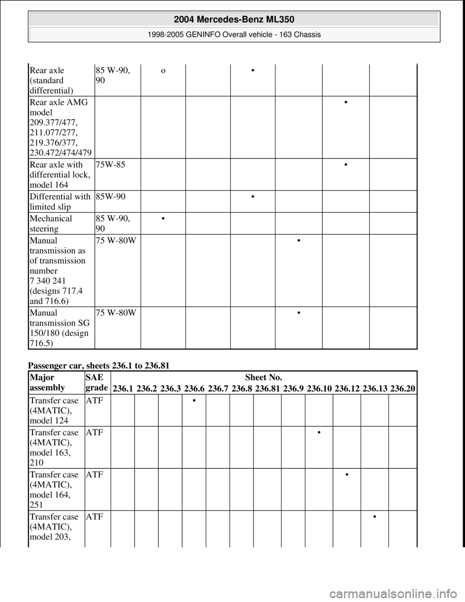
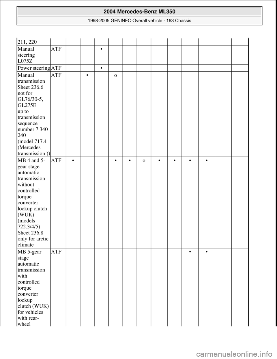
Passenger car, sheets 236.1 to 236.81
Rear axle
(standard
differential)85 W-90,
90o •
Rear axle AMG
model
209.377/477,
211.077/277,
219.376/377,
230.472/474/479 •
Rear axle with
differential lock,
model 16475W-85 •
Differential with
limited slip85W-90 •
Mechanical
steering85 W-90,
90•
Manual
transmission as
of transmission
number
7 340 241
(designs 717.4
and 716.6)75 W-80W •
Manual
transmission SG
150/180 (design
716.5)75 W-80W •
Major
assemblySAE
gradeSheet No.
236.1236.2236.3236.6236.7236.8236.81236.9236.10236.12236.13236.20
Transfer case
(4MATIC),
model 124ATF •
Transfer case
(4MATIC),
model 163,
210ATF •
Transfer case
(4MATIC),
model 164,
251ATF •
Transfer case
(4MATIC),
model 203, ATF •
2004 Mercedes-Benz ML350
1998-2005 GENINFO Overall vehicle - 163 Chassis
me
Saturday, October 02, 2010 3:47:56 PMPage 507 © 2006 Mitchell Repair Information Company, LLC.
Page 3153 of 4133
211, 220
Manual
steering
L075ZATF •
Power steeringATF •
Manual
transmission
Sheet 236.6
not for
GL76/30-5,
GL275E
up to
transmission
sequence
number 7 340
240
(model 717.4
(Mercedes
transmission ))ATF • o
MB 4 and 5-
gear stage
automatic
transmission
without
controlled
torque
converter
lockup clutch
(WUK)
(models
722.3/4/5)
Sheet 236.8
only for arctic
climateATF• ••o••••
MB 5-gear
stage
automatic
transmission
with
controlled
torque
converter
lockup
clutch (WUK)
for vehicles
with rear-
wheel ATF ••
2004 Mercedes-Benz ML350
1998-2005 GENINFO Overall vehicle - 163 Chassis
me
Saturday, October 02, 2010 3:47:56 PMPage 508 © 2006 Mitchell Repair Information Company, LLC.
Page 3155 of 4133
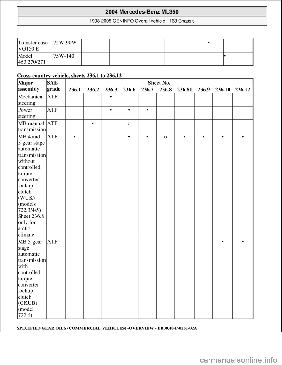
Cross-country vehicle, sheets 236.1 to 236.12
SPECIFIED GEAR OILS (COMMERCIAL VEHICLES) -OVERVIEW - BB00.40-P-0231-02A
Transfer case
VG150 E75W-90W •
Model
463.270/27175W-140 •
Major
assemblySAE
gradeSheet No.
236.1236.2236.3236.6236.7236.8236.81236.9236.10236.12
Mechanical
steeringATF •
Power
steeringATF •••
MB manual
transmissionATF • o
MB 4 and
5-gear stage
automatic
transmission
without
controlled
torque
converter
lockup
clutch
(WUK)
(models
722.3/4/5)
Sheet 236.8
only for
arctic
climateATF• ••o••••
MB 5-gear
stage
automatic
transmission
with
controlled
torque
converter
lockup
clutch
(GKUB)
(model
722.6)ATF ••
2004 Mercedes-Benz ML350
1998-2005 GENINFO Overall vehicle - 163 Chassis
me
Saturday, October 02, 2010 3:47:56 PMPage 510 © 2006 Mitchell Repair Information Company, LLC.
Page 3158 of 4133
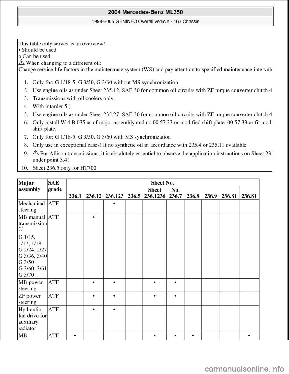
This table only serves as an overview!
• Should be used.
o Can be used.
When changing to a different oil:
Change service life factors in the maintenance system (WS) and pay attention to specified maintenance interval
s
1. Only for: G 1/18-5, G 3/50, G 3/60 without MS synchronization
2. Use engine oils as under Sheet 235.12, SAE 30 for common oil circuits with ZF torque converter clutch 4
0
3. Transmissions with oil coolers only.
4. With intarder 5.)
5. Use engine oils as under Sheet 235.27, SAE 30 for common oil circuits with ZF torque converter clutch 4
0
6. Only install W 4 B 035 as of major assembly end no 00 57 33 or modified shift plate. 00 57 33 or fit modi
shift plate.
7. Only for: G 1/18-5, G 3/50, G 3/60 with MS synchronization
8. Only use in exceptional cases! If no synthetic oil in accordance with 235.4 or 235.11 available.
9. For Allison transmissions, it is absolutely essential to observe the application instructions on Sheet 23
1
under point 3.4!
10. Sheet 236.5 only for HT700
Major
assemblySAE
gradeSheet No.
236.1236.12236.123236.5
Sheet
236.1236No.
236.7
236.8236.9236.81236.81
Mechanical
steeringATF •
MB manual
transmission
7.)
G 1/15,
1/17, 1/18
G 2/24, 2/27
G 3/36, 3/40
G 3/50
G 3/60, 3/61
G 3/70
ATF •
MB power
steeringATF •• ••
ZF power
steeringATF •• ••
Hydraulic
fan drive for
auxiliary
radiatorATF ••
MB ATF• ••• •
2004 Mercedes-Benz ML350
1998-2005 GENINFO Overall vehicle - 163 Chassis
me
Saturday, October 02, 2010 3:47:56 PMPage 513 © 2006 Mitchell Repair Information Company, LLC.
Page 3197 of 4133
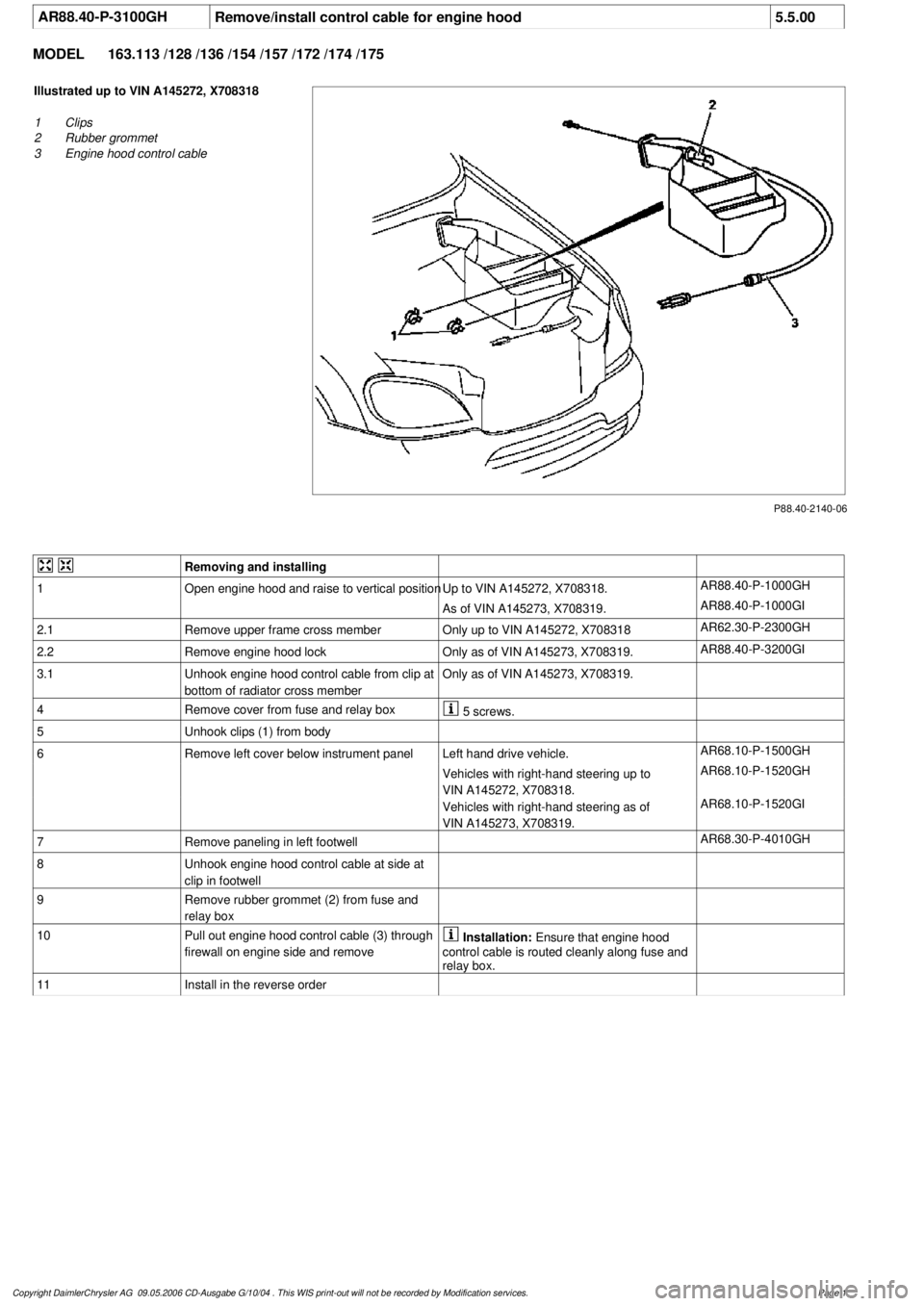
AR88.40-P-3100GH
Remove/install control cable for engine hood
5.5.00
MODEL
163.113 /128 /136 /154 /157 /172 /174 /175
P88.40-2140-06
Illustrated up to VIN A145272, X708318
1
Clips
2
Rubber grommet
3
Engine hood control cable
Removing and installing
1
Open engine hood and raise to vertical position
Up to VIN A145272, X708318.
AR88.40-P-1000GH
As of VIN A145273, X708319.
AR88.40-P-1000GI
2.1
Remove upper frame cross member
Only up to VIN A145272, X708318
AR62.30-P-2300GH
2.2Remove engine hood lock
Only as of VIN A145273, X708319.
AR88.40-P-3200GI
3.1
Unhook engine hood control cable from clip at
bottom of radiator cross member
Only as of VIN A145273, X708319.
4
Remove cover from fuse and relay box
5 screws.
5
Unhook clips (1) from body
6
Remove left cover below instrument panel
Left hand drive vehicle.
AR68.10-P-1500GH
Vehicles with right-hand steering up to
VIN A145272, X708318.
AR68.10-P-1520GH
Vehicles with right-hand steering as of
VIN A145273, X708319.
AR68.10-P-1520GI
7
Remove paneling in left footwell
AR68.30-P-4010GH
8
Unhook engine hood control cable at side at
clip in footwell
9
Remove rubber grommet (2) from fuse and
relay box
10
Pull out engine hood control cable (3) through
firewall on engine side and remove
Installation:
Ensure that engine hood
control cable is routed cleanly along fuse and
relay box.
11
Install in the reverse order
Copyright DaimlerChrysler AG 09.05.2006 CD-Ausgabe G/10/04 . This WIS print-out will not be recorde
d by Modification services.
Page 1
Page 3232 of 4133
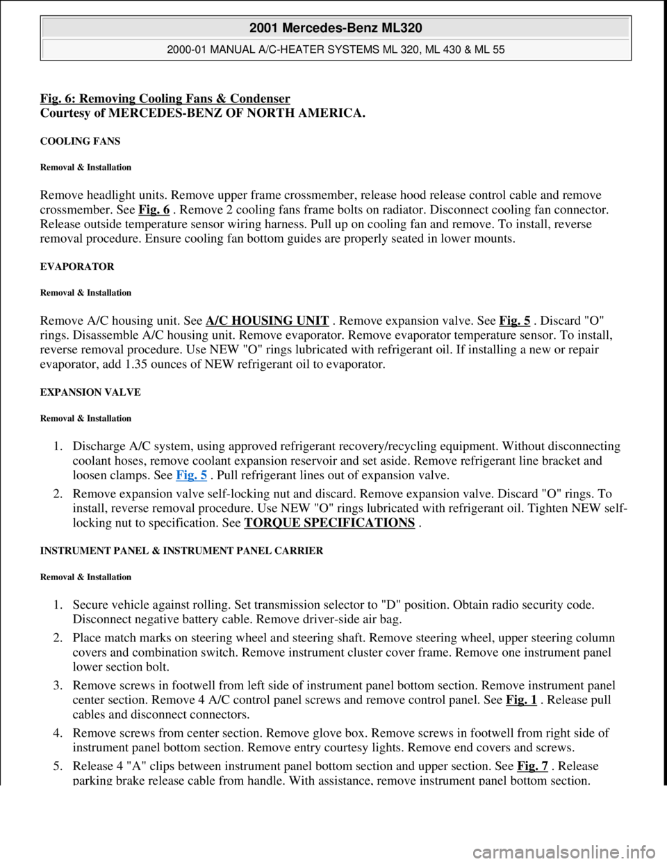
Fig. 6: Removing Cooling Fans & Condenser
Courtesy of MERCEDES-BENZ OF NORTH AMERICA.
COOLING FANS
Removal & Installation
Remove headlight units. Remove upper frame crossmember, release hood release control cable and remove
crossmember. See Fig. 6
. Remove 2 cooling fans frame bolts on radiator. Disconnect cooling fan connector.
Release outside temperature sensor wiring harness. Pull up on cooling fan and remove. To install, reverse
removal procedure. Ensure cooling fan bottom guides are properly seated in lower mounts.
EVAPORATOR
Removal & Installation
Remove A/C housing unit. See A/C HOUSING UNIT . Remove expansion valve. See Fig. 5 . Discard "O"
rings. Disassemble A/C housing unit. Remove evaporator. Remove evaporator temperature sensor. To install,
reverse removal procedure. Use NEW "O" rings lubricated with refrigerant oil. If installing a new or repair
evaporator, add 1.35 ounces of NEW refrigerant oil to evaporator.
EXPANSION VALVE
Removal & Installation
1. Discharge A/C system, using approved refrigerant recovery/recycling equipment. Without disconnecting
coolant hoses, remove coolant expansion reservoir and set aside. Remove refrigerant line bracket and
loosen clamps. See Fig. 5
. Pull refrigerant lines out of expansion valve.
2. Remove expansion valve self-locking nut and discard. Remove expansion valve. Discard "O" rings. To
install, reverse removal procedure. Use NEW "O" rings lubricated with refrigerant oil. Tighten NEW self-
locking nut to specification. See TORQUE SPECIFICATIONS
.
INSTRUMENT PANEL & INSTRUMENT PANEL CARRIER
Removal & Installation
1. Secure vehicle against rolling. Set transmission selector to "D" position. Obtain radio security code.
Disconnect negative battery cable. Remove driver-side air bag.
2. Place match marks on steering wheel and steering shaft. Remove steering wheel, upper steering column
covers and combination switch. Remove instrument cluster cover frame. Remove one instrument panel
lower section bolt.
3. Remove screws in footwell from left side of instrument panel bottom section. Remove instrument panel
center section. Remove 4 A/C control panel screws and remove control panel. See Fig. 1
. Release pull
cables and disconnect connectors.
4. Remove screws from center section. Remove glove box. Remove screws in footwell from right side of
instrument panel bottom section. Remove entry courtesy lights. Remove end covers and screws.
5. Release 4 "A" clips between instrument panel bottom section and upper section. See Fig. 7
. Release
parkin
g brake release cable from handle. With assistance, remove instrument panel bottom section.
2001 Mercedes-Benz ML320
2000-01 MANUAL A/C-HEATER SYSTEMS ML 320, ML 430 & ML 55
me
Saturday, October 02, 2010 3:25:10 PMPage 21 © 2006 Mitchell Repair Information Company, LLC.
Page 3233 of 4133
6. Remove A-pillar panel trim. Remove instrument cluster. Remove defroster vent cover. Remove air vents
and side air nozzles. With assistance, remove upper instrument panel.
7. Remove passenger-side air bag. Remove right side lower instrument panel cover. Remove instrument
panel carrier screws from A/C housing unit. Remove left side lower instrument panel cover.
8. Remove insulating mat between steering column and instrument panel carrier. Remove steering column
bolts and nuts from instrument panel carrier. See Fig. 8
. Remove instrument panel carrier center tunnel
bolts. Disconnect steering column connectors.
9. Remove wiring harness from instrument panel carrier. Remove wiper washer system. Remove instrument
panel carrier nuts from engine compartment side of firewall.
10. Remove A-pillar bolt covers and remove instrument panel carrier A-pillar bolts. With assistance, remove
instrument panel carrier through passenger door. To install, reverse removal procedure.
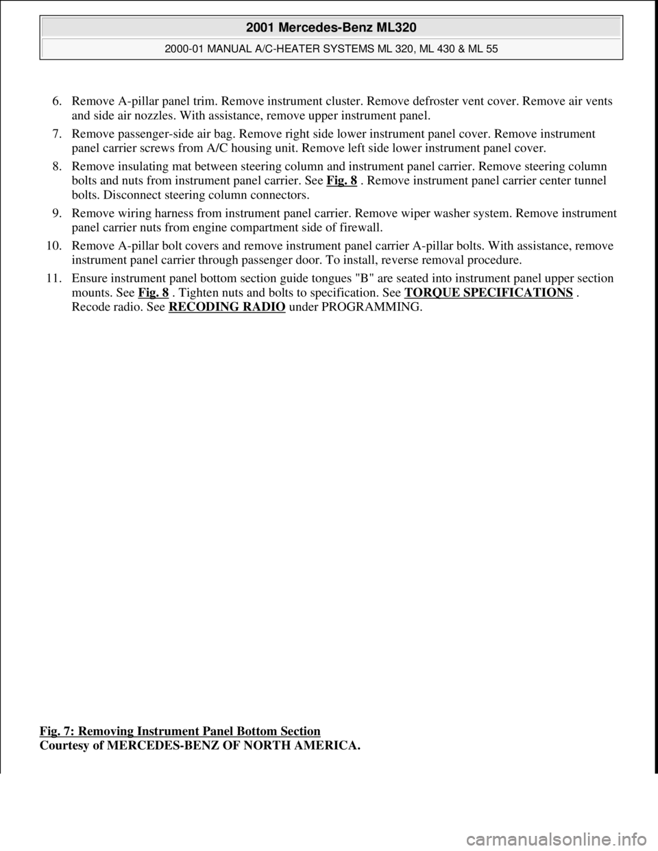
11. Ensure instrument panel bottom section guide tongues "B" are seated into instrument panel upper section
mounts. See Fig. 8
. Tighten nuts and bolts to specification. See TORQUE SPECIFICATIONS .
Recode radio. See RECODING RADIO
under PROGRAMMING.
Fig. 7: Removing Instrument Panel Bottom Section
Courtesy of MERCEDES-BENZ OF NORTH AMERICA.
2001 Mercedes-Benz ML320
2000-01 MANUAL A/C-HEATER SYSTEMS ML 320, ML 430 & ML 55
me
Saturday, October 02, 2010 3:25:10 PMPage 22 © 2006 Mitchell Repair Information Company, LLC.