1997 MERCEDES-BENZ ML320 turn signal
[x] Cancel search: turn signalPage 3527 of 4133

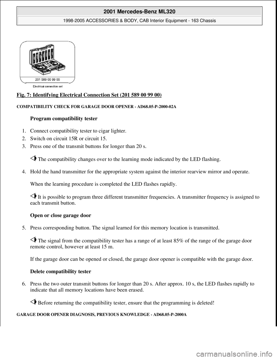
Fig. 7: Identifying Electrical Connection Set (201 589 00 99 00)
COMPATIBILITY CHECK FOR GARAGE DOOR OPENER - AD68.05-P-2000-02A
Program compatibility tester
1. Connect compatibility tester to cigar lighter.
2. Switch on circuit 15R or circuit 15.
3. Press one of the transmit buttons for longer than 20 s.
The compatibility changes over to the learning mode indicated by the LED flashing.
4. Hold the hand transmitter for the appropriate system against the interior rearview mirror and operate.
When the learning procedure is completed the LED flashes rapidly.
It is possible to program three different transmitter frequencies. A transmitter frequency is assigned to
each transmit button.
Open or close garage door
5. Press corresponding button. The signal learned for this memory location is transmitted.
The signal from the compatibility tester has a range of at least 85% of the range of the garage door
remote control, however at least 15 m.
If the garage door can be opened or closed, the garage door opener is compatible with the garage door.
Delete compatibility tester
6. Press the two outer transmit buttons for longer than 20 s. After approx. 10 s, the LED flashes rapidly to
indicate that all memory locations have been erased.
Before returning the compatibility tester, ensure that the programming is deleted!
GARAGE DOOR OPENER DIAGNOSIS, PREVIOUS KNOWLEDGE - AD68.05-P-2000A
2001 Mercedes-Benz ML320
1998-2005 ACCESSORIES & BODY, CAB Interior Equipment - 163 Chassis
me
Saturday, October 02, 2010 3:35:21 PMPage 9 © 2006 Mitchell Repair Information Company, LLC.
Page 3731 of 4133

AR88.70-P-9040GI
Remove/install outside rearview mirror paneling
27.2.01
MODEL
163.113 /154 /174 #A as of 289565,
163.113 /154 /174 #X as of 754620,
163.128 /157 /175
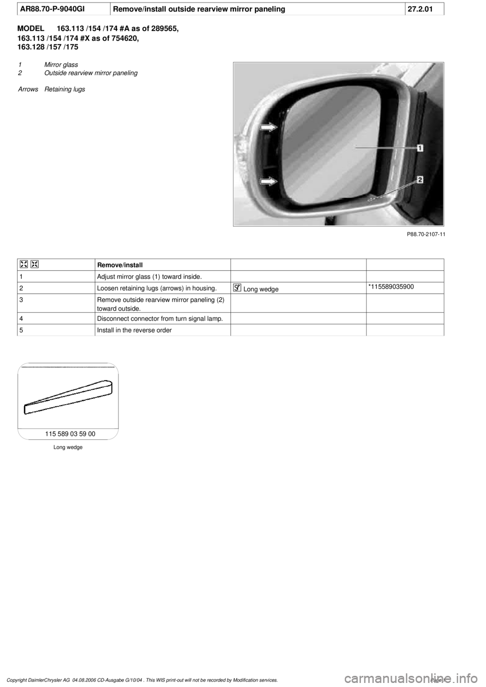
P88.70-2107-11
1
Mirror glass
2
Outside rearview mirror paneling
Arrows Retaining lugs
Remove/install
1
Adjust mirror glass (1) toward inside.
2
Loosen retaining lugs (arrows) in housing.
Long wedge
*115589035900
3
Remove outside rearview mirror paneling (2)
toward outside.
4
Disconnect connector from turn signal lamp.
5
Install in the reverse order
Long wedge
115 589 03 59 00
Copyright DaimlerChrysler AG 04.08.2006 CD-Ausgabe G/10/04 . This WIS print-out will not be recorde
d by Modification services.
Page 1
Page 3734 of 4133

GF54.30-P-4104A
Outside temperature display, location/function
8.7.99
MODEL
129
MODEL
140 as of 1.6.96
MODEL
170
MODEL
163, 202 with CODE (240a) Outside temperature display
MODEL
202 as of 1.8.96
MODEL
168
MODEL
208 up to 31.7.99,
210 as of 1.6.96 up to 30.6.99
To display the temperature, the
outside temperature indicator
A1p4
requires:
D
the outside temperature
D
the speed signal
D
the engine running time
and
D
the coolant temperature (model 129, and model 140 as of
1.6.96, model 170, model 202 as of 08/96 and model 163,
model 168, model 210)
The outside temperature is determined by the outside temperature
indicator temperature sensor B14. The temperature sensor is
installed at the front left of the vehicle under the bumper and
connected to the instrument cluster A1 via the 21 or 25-pin
connector, coding part A terminal 1 and 2.
The speed signal, engine running time and engine temperature are
determined internally by the instrument cluster A1.
Since the outside temperature display depends on the speed, engine
running time and coolant temperature, high temperatures (influenced
by the heat generated by the engine, for example) are not displayed
when the vehicle is stationary or moving slowly.
Function, model 202 until 08/95
When the ignition is switched on and off and at speeds below approx.
20 km/h, the last temperature measured is stored and displayed.
If the measured outside temperature drops below the stored value,
the current measured temperature is displayed.
If the outside temperature rises above the stored value, the current
measured outside temperature is displayed only after the following
delays:
D
When the engine is not running, the current outside
temperature is only displayed after 6 times the engine running
time. For example, if the preceding running time was 5 minutes,
the current temperature is not displayed until after 30 minutes.
The maximum delay, however, is 1 hour.
Up to 09.94
D
At vehicle speeds between 20-60 km/h, outside temperatures
are displayed after a delay of approx. 5 min.
D
At vehicle speeds over 60 km/h, outside temperatures are
displayed after a delay of approx. 2 minutes.
As of 09.94
D
At vehicle speeds between 20-45 km/h, outside temperatures
are displayed after a delay of approx. 3 min.
D
At vehicle speeds over 45 km/h, outside temperatures are
displayed after a delay of approx. 1.5 min.
Function
Model 129, model 140 as of 1.6.96, model 170, model 202 as of
08/96, model 163, model 168, model 208 and model 210
D
When the ignition is turned on or off
and with an engine temperature < 60°C
the current temperature is always stored and displayed.
D
When the ignition is turned off
and with an engine temperature < 60°C
the temperature last measured is stored and displayed.
D
When the ignition is turned on
and when an engine temperature < 60(C
The stored temperature is displayed.
If the measured outside temperature drops below the stored value,
the current measured temperature is displayed.
If the outside temperature rises above the stored value, the current
measured outside temperature is displayed only after the following
delays:
D
When the engine is not running, the current outside
temperature is only displayed after 6 times the engine running
time. For example, if the preceding running time was 5 minutes,
the current temperature is not displayed until after 30 minutes.
The maximum delay, however, is 1 hour.
D
At vehicle speeds between 20-45 km/h, outside temperatures
are displayed after a delay of approx. 3 minutes.
D
At vehicle speeds above 45 km/h, outside temperatures are
displayed after a delay of approx. 1.5 minutes.
Copyright DaimlerChrysler AG 05.06.2006 CD-Ausgabe G/10/04 . This WIS print-out will not be recorde
d by Modification services.
Page 1
Page 3857 of 4133

different engine loads, e.g. power steering turned to full lock, engaging drive mode, switching on AC
compressor
different mixture, e.g. from activated charcoal canister if purging activated (depending on activated
charcoal charge)
Function
The actuator EFP/TPM/LLR (additional designation: throttle valve actuator) regulates the idling speed by
changing the throttle valve position. It is actuated by the ME-SFI control unit.
The ME-SFI control unit actuates the throttle valve motor (M16/1 m1) in line with the input signals received at
the ME-SFI control unit (N3/10).
Heating speed of the catalytic converter
In order to warm up the catalytic converter more rapidly to operating temperature, engine speed is increased in
the idle speed range to 1100 up to 1500 rpm for about 20 seconds after each starting procedure at coolant
temperatures of < 40 °C. When a Drive position is engaged, engine speed is immediately controlled to a lower
value.
Automatic transmission
When a drive position is engaged, a lower engine speed is controlled in order to reduce the creeping tendency o
f
the vehicle. The information "Drive position engaged/not engaged" is transmitted by the ETC control unit
(N15/3) over the CAN databus to the ME-SFI control unit.
Ignition angle
To assist the idle speed control, the ignition angle can be retarded by as much as 36° crank angle or advanced by
as much as 20° crank angle from the calculated specified value.
The control in the idle speed range by altering the ignition angle reacts more rapidly than altering the position o
f
the throttle valve.
The idling speed can be influenced with HHT or the STAR DIAGNOSIS.
AC compressor
In order to avoid engine speed dropping in the idle speed range when the AC compressor is engaged, the AC
push-button control unit (N19) or automatic air conditioning push-button control unit (N22) supplies a signal to
the ME-SFI control unit (as of approx. 6/96 over CAN) and the opening cross-section of the throttle valve is
enlarged.
When the air conditionin
g unit is switched on and the external temperature exceeds 35° C the idling speed on
2001 Mercedes-Benz ML320
1998-2005 ACCESSORIES & BODY CAB Throttle Control, Speed Control Systems - 163 Chassis
me
Saturday, October 02, 2010 3:36:27 PMPage 17 © 2006 Mitchell Repair Information Company, LLC.
Page 3900 of 4133

5
Remove key and engage steering lock
6
Unscrew bolt (32c)
Hold the steering wheel (32).
Installation:
Replace bolt (32c).
*BA46.10-P-1001-02A
7
Pull off steering wheel (32)
Pass cables carefully through the openings.
Installation:
Align recesses of the splines
in the steering wheel with the markings on the
steering shaft (arrows).
8
Check fanfare horns and airbag clock spring
contact (A45) for damage
The clock spring contact must not be
turned while the steering wheel is removed
otherwise it will be damaged.
Visual inspection, replace clock spring
contact if necessary:
#
Removing and installing clock spring contact
AR46.10-P-0200GH
9
Install in the reverse order
10
Carry out road test
Tests during the road test:
Turn signal canceling:
When the steering wheel is offset by
more than 1 tooth, satisfactory resetting of the
turn signal is no longer guaranteed.
Airbag indicator lamp:
The SRS indicator lamp must not light up
on full steering lock in both directions.
Steering wheel position:
If the steering wheel is crooked, adjust it
by max. 1 tooth. If the difference is greater:
#
Check toe on front axle and adjust if
necessary, see:
#
Performing chassis alignment check
AR40.20-P-0200A
Steering wheel
Number
Designation
Model 163
BA46.10-P-1001-02A
Bolt, steering wheel to steering shaft
Nm
80
Copyright DaimlerChrysler AG 09.05.2006 CD-Ausgabe G/10/04 . This WIS print-out will not be recorde
d by Modification services.
Page 2
Page 3960 of 4133

AD54.30-P-5000-03A
Directly controlled display instruments
troubleshooting chart IC
Directly controlled display instruments or indicator
lamp/warning message:
D
Outside temperature indicator
D
Fuel gauge
D
Oil pressure gauge (models 129 and 140 only)
D
Left turn signal indicator lamp
D
Right turn signal indicator lamp
D
High beam indicator lamp
D
Fuel reserve indicator lamp
D
Airbag SRS indicator lamp/MIL
D
AIRBAG OFF indicator lamp (only model 163 except
I )
D
Low brake fluid level/parking brake indicator lamp (only brake
fluid direct)
(both functions via CAN on model 163)
D
Low windshield washer fluid level indicator lamp (except
models 163 and 168)
D
Low ECL indicator lamp (except models 163 and 168)
D
Generator charge indicator lamp
D
Seat belt reminder lamp
D
Seat belt/backrest lock reminder lamp
D
Exterior lamp failure indicator lamp
D
Hydraulic fluid level indicator lamp (models 202 and 210 only)
D
ADS MIL, suspension
D
Turn signal clicking
D
Seat belt reminder lamp
D
Light reminder lamp
D
Key reminder lamp
D
Soft top reminder lamp (model 170 only)
D
Steering lock warning lamp (
I )
Copyright DaimlerChrysler AG 05.06.2006 CD-Ausgabe G/10/04 . This WIS print-out will not be recorde
d by Modification services.
Page 1