1997 MERCEDES-BENZ ML320 turn signal
[x] Cancel search: turn signalPage 3213 of 4133
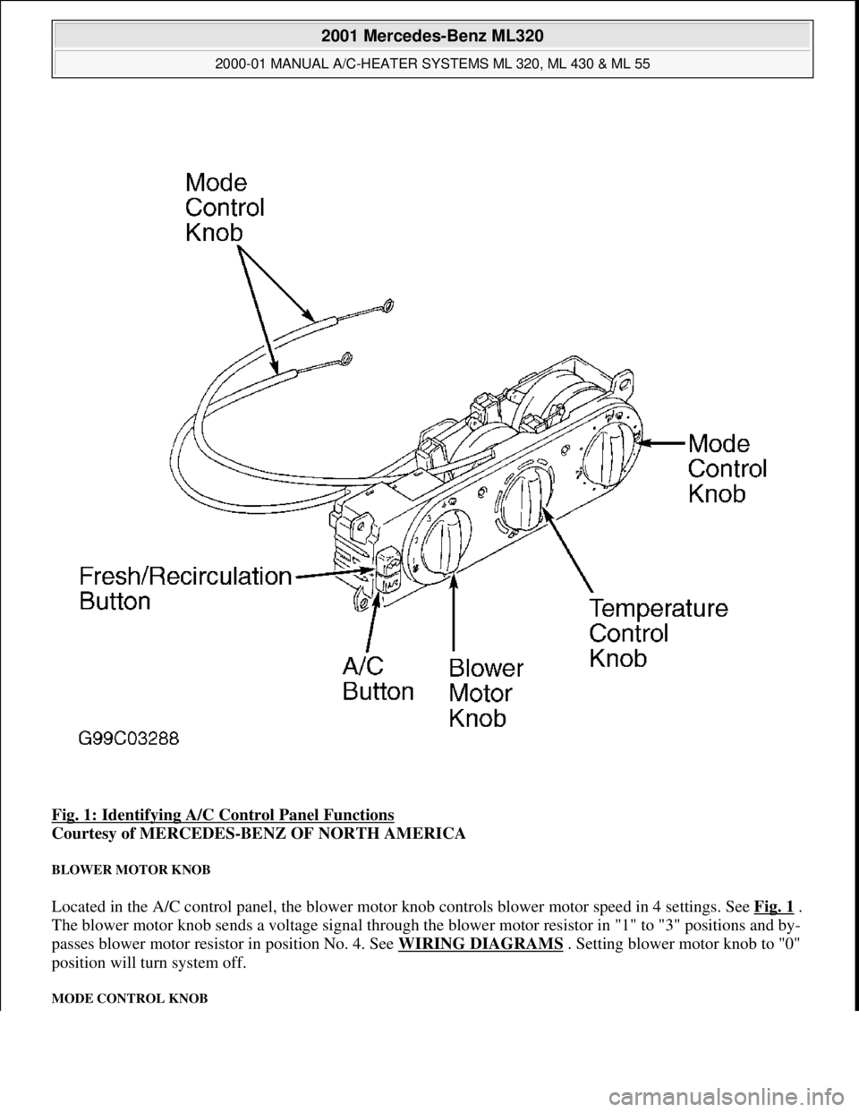
Fig. 1: Identifying A/C Control Panel Functions
Courtesy of MERCEDES-BENZ OF NORTH AMERICA
BLOWER MOTOR KNOB
Located in the A/C control panel, the blower motor knob controls blower motor speed in 4 settings. See Fig. 1 .
The blower motor knob sends a voltage signal through the blower motor resistor in "1" to "3" positions and by-
passes blower motor resistor in position No. 4. See WIRING DIAGRAMS . Setting blower motor knob to "0"
position will turn system off.
MODE CONTROL KNOB
2001 Mercedes-Benz ML320
2000-01 MANUAL A/C-HEATER SYSTEMS ML 320, ML 430 & ML 55
me
Saturday, October 02, 2010 3:25:10 PMPage 2 © 2006 Mitchell Repair Information Company, LLC.
Page 3220 of 4133
FUNCTIONAL TEST PREPARATION
1. Check condition of fuses F16, F41, F43 and F44. See WIRING DIAGRAMS . Repair and/or replace
fuses and necessary.
2. Turn ignition on. Locate in-vehicle temperature sensor aspirator blower vent grille above anti-theft
indicator light. Place a half-inch square of tissue paper over aspirator blower vent grille. If paper stays on
vent grille, go to next step. If paper does not stay on vent grille, correct insufficient aspirator blower
ventilation.
3. Put shift lever in "P" and engage parking brake. Run engine at idle until it reaches normal operating
temperature, about 176°F (80°C). Ensure ambient (outside) temperature is greater than 58°F (15°C).
4. Manually open center and side air outlets. Ensure recirculation button is not depressed. Set blower speed
knob to position No. 1.
FUNCTION TEST
Defrost Mode
To check operation in defrost mode, set temperature selector knob to White range (vertical). Set mode control
knob to 12-o'clock position (vertical). Ensure A/C button indicator is illuminated. Air will vent from defrost and
center outlets and A/C compressor will engage. If operation is not as specified, perform the following in order:
Check voltage supply circuit Z50/2 between No. 16 fuse (15-amp) and connected components. See
VOLTAGE SUPPLY CIRCUIT Z50/2
under ELECTRICAL TESTS.
Check ground circuit. See GROUND CIRCUIT Z50/4 under ELECTRICAL TESTS.
Check in-vehicle temperature sensor signal voltage. See IN-VEHICLE TEMPERATURE SENSOR
under ELECTRICAL TESTS.
Check in-vehicle temperature sensor signal resistance. See IN-VEHICLE TEMPERATURE SENSOR
under ELECTRICAL TESTS.
Check icing protection temperature sensor signal voltage. See ICING PROTECTION
TEMPERATURE SENSOR under ELECTRICAL TESTS.
Check icing protection temperature sensor resistance. See ICING PROTECTION TEMPERATURE
SENSOR under ELECTRICAL TESTS.
Check activation voltage during temperature reduction. See ACTIVATION VOLTAGE
TEMPERATURE under ELECTRICAL TESTS.
Check activation voltage during temperature increase. See ACTIVATION VOLTAGE
TEMPERATURE under ELECTRICAL TESTS.
Check blend air flap actuator motor operation voltage. See BLEND AIR FLAP ACTUATOR MOTOR
under ELECTRICAL TESTS.
Check blend air flap actuator motor resistance. See BLEND AIR FLAP ACTUATOR MOTOR under
ELECTRICAL TESTS.
Check A/C button activation. See A/C BUTTON under ELECTRICAL TESTS.
Check A/C pressure switch. See A/C REFRIGERANT PRESSURE SWITCH under ELECTRICAL NOTE: Function test steps must be performed in order given.
2001 Mercedes-Benz ML320
2000-01 MANUAL A/C-HEATER SYSTEMS ML 320, ML 430 & ML 55
me
Saturday, October 02, 2010 3:25:10 PMPage 9 © 2006 Mitchell Repair Information Company, LLC.
Page 3301 of 4133
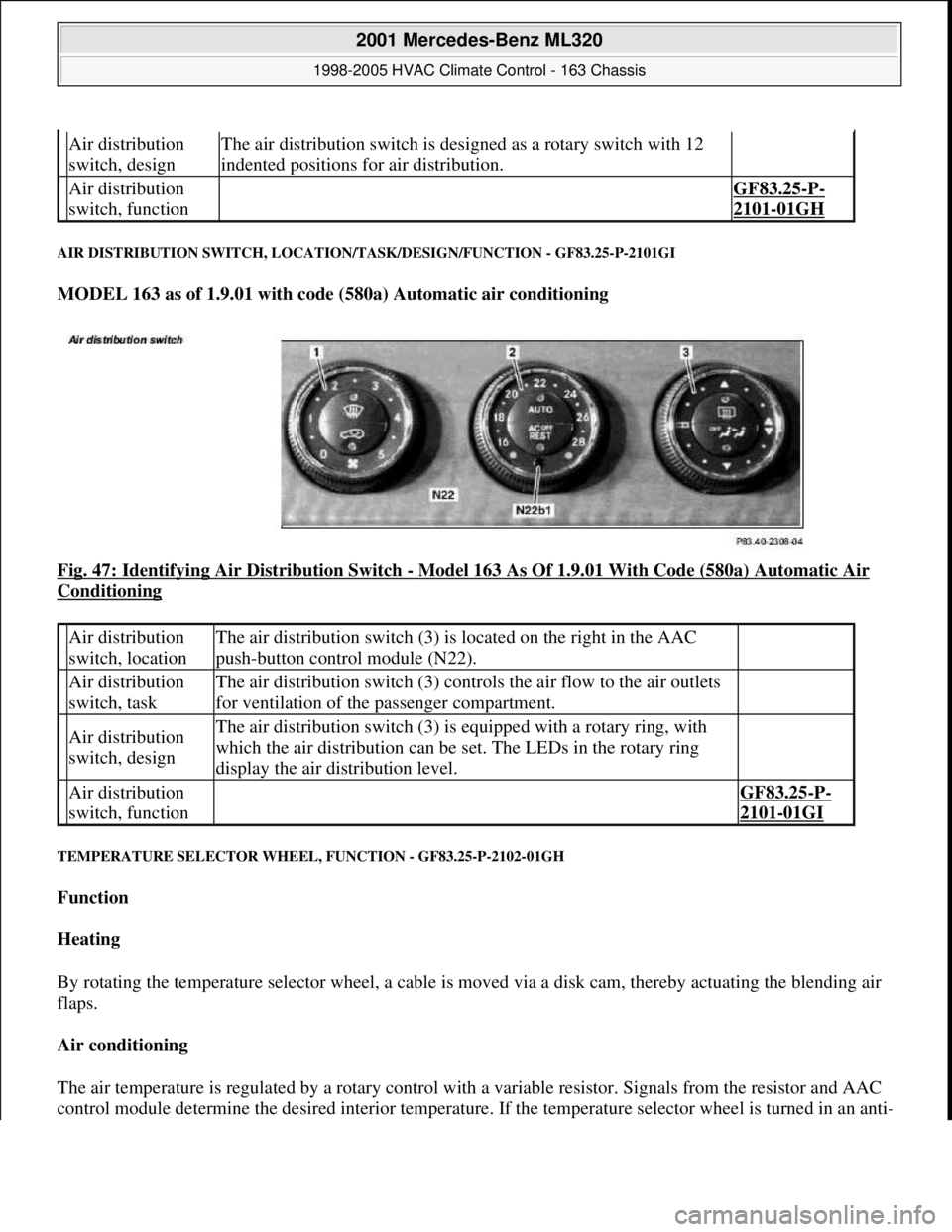
AIR DISTRIBUTION SWITCH, LOCATION/TASK/DESIGN/FUNCTION - GF83.25-P-2101GI
MODEL 163 as of 1.9.01 with code (580a) Automatic air conditioning
Fig. 47: Identifying Air Distribution Switch
- Model 163 As Of 1.9.01 With Code (580a) Automatic Air
Conditioning
TEMPERATURE SELECTOR WHEEL, FUNCTION - GF83.25-P-2102-01GH
Function
Heating
By rotating the temperature selector wheel, a cable is moved via a disk cam, thereby actuating the blending air
flaps.
Air conditioning
The air temperature is regulated by a rotary control with a variable resistor. Signals from the resistor and AAC
control module determine the desired interior temperature. If the temperature selector wheel is turned in an anti-
Air distribution
switch, designThe air distribution switch is designed as a rotary switch with 12
indented positions for air distribution.
Air distribution
switch, function GF83.25-P-
2101-01GH
Air distribution
switch, locationThe air distribution switch (3) is located on the right in the AAC
push-button control module (N22).
Air distribution
switch, taskThe air distribution switch (3) controls the air flow to the air outlets
for ventilation of the passenger compartment.
Air distribution
switch, designThe air distribution switch (3) is equipped with a rotary ring, with
which the air distribution can be set. The LEDs in the rotary ring
display the air distribution level.
Air distribution
switch, function GF83.25-P-
2101-01GI
2001 Mercedes-Benz ML320
1998-2005 HVAC Climate Control - 163 Chassis
me
Saturday, October 02, 2010 3:23:15 PMPage 57 © 2006 Mitchell Repair Information Company, LLC.
Page 3325 of 4133
The residual engine heat utilization system allows the vehicle to be heated even when the ignition is
switched OFF. To do so the system utilizes the residual heat from the engine and guides it via the
blower into the passenger compartment. The heating water circulation pump ensures that the
coolant is properly circulated.
Automatic air conditioning push-button control module
The automatic air conditioning can be operated by the driver using various tip switches. Apart from this
the push-
button control module reads in different sensor signals, processes them and controls components
in the automatic air conditioning.
Rear ventilation control panel
The operator can intervene in the automatic regulation of the rear ventilation through the automatic air
conditioning by using the rear ventilation control panel and adjust it accordingly to suit needs at any
given time. With the aid of the air distribution switch and blower switch the operator can accommodate
his/her own wishes. The correspondingly altered function is then no longer regulated by the automatic air
conditioning.
By pressing the automatic control button the manually initiated settings can be reset and thus regulated
again by the automatic air conditioning.
Regulation of the air quantity and air distribution ensues thus solely by way of the automatic air
conditioning push-button control module.
Heater circuit
Coolant is heated by the engine. Subsequently, the heated coolant is then routed through the heat exchanger,
where the heat is dissipated to the air in the passenger compartment. The heater return line, in which the heating
water circulation pump is located, takes the coolant back to the coolant pump.
The heating water circulation pump ensures that the coolant is properly circulated.
The coolant flows through the heat exchanger permanently.
Depending upon the desired in-car temperature, regulation is conducted over the blending air flaps, which are
operated by the blending air flap actuator motor.
Heater operation with heater booster in vehicles with OM 612.963
In vehicles equipped with direct-injection diesel engines, an electrical heater booster is additionally installed in
the evaporator housing downstream of the heat exchanger, in order to compensate the heater output deficit
which occurs in the case of certain operating conditions.
The 3 heating elements in the heater booster are supplied with current, as a result of which they are heated and
start to glow. As a result of the structural conditions, it is ensured that the drawn in fresh air flows directly past
the electric heater booster, and is therefore heated.
2001 Mercedes-Benz ML320
1998-2005 HVAC Climate Control - 163 Chassis
me
Saturday, October 02, 2010 3:23:16 PMPage 81 © 2006 Mitchell Repair Information Company, LLC.
Page 3480 of 4133

GF54.30-P-2001A
Indicator / warning displays, function
24.10.96
MODEL
129, 140 as of 1.6.96,
163, 168, 170,
202 as of 1.8.96,
208 up to 31.7.99,
210 as of 1.6.96 up to 30.6.99
The table below lists the various warning alarms and indications
according to type (visual/acoustic) and their actuation (direct/CAN).
Visual warning and indicator signals actuated over direct lines:
D
Left turn signal indicator lamp (A1e1)
D
Right turn signal indicator lamp (A1e2)
D
High beam indicator lamp (A1e3)
D
Fuel reserve warning lamp (A1e4)
D
Brake fluid / parking brake warning lamp (A1e7) (except model
163)
D
Low windshield washer fluid level warning lamp (A1e13) (as of
01.09.01 also valid for model 163)
D
Low engine coolant level warning lamp (A1e11) (except model
168, model 163 as of 3.99)
D
Coolant level and temperature warning lamp (A1e11) (only model
168 as of 9.99 and only coolant level function)
D
Generator charge indicator/warning lamp (A1e5)
D
Seat belt warning lamp (A1e9)
D
Seatbelt/backrest lock warning lamp (A1e9)
D
Exterior lamp failure indicator lamp (A1e14)
-----------------------------------------------------------------------------------------
D
Hydraulic fluid level warning lamp (A1e37)
D
ADS warning lamp, suspension (A1e27)
D
Steering lock warning lamp (A1e40) (only
I
)
D
SRS airbag malfunction indicator lamp (A1e15)
D
AIRBAG OFF indicator lamp (A1e56), only model 163 except
I
Also refer to document: Indicator and warning signals triggered
over CAN data lines
Acoustic warning and indicator signals actuated over direct
lines:
D
Turn signal ticker
D
Seat belt reminder
D
Switched-on lights reminder
D
Key warning
D
Soft top warning, only model 170
Also refer to document: Acoustic warnings, function
Acoustic warning and indicator signals actuated over CAN data
lines:
D
Parking brake warning
D
Vehicle speed warning
D
Vehicle speed limit warning
D
Gear warning, only model 168
Also refer to document: Acoustic warnings, function
Indicator and warning signals triggered over
direct lines
GF54.30-P-3002A
Indicator and warning signals triggered over
CAN data lines
GF54.30-P-3003A
Acoustic warnings, function
GF54.30-P-3010A
Copyright DaimlerChrysler AG 04.06.2006 CD-Ausgabe G/10/04 . This WIS print-out will not be recorde
d by Modification services.
Page 1
Page 3481 of 4133

GF54.30-P-2001A
Indicator / warning displays, function
24.10.96
MODEL
129, 140 as of 1.6.96,
163, 168, 170,
202 as of 1.8.96,
208 up to 31.7.99,
210 as of 1.6.96 up to 30.6.99
The table below lists the various warning alarms and indications
according to type (visual/acoustic) and their actuation (direct/CAN).
Visual warning and indicator signals actuated over direct lines:
D
Left turn signal indicator lamp (A1e1)
D
Right turn signal indicator lamp (A1e2)
D
High beam indicator lamp (A1e3)
D
Fuel reserve warning lamp (A1e4)
D
Brake fluid / parking brake warning lamp (A1e7) (except model
163)
D
Low windshield washer fluid level warning lamp (A1e13) (as of
01.09.01 also valid for model 163)
D
Low engine coolant level warning lamp (A1e11) (except model
168, model 163 as of 3.99)
D
Coolant level and temperature warning lamp (A1e11) (only model
168 as of 9.99 and only coolant level function)
D
Generator charge indicator/warning lamp (A1e5)
D
Seat belt warning lamp (A1e9)
D
Seatbelt/backrest lock warning lamp (A1e9)
D
Exterior lamp failure indicator lamp (A1e14)
-----------------------------------------------------------------------------------------
D
Hydraulic fluid level warning lamp (A1e37)
D
ADS warning lamp, suspension (A1e27)
D
Steering lock warning lamp (A1e40) (only
I
)
D
SRS airbag malfunction indicator lamp (A1e15)
D
AIRBAG OFF indicator lamp (A1e56), only model 163 except
I
Also refer to document: Indicator and warning signals triggered
over CAN data lines
Acoustic warning and indicator signals actuated over direct
lines:
D
Turn signal ticker
D
Seat belt reminder
D
Switched-on lights reminder
D
Key warning
D
Soft top warning, only model 170
Also refer to document: Acoustic warnings, function
Acoustic warning and indicator signals actuated over CAN data
lines:
D
Parking brake warning
D
Vehicle speed warning
D
Vehicle speed limit warning
D
Gear warning, only model 168
Also refer to document: Acoustic warnings, function
Indicator and warning signals triggered over
direct lines
GF54.30-P-3002A
Indicator and warning signals triggered over
CAN data lines
GF54.30-P-3003A
Acoustic warnings, function
GF54.30-P-3010A
Copyright DaimlerChrysler AG 05.06.2006 CD-Ausgabe G/10/04 . This WIS print-out will not be recorde
d by Modification services.
Page 1
Page 3483 of 4133

GF54.30-P-3002A
Indicator and warning signals triggered over direct lines, function
24.10.96
MODEL
129, 140 as of 1.6.96,
163, 168, 170,
202 as of 1.8.96,
208 up to 31.7.99,
210 as of 1.6.96 up to 30.6.99
Indicator and warning signals
Indicator lamps for left turn signal (A1e1) and right turn signal
(A1e2)
The signal in models 129, 140, 170, 202 comes from the
combination relay (turn signals with trailer coupling, rear
window defroster, wiper motor, anti-theft alarm system)
(N10/2), and in model 210 from the multifunction control
module (N10-1) or the driver's side signal acquisition and
actuation module (SAM) (N10/1).
In model 168 the entire turn signal control is located in the
instrument cluster (A1).
Brake fluid / parking brake warning lamp (A1e7)
The signal for the brake fluid comes direct from the brake fluid level switch (S11) (except model 163).
(The signal for the parking brake comes over CAN.)
Low windshield washer fluid level warning lamp (A1e13) except
models 163 and 168
See
document: Coolant/washer fluid level voltage coding, task /
function
-----------------------------------------------------------------------------------------
Low windshield washer fluid level warning lamp (A1e13) as of
01.09.01 for model 163
See document: Displaying washer fluid level, function
Low engine coolant level warning lamp (A1e11) except models
163 and 168
See
document: Coolant/washer fluid level voltage coding, task /
function
Low engine coolant level warning lamp (A1e11) model 163 as of
3.99
See
document: Displaying coolant level, function
Coolant level and temperature warning lamp (A1e11) model 168
as of 9.99
See
document: Displaying coolant level, function
Fuel reserve warning lamp (A1e4)
When the reserve fuel level is reached, this lamp lights up and
goes out again only after refueling is detected. If the vehicle is
refueled with the ignition ON, refueling is detected only if at
least 7 liters of fuel are added.
-----------------------------------------------------------------------------------------
AIRBAG OFF indicator lamp (A1e56), only model 163 except
I
The signal comes from the emergency tensioning retractor
(ETR) control module with airbag (AB, N2/2)
Generator charge indicator/warning lamp (A1e5)
See document: Terminal 61 and terminal 61e, charge indicator
lamp, exterior lamp failure, function
Seatbelt/backrest lock warning lamp (A1e9)
The seat belt warning lamp is only used in a few national
versions, and is actuated direct by a seat belt buckle switch
(normally closed contact). After engine start, the lamp flashes
for a short time (approx. 6 seconds).
In model 129 if this lamp fails to go out after flashing briefly, but
continues to shine constantly, then the seat backrest is not
locked.
Exterior lamp failure indicator lamp (A1e14)
The signal comes from the lamp failure monitor
See document: Terminal 61 and terminal 61e, charge indicator
lamp, exterior lamp failure, function
Hydraulic fluid level warning lamp (A1e37)
The signal comes direct from the ADS level control oil level
switch (S44).
ADS warning lamp, suspension (A1e27) The signal comes from the ADS control module, suspension
(N51).
SRS airbag malfunction indicator lamp (A1e15)
The signal comes from the emergency tensioning retractor
(ETR) control module with airbag (AB, N2/2)
Voltage coding of coolant / windshield washer
fluid level, function
Except models 163 and 168
GF54.30-P-3006A
Displaying coolant level, function
Model 163 as of 3.99
GF54.30-P-3028GH
Model 168 as of 9.99
GF54.30-P-3028GC
Terminal 61 and terminal 61e, charge
indicator lamp, exterior lamp failure, function
GF54.30-P-3007A
Copyright DaimlerChrysler AG 04.06.2006 CD-Ausgabe G/10/04 . This WIS print-out will not be recorde
d by Modification services.
Page 1
Page 3489 of 4133
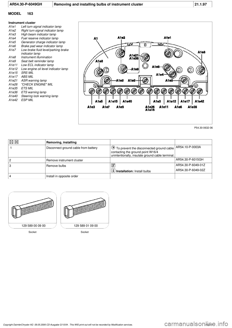
AR54.30-P-6049GH
Removing and installing bulbs of instrument cluster
21.1.97
MODEL
163
P54.30-0632-06
Instrument cluster
A1e1
Left turn signal indicator lamp
A1e2
Right turn signal indicator lamp
A1e3
High beam indicator lamp
A1e4
Fuel reserve indicator lamp
A1e5
Generator charge indicator lamp
A1e6
Brake pad wear indicator lamp
A1e7
Low brake fluid level/parking brake
indicator lamp
A1e8
Instrument illumination
A1e9
Seat belt reminder lamp
A1e11
Low ECL indicator lamp
A1e12
Low engine oil level indicator lamp
A1e15
SRS MIL
A1e17
ABS MIL
A1e21
ASR warning lamp
A1e26
"CHECK ENGINE" MIL
A1e35
ETS MIL
A1e36
ETS warning lamp
A1e40
Steering lock warning lamp
A1e42
ESP MIL
Removing, installing
1
Disconnect ground cable from battery
To prevent the disconnected ground cable
contacting the ground point W16/4
unintentionally, insulate ground cable terminal.
AR54.10-P-0003A
2
Remove instrument cluster
AR54.30-P-6015GH
3
Remove bulbs
AR54.30-P-6049-01Z
Installation:
Install bulbs
AR54.30-P-6049-02Z
4
Install in opposite order
129 589 00 09 00 129 589 01 09 00
Socket
Socket
Copyright DaimlerChrysler AG 09.05.2006 CD-Ausgabe G/10/04 . This WIS print-out will not be recorde
d by Modification services.
Page 1